EP2576108B1 - Ausdrehkopf auf einem balken - Google Patents
Ausdrehkopf auf einem balken Download PDFInfo
- Publication number
- EP2576108B1 EP2576108B1 EP11728363.0A EP11728363A EP2576108B1 EP 2576108 B1 EP2576108 B1 EP 2576108B1 EP 11728363 A EP11728363 A EP 11728363A EP 2576108 B1 EP2576108 B1 EP 2576108B1
- Authority
- EP
- European Patent Office
- Prior art keywords
- tool holder
- tool
- flange
- tool according
- conduit
- Prior art date
- Legal status (The legal status is an assumption and is not a legal conclusion. Google has not performed a legal analysis and makes no representation as to the accuracy of the status listed.)
- Active
Links
Images




Classifications
-
- B—PERFORMING OPERATIONS; TRANSPORTING
- B23—MACHINE TOOLS; METAL-WORKING NOT OTHERWISE PROVIDED FOR
- B23B—TURNING; BORING
- B23B29/00—Holders for non-rotary cutting tools; Boring bars or boring heads; Accessories for tool holders
- B23B29/03—Boring heads
- B23B29/034—Boring heads with tools moving radially, e.g. for making chamfers or undercuttings
-
- B—PERFORMING OPERATIONS; TRANSPORTING
- B23—MACHINE TOOLS; METAL-WORKING NOT OTHERWISE PROVIDED FOR
- B23B—TURNING; BORING
- B23B29/00—Holders for non-rotary cutting tools; Boring bars or boring heads; Accessories for tool holders
- B23B29/03—Boring heads
- B23B29/034—Boring heads with tools moving radially, e.g. for making chamfers or undercuttings
- B23B29/03403—Boring heads with tools moving radially, e.g. for making chamfers or undercuttings radially adjustable before starting manufacturing
- B23B29/03407—Boring heads with tools moving radially, e.g. for making chamfers or undercuttings radially adjustable before starting manufacturing by means of screws and nuts
- B23B29/0341—Cartridges
-
- B—PERFORMING OPERATIONS; TRANSPORTING
- B23—MACHINE TOOLS; METAL-WORKING NOT OTHERWISE PROVIDED FOR
- B23Q—DETAILS, COMPONENTS, OR ACCESSORIES FOR MACHINE TOOLS, e.g. ARRANGEMENTS FOR COPYING OR CONTROLLING; MACHINE TOOLS IN GENERAL CHARACTERISED BY THE CONSTRUCTION OF PARTICULAR DETAILS OR COMPONENTS; COMBINATIONS OR ASSOCIATIONS OF METAL-WORKING MACHINES, NOT DIRECTED TO A PARTICULAR RESULT
- B23Q1/00—Members which are comprised in the general build-up of a form of machine, particularly relatively large fixed members
- B23Q1/25—Movable or adjustable work or tool supports
- B23Q1/26—Movable or adjustable work or tool supports characterised by constructional features relating to the co-operation of relatively movable members; Means for preventing relative movement of such members
- B23Q1/28—Means for securing sliding members in any desired position
-
- B—PERFORMING OPERATIONS; TRANSPORTING
- B23—MACHINE TOOLS; METAL-WORKING NOT OTHERWISE PROVIDED FOR
- B23Q—DETAILS, COMPONENTS, OR ACCESSORIES FOR MACHINE TOOLS, e.g. ARRANGEMENTS FOR COPYING OR CONTROLLING; MACHINE TOOLS IN GENERAL CHARACTERISED BY THE CONSTRUCTION OF PARTICULAR DETAILS OR COMPONENTS; COMBINATIONS OR ASSOCIATIONS OF METAL-WORKING MACHINES, NOT DIRECTED TO A PARTICULAR RESULT
- B23Q1/00—Members which are comprised in the general build-up of a form of machine, particularly relatively large fixed members
- B23Q1/25—Movable or adjustable work or tool supports
- B23Q1/26—Movable or adjustable work or tool supports characterised by constructional features relating to the co-operation of relatively movable members; Means for preventing relative movement of such members
- B23Q1/28—Means for securing sliding members in any desired position
- B23Q1/282—Means for securing sliding members in any desired position co-operating with means to adjust the distance between the relatively slidable members
-
- B—PERFORMING OPERATIONS; TRANSPORTING
- B23—MACHINE TOOLS; METAL-WORKING NOT OTHERWISE PROVIDED FOR
- B23Q—DETAILS, COMPONENTS, OR ACCESSORIES FOR MACHINE TOOLS, e.g. ARRANGEMENTS FOR COPYING OR CONTROLLING; MACHINE TOOLS IN GENERAL CHARACTERISED BY THE CONSTRUCTION OF PARTICULAR DETAILS OR COMPONENTS; COMBINATIONS OR ASSOCIATIONS OF METAL-WORKING MACHINES, NOT DIRECTED TO A PARTICULAR RESULT
- B23Q11/00—Accessories fitted to machine tools for keeping tools or parts of the machine in good working condition or for cooling work; Safety devices specially combined with or arranged in, or specially adapted for use in connection with, machine tools
- B23Q11/10—Arrangements for cooling or lubricating tools or work
-
- B—PERFORMING OPERATIONS; TRANSPORTING
- B23—MACHINE TOOLS; METAL-WORKING NOT OTHERWISE PROVIDED FOR
- B23Q—DETAILS, COMPONENTS, OR ACCESSORIES FOR MACHINE TOOLS, e.g. ARRANGEMENTS FOR COPYING OR CONTROLLING; MACHINE TOOLS IN GENERAL CHARACTERISED BY THE CONSTRUCTION OF PARTICULAR DETAILS OR COMPONENTS; COMBINATIONS OR ASSOCIATIONS OF METAL-WORKING MACHINES, NOT DIRECTED TO A PARTICULAR RESULT
- B23Q11/00—Accessories fitted to machine tools for keeping tools or parts of the machine in good working condition or for cooling work; Safety devices specially combined with or arranged in, or specially adapted for use in connection with, machine tools
- B23Q11/10—Arrangements for cooling or lubricating tools or work
- B23Q11/1015—Arrangements for cooling or lubricating tools or work by supplying a cutting liquid through the spindle
- B23Q11/1023—Tool holders, or tools in general specially adapted for receiving the cutting liquid from the spindle
-
- B—PERFORMING OPERATIONS; TRANSPORTING
- B23—MACHINE TOOLS; METAL-WORKING NOT OTHERWISE PROVIDED FOR
- B23B—TURNING; BORING
- B23B2250/00—Compensating adverse effects during turning, boring or drilling
- B23B2250/04—Balancing rotating components
-
- B—PERFORMING OPERATIONS; TRANSPORTING
- B23—MACHINE TOOLS; METAL-WORKING NOT OTHERWISE PROVIDED FOR
- B23B—TURNING; BORING
- B23B2250/00—Compensating adverse effects during turning, boring or drilling
- B23B2250/12—Cooling and lubrication
-
- Y—GENERAL TAGGING OF NEW TECHNOLOGICAL DEVELOPMENTS; GENERAL TAGGING OF CROSS-SECTIONAL TECHNOLOGIES SPANNING OVER SEVERAL SECTIONS OF THE IPC; TECHNICAL SUBJECTS COVERED BY FORMER USPC CROSS-REFERENCE ART COLLECTIONS [XRACs] AND DIGESTS
- Y10—TECHNICAL SUBJECTS COVERED BY FORMER USPC
- Y10T—TECHNICAL SUBJECTS COVERED BY FORMER US CLASSIFICATION
- Y10T408/00—Cutting by use of rotating axially moving tool
- Y10T408/26—Cutting by use of rotating axially moving tool with means to condition tool
Definitions
- the present invention relates to the field of accessories for machine tools, numerically controlled, machining centers, flexible cells and workshops, and relates to a tool for boring on a sole plate for the production of accurate large-diameter holes in monolithic pieces of metal. large dimensions with very rigorous geometric characteristics, using interchangeable boring tools.
- the known boring heads of this type are generally equipped with two tools or a tool and a counterweight mounted diametrically opposite on a drive soleplate, with possibility of adjustment in position on the latter by sliding in a corresponding slide, then clamping in this slide by pinching.
- Precision during adjustment is therefore very important for this type of tool holder and it is also essential to avoid any dispersion during final blocking.
- it is necessary to maintain the tool holder (s) on the sole to take account of the continuous increase in rotation speeds, in relation to the evolution of technological progress, which causes a corresponding increase in centrifugal forces exerted on the tool holders and, as a corollary, a corresponding risk of separation between the sole and the tool holder (s), for example due to insufficient tightening.
- the cutting inserts used on the tools equipping these tool holders are generally lubricated by means of lubrication devices, commonly called lubrication towers, which are arranged at a distance from the cutting zone.
- lubrication towers which are arranged at a distance from the cutting zone.
- the present invention aims to overcome these disadvantages by proposing a boring tool on the sole according to claim 1, and allowing a prior connection between the sole and the or tool holders and / or a counterweight, while allowing the adjustment of position of the tool holder or counterweight before final tightening on the sole, and effective lubrication of the cutting edge or edges.
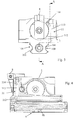
- the assembly 5 for guiding and blocking the slide 4 for guiding and holding for at least one tool holder 1 and a counterweight 2000 is constituted by a fixed peg 5 'clamped in a corresponding longitudinal housing of a side wall of the slide 4 and a movable pin 5 "mounted, movably by means of screws 51, in a housing opposite to that of receiving the fixed pin 5 '( figures 1 , 2 and 6 ).
- the tightening of the screws 51 moves the movable pin 5 "towards the fixed pin 5.
- the toolholder 1 is provided with guide means 100 intended to cooperate with the fixed rods 5. and movable 5 ", for the displacement of said tool holder 1 in the sole 2 and for its locking in position.
- the movable pin 5 By tightening the screws 51, the movable pin 5 "presses on the corresponding guide means 100 of the tool holder 1 and thus blocks the latter in the slide 4 by clamping in cooperation with the fixed peg 5 '. made a guide and a link in translation similar to those of a dovetail guide device, the radial retention resistant to the centrifugal force being obtained by pinching the means 100 of said tool holder 1 in the slide 4 comprising the pins 5 'and 5 "of the sole 2.
- the mounting of the mobile rod 5" is of known type and consists simply by fixing said rod inside the slide 4 by means of screws embedded in said rod 5 ", which is mounted on said screws against the action of springs tending to apply against the corresponding inner wall of the slide 4.
- the positioning pin 6 of a tool holder 1 or a counterweight 2000 is housed in the bottom of the slide 4 of the sole 2 and is operable via a rotary shaft 60 provided with a cam 61 for moving this lug 6 ( figure 5 ).
- This lug 6 is intended to cooperate with a device 9 for precise adjustment of the tool holder 1, housed in the bottom of this tool holder 1 at the corresponding guide means 100 of the tool holder 1 and in particular with a nut 91 of the last.
- the means 7 for centralized lubrication of the cutting edge (s) 8 of the tool holder (s) 1 housed in the soleplate 2 consists of a central bore 71 for the arrival of lubricant connected to tangential conduits 72 extending into the sole 2, parallel to its longitudinal edges and opening into perpendicular ducts 73 ( figures 1 and 6 ).
- the tool holder 1 is provided with gripping means 101 intended to cooperate with the assembly 5 for guiding and locking the slide 4 for guiding and holding the fastening flange 2, which is additionally provided with a device 10 for limiting the travel of the tool carrier 1 or the counterweight 2000 ( Figures 1 to 3 ).
- the lug 6 for positioning a tool holder 1 or a counterweight 2000 is eclipsable when setting up a tool holder 1 or a counterweight 2000 and automatically returns to position after this implementation and each tool holder 1 is provided with a device 11 for lubricating the edge 8 of the tool, connected to the means 7 for centralized lubrication of the sole 2 ( figure 5 ).
- the gripping means 101 of the tool holder advantageously consist of striations or the like projecting from the general shape of the guide means 100 provided on the tool holder 1 ( Figures 1 to 3 ).
- the material constituting the guide means 100 of the tool holder 1, and therefore the striations forming the gripping means 101 is a material having a hardness greater than that of the constituent material of the fixed 5 'and mobile 5 "pegs forming the assembly 5 for guiding and blocking the slideway 4.
- the contact surface between the guide means 100 and the assembly 5 is reduced and reduced to a multitude of linear contacts, so that because of the higher hardness of the gripping means 101, the striations forming these Means perform a corresponding elastic deformation of the surface of the peg 5 'and 5 "allowing a gripping significantly improving the sliding resistance compared to a smooth contact.
- this slip resistance can be improved by nearly 50%
- the locking of the tool holder 1 in the sole 2 is very much improved, which contributes to an improved maintenance of the tool holder 1, as well as the counterweight 2000, in the sole 2 and therefore to a higher resistance. high centrifugal forces generated by the very high speeds of rotation.
- the device 10 for limiting the stroke of the tool carrier 1 or the counterweight 2000 ( figures 1 , 2 and 6 ) consists, on the one hand, in a lateral groove 10 'provided on a lateral shoulder of the tool holder 1 resting on an edge of the sole 2 delimiting the slide 4 and, on the other hand, in a washer 10 " or a plate fixed in a housing on the corresponding side of the sole 2 and having a portion protruding from the corresponding bearing edge of the tool holder 1, this projecting portion cooperating with the lateral groove 10 '.
- the washer 10 "or plate is fixed on the sole 2 by means of a screw 10"'.
- the washer 10 "or plate is mounted on a stepped screw 10" having two reverse or differential pitch threads and is held against rotation by means of a pin 1000.
- the screw 10 "' is advantageously at its end on the mobile rod 5 ".
- the washer 10 is mounted on the inverted thread or the differential pitch thread of the screw 10"' with prediction of an initial offset between the bottom corresponding housing of the sole 2 and the corresponding wall of the washer 10 "or the wafer so that the screwing of the screw 10" 'in the sole 2 takes place with holding the washer 10 "or the wafer by the pin 1000 to avoid its rotation.
- the lug 6 for positioning a tool holder 1 or a counterweight 2000 is mounted in the bottom of the slide 4 of the sole 2 with the possibility of displacement against the action of a return spring 62 acting on the cam 61 of displacement of this lug 6.
- the lug 6 remains continuously protruding on the bottom of the slide 4 to cooperate with the nut 91 of the device 9 for precise adjustment of the tool holder 1 ( figure 5 ).
- the device 9 for precise adjustment of the tool holder 1 is advantageously provided, for its snapping, a biased surface promoting the eclipsing of the lug 6 to snap it.
- the device 9 for precise adjustment of the tool holder 1, housed in the bottom of this tool holder 1 at the corresponding guide means 100 of the tool holder 1, is of a type known per se and does not require any particular description, not in itself the object of the present invention.
- the device 11 for lubricating the cutting edge 8 of the tool, connected to the means 7 for centralized lubrication of the sole 2 essentially consists, on the one hand, of a connecting device 111 connected, on the one hand, to a perpendicular duct 73 of the means 7 for centralized lubrication of the sole 2 ( figure 1 ) and, secondly, to a longitudinal duct 112 provided in the body of the tool holder 101 and extended vertically, on the opposite side to the connecting device 111 by a vertical duct 113 opening into a nozzle 114 of watering the cutting edge 8.
- connection device 111 advantageously consists of a first duct 111 'communicating with or inserted in the duct 73 of the centralized lubrication means 7 with the interposition of an O-ring or the like, this duct 111' opening into a body 111 "extended by a second conduit 111 “'penetrating into the longitudinal conduit 112 provided in the body of the tool holder 101, the seal at the latter connection being also performed by an O-ring or the like.
- the nozzle 114 for watering the cutting edge 8 is a flat jet nozzle.
- This nozzle may advantageously be in the form of a hollow screw provided with an elongate end slot, this hollow screw being glued after position adjustment in a corresponding housing provided at the end of the vertical conduit 113 of the tool holder 1 .
- the invention it is possible to produce a boring tool, particularly for producing large diameters in large monolithic parts, allowing a perfect and reliable positioning of the tool, as well as a very precise adjustment of the unbalance .
- a holding and positioning of the tool holder 1 on the sole 2 can be obtained immediately during the establishment of the tool holder, before adjustment, so that immediate security against accidental mishandling is ensured. .
- the final blocking is improved and additional security is ensured by the implementation of the vertical duct 113 of the stroke limiting device of the tool holder 1.
Landscapes
- Engineering & Computer Science (AREA)
- Mechanical Engineering (AREA)
- Cutting Tools, Boring Holders, And Turrets (AREA)
- Auxiliary Devices For Machine Tools (AREA)
- Gripping On Spindles (AREA)
- Jigs For Machine Tools (AREA)
Claims (13)
- Ausdrehwerkzeug auf einem Balken, bestehend aus mindestens einem Werkzeughalter (1) und einem Balken (2) zur Befestigung auf einer Maschinenspindel (3), versehen einerseits mit einer Gleitschiene (4) zum Führen und Halten des genannten mindestens einen Werkzeughalters (1) senkrecht zur Achse der genannten Spindel (3) mit Hilfe einer Führungs- und Blockiereinheit (5), und andererseits mit mindestens einem Zapfen (6) zur Positionierung des Werkzeughalters (1) oder eines Gegengewichts (2000), wobei der Werkzeughalter (1) mit Haltemitteln (101) versehen ist, die dazu bestimmt sind, mit der Führungs- und Blockiereinheit (5) der Gleitschiene (4) zum Führen und Halten des Befestigungsbalkens (2) zusammenzuwirken, der außerdem mit einer Endanschlagsvorrichtung (10) für den Werkzeughalter (1) oder das Gegengewicht (2000) versehen ist,
dadurch gekennzeichnet, dass der Balken (2) außerdem ein Mittel (7) zur zentralisierten Schmierung der Schneide(n) (8) des oder der Werkzeughalter/s (1), der/die auf dem genannten Balken (2) montiert sind, aufweist, dadurch, dass der Positionierungszapfen (6) des Werkzeughalters (1) oder des Gegengewichts (2000) dafür eingerichtet ist, bei seiner Positionierung unter der Wirkung einer Einstellvorrichtung des Werkzeughalters (1) oder des Gegengewichts (2000) verschoben zu werden und nach dieser Positionierung automatisch wieder in seine Stellung zurückkehrt, und dadurch, dass
jeder Werkzeughalter (1) mit einer Vorrichtung (11) zur Schmierung der Schneide des Werkzeugs versehen ist, die mit dem Mittel zur zentralisierten Schmierung (7) des Balkens (2) verbunden ist. - Ausdrehwerkzeug nach Patentanspruch 1, dadurch gekennzeichnet, dass die Haltemittel (101) des Werkzeughalters in Rippen oder Ähnlichem bestehen, die aus der allgemeinen Form der Führungsmittel (100), die am Werkzeughalter (1) vorgesehen sind, herausragen.
- Ausdrehwerkzeug nach Patentanspruch 2, dadurch gekennzeichnet, dass der Werkstoff, aus dem die Führungsmittel (100) des Werkzeughalters (1) und die Rippen, die die Haltemittel (101) bilden, bestehen, ein Werkstoff ist, der eine größere Härte aufweist, als der Werkstoff, aus dem die festen (5') und beweglichen Stäbe (5") bestehen, die das Führungs- und Blockiermittel (5) der Gleitschiene (4) bilden.
- Ausdrehwerkzeug nach Patentanspruch 1, dadurch gekennzeichnet, dass die Endanschlagsvorrichtung (10) für den Werkzeughalter (1) oder das Gegengewicht (2000) aus einerseits einer seitlichen Rille (10'), die in einer seitlichen Schulter des Werkzeughalters (1), die an einem Rand des Balkens (2) anliegt, der die Gleitschiene (4) begrenzt, besteht und andererseits einer in einer Aufnahme der entsprechenden Seite des Balkens (2) befestigten und ein gegenüber dem entsprechenden Anlagerand des Werkzeughalters (1) hervorstehendes Teil aufweisenden Scheibe (10") oder Plättchen, wobei dieser hervorstehende Teil mit der seitlichen Rille (10') zusammenwirkt.
- Ausdrehwerkzeug nach Patentanspruch 4, dadurch gekennzeichnet, dass die Scheibe (10") oder das Plättchen über eine Schraube (10"') am Balken (2) befestigt wird.
- Ausdrehwerkzeug nach einem der Patentansprüche 4 oder 5, dadurch gekennzeichnet, dass die Scheibe (10") oder das Plättchen auf einer abgesetzten Schraube (10"') montiert ist, die zwei gegenläufige Gewinde oder Gewinde mit unterschiedlicher Ganghöhe aufweist und mit Hilfe eines Stiftes (1000) drehfest gehalten wird.
- Ausdrehwerkzeug nach Patentanspruch 3 in Kombination mit einem der Patentansprüche 5 oder 6, dadurch gekennzeichnet, dass die Schraube (10"') mit ihrem Ende auf den beweglichen Stab (5") einwirkt.
- Ausdrehwerkzeug nach einem der Patentansprüche 4 oder 5 in Kombination mit Patentanspruch 6, dadurch gekennzeichnet, dass die Scheibe (10") auf dem gegenläufigen Gewinde oder Gewinde mit unterschiedlicher Ganghöhe der Schraube (10"') montiert ist, wobei ein anfänglicher Versatz zwischen dem Boden der entsprechenden Aufnahme des Balkens (2) und der entsprechenden Seite der Scheibe (10") oder des Plättchens vorgesehen wird, derart, dass das Schrauben der Schraube (10"') im Balken (2) unter Festhalten der Scheibe (10") oder des Plättchens durch den Stift (1000) zur Vermeidung ihrer Drehung erfolgt.
- Ausdrehwerkzeug nach Patentanspruch 1, dadurch gekennzeichnet, dass der Positionierungszapfen (6) eines Werkzeughalters (1) oder eines Gegengewichts (2000) am Boden der Gleitschiene (4) des Schlittens (2) mit der Möglichkeit zur Verschiebung gegen die Wirkung einer Rückstellfeder (62) montiert ist, die auf den Nocken (61) zur Verschiebung dieses Zapfens (6) einwirkt.
- Ausdrehwerkzeug nach Patentanspruch 1, dadurch gekennzeichnet, dass die Vorrichtung (11) zur Schmierung der Schneide (8) des Werkzeugs, die mit dem Mittel zur zentralisierten Schmierung (7) des Balkens (2) verbunden ist, im Wesentlichen aus einer Anschlussvorrichtung (111) besteht, die einerseits mit einer senkrechten Leitung (73) des Mittels zur zentralisierten Schmierung (7) des Balkens (2) verbunden ist und andererseits mit einer in Längsrichtung verlaufenden Leitung (112), die im Körper des Werkzeughalters (101) vorgesehen ist und sich vertikal auf der der Anschlussvorrichtuing (111) entgegengesetzten Seite in einer vertikalen Leitung (113) fortsetzt, die in einer Düse (114) zur Begiessung der Schneide (8) mündet.
- Ausdrehwerkzeug nach Patentanspruch 10, dadurch gekennzeichnet, dass die Anschlussvorrichtung (111) aus einer ersten Leitung (111') besteht, die mit der Leitung (73) des Mittels zur zentralisierten Schmierung (7) unter Einfügung einer O-Ringdichtung oder dergleichen in Verbindung steht oder in sie eingesetzt ist, wobei diese Leitung (111') in einen Körper (111") mündet, der sich in einer zweiten Leitung (111"') fortsetzt, die in die Leitung in Längsrichtung (112) einmündet, die im Körper des Werkzeughalters (101) vorgesehen ist, wobei die Dichtigkeit dieser letzten Verbindung ebenfalls durch eine O-Ringdichtung oder dergleichen sichergestellt wird.
- Ausdrehwerkzeug nach Patentanspruch 10, dadurch gekennzeichnet, dass die Düse (114) zur Schmierung der Schneide (8) eine Flachstrahldüse ist.
- Ausdrehwerkzeug nach Patentanspruch 12, dadurch gekennzeichnet, dass die Düse (114) in Form einer hohlen Schraube ausgebildet ist, die an ihrem Ende mit einem länglichen Schlitz versehen ist, wobei diese hohle Schraube nach Justieren der Stellung in eine entsprechende Aufnahme geklebt wird, die am Ende der vertikalen Leitung (113) des Werkzeughalters (1) vorgesehen ist.
Applications Claiming Priority (2)
| Application Number | Priority Date | Filing Date | Title |
|---|---|---|---|
| FR1054461A FR2960805B1 (fr) | 2010-06-07 | 2010-06-07 | Outil a aleser sur semelle |
| PCT/FR2011/051280 WO2011154649A1 (fr) | 2010-06-07 | 2011-06-07 | Outil a aléser sur semelle |
Publications (2)
| Publication Number | Publication Date |
|---|---|
| EP2576108A1 EP2576108A1 (de) | 2013-04-10 |
| EP2576108B1 true EP2576108B1 (de) | 2016-09-28 |
Family
ID=43407814
Family Applications (1)
| Application Number | Title | Priority Date | Filing Date |
|---|---|---|---|
| EP11728363.0A Active EP2576108B1 (de) | 2010-06-07 | 2011-06-07 | Ausdrehkopf auf einem balken |
Country Status (7)
| Country | Link |
|---|---|
| US (1) | US9283624B2 (de) |
| EP (1) | EP2576108B1 (de) |
| KR (1) | KR101795106B1 (de) |
| CN (1) | CN102985202B (de) |
| FR (1) | FR2960805B1 (de) |
| TW (1) | TWI558496B (de) |
| WO (1) | WO2011154649A1 (de) |
Families Citing this family (16)
| Publication number | Priority date | Publication date | Assignee | Title |
|---|---|---|---|---|
| NO333697B1 (no) | 2011-03-11 | 2013-08-26 | Teeness Asa | Anordning for innvendig sponskjaerende bearbeiding med en dyse for spyling av skjaervaeske mot skjaeret |
| CN103586711A (zh) * | 2013-10-25 | 2014-02-19 | 安徽机电职业技术学院 | 一种电机座镗孔专用夹具 |
| US9486862B1 (en) * | 2014-07-25 | 2016-11-08 | Anthony P. LaMarca, Sr. | Fly cutter cutting tool |
| KR101693839B1 (ko) * | 2015-01-05 | 2017-01-06 | 두산중공업 주식회사 | 강(steel)으로 이루어진 보강대를 포함하여 열변형 방지 기능이 개선된 보링 헤드 |
| EP3050654B1 (de) * | 2015-01-30 | 2022-03-23 | Sandvik Intellectual Property AB | Werkzeug mit dummy-chip |
| EP3222375B1 (de) * | 2016-03-24 | 2021-08-18 | Sandvik Intellectual Property AB | Bohrwerkzeug |
| CN109440054B (zh) * | 2018-12-25 | 2024-01-30 | 中国人民解放军陆军装甲兵学院 | 一种用于旋转式内孔等离子喷涂的柔性快装转接体 |
| US10940551B1 (en) | 2019-08-30 | 2021-03-09 | Kennametal Inc. | Lightweight cutting tool |
| US11504784B2 (en) | 2020-12-09 | 2022-11-22 | Kennametal Inc. | Cutting tool with interconnected arms for increased stiffness to weight ratio |
| US11571759B2 (en) | 2020-12-09 | 2023-02-07 | Kennametal Inc. | Cutting tool with directed fluid flow to facilitate chip evacuation |
| CN112974903B (zh) * | 2021-02-25 | 2022-07-08 | 中山市朝逸金属制品有限公司 | 一种金属五金制品钻孔用数控机床 |
| US11883894B2 (en) | 2021-07-13 | 2024-01-30 | Kennametal Inc. | Composite cutting tool |
| DE202022000109U1 (de) * | 2022-01-06 | 2023-04-17 | Nsh Technology Gmbh | Drehwerkzeug zur spanenden Bearbeitung von unrunden Profilen |
| US11911835B2 (en) | 2022-03-23 | 2024-02-27 | Kennametal Inc. | Lightweight rotary cutting tool |
| CN117754010B (zh) * | 2024-02-21 | 2024-06-04 | 江苏久保联实业有限公司 | 一种炉管用镗削直径可变的镗刀装置 |
| CN118180446B (zh) * | 2024-05-17 | 2024-07-16 | 山西衡杉钻具有限公司 | 一种无磁钻铤镗孔装置 |
Family Cites Families (24)
| Publication number | Priority date | Publication date | Assignee | Title |
|---|---|---|---|---|
| US1251140A (en) * | 1917-06-18 | 1917-12-25 | Expandem Tool And Mfg Company | Boring-tool. |
| US1251139A (en) * | 1917-06-18 | 1917-12-25 | Expandem Tool And Mfg Company | Boring-tool. |
| BE333778A (de) * | 1925-06-02 | |||
| US1824543A (en) * | 1926-12-28 | 1931-09-22 | Floyd S Hartwell | Boring bar |
| DE1103112B (de) * | 1957-08-02 | 1961-03-23 | Neher Maschf A | Anstellschraube fuer Bohrstangeneinsaetze |
| US3067637A (en) * | 1960-05-27 | 1962-12-11 | Bernard A Horning | Undercutting tool |
| US3207015A (en) * | 1963-11-04 | 1965-09-21 | Gen Motors Corp | Cutting tool adjustment assembly |
| CH540734A (de) * | 1970-11-27 | 1973-08-31 | Gildemeister Devlieg System | Bohrwerkzeug mit zwei verstellbaren Schneidplattenhaltern |
| DE2236828C2 (de) * | 1972-07-27 | 1974-08-01 | Emil Wohlhaupter & Co, 7443 Frickenhausen | Bohr- oder Ausdrehkopf |
| US4040315A (en) * | 1976-05-24 | 1977-08-09 | The Valeron Corporation | Machining cross-feed head counterweight system |
| CH656334A5 (de) * | 1982-06-28 | 1986-06-30 | Kaiser Heinz Ag | Ausdrehwerkzeug. |
| FR2563132B1 (fr) * | 1984-04-24 | 1988-05-06 | Pfalzgraf Emile | Tete d'alesage |
| FR2570008B2 (fr) * | 1984-04-24 | 1988-08-05 | Pfalzgraf Emile | Tete d'alesage |
| FR2645055A1 (fr) * | 1989-03-31 | 1990-10-05 | Gamet Precision | Appareil a aleser et surfacer, a avance et recul automatiques |
| CH691435A5 (de) * | 1996-05-02 | 2001-07-31 | Kaiser Heinz Ag | Ausdrehkopf. |
| FR2813812B1 (fr) * | 2000-09-11 | 2002-11-29 | Epb | Tete a aleser |
| DE10216538C2 (de) * | 2001-06-22 | 2003-11-27 | Koyemann Werkzeuge Gmbh & Co O | Werkzeugkopf |
| JP2005523171A (ja) * | 2002-04-25 | 2005-08-04 | カーデモン・インコーポレーテッド,ディー/ビー/エイ カー−テック・カンパニー | 細密調整付きの摺動可能な穿孔工具 |
| FI117593B (fi) * | 2002-06-28 | 2006-12-15 | Mandrel Oy | Järjestely lastuavaan työstöön |
| ITMI20061909A1 (it) * | 2006-10-04 | 2008-04-05 | D Andrea Spa | Utensile per forare e alesare munito di taglienti registrabili |
| CN101301687B (zh) * | 2008-06-13 | 2011-07-20 | 十堰高明精密机械有限公司 | 精密数控镗头 |
| TWM360098U (en) * | 2009-02-25 | 2009-07-01 | Shi-Xiong Cai | Improved seat structure for cutter boring large aperture |
| DE102009051843A1 (de) * | 2009-10-29 | 2011-05-05 | Wohlhaupter Gmbh | Feindrehwerkzeug |
| JP5703639B2 (ja) * | 2010-09-06 | 2015-04-22 | 株式会社ジェイテクト | 工具径調整装置を備える工作機械 |
-
2010
- 2010-06-07 FR FR1054461A patent/FR2960805B1/fr active Active
-
2011
- 2011-06-07 TW TW100119780A patent/TWI558496B/zh not_active IP Right Cessation
- 2011-06-07 CN CN201180033609.3A patent/CN102985202B/zh active Active
- 2011-06-07 US US13/701,974 patent/US9283624B2/en active Active
- 2011-06-07 WO PCT/FR2011/051280 patent/WO2011154649A1/fr not_active Ceased
- 2011-06-07 KR KR1020137000281A patent/KR101795106B1/ko active Active
- 2011-06-07 EP EP11728363.0A patent/EP2576108B1/de active Active
Also Published As
| Publication number | Publication date |
|---|---|
| FR2960805B1 (fr) | 2013-04-26 |
| FR2960805A1 (fr) | 2011-12-09 |
| WO2011154649A1 (fr) | 2011-12-15 |
| TW201206620A (en) | 2012-02-16 |
| CN102985202A (zh) | 2013-03-20 |
| US20130294855A1 (en) | 2013-11-07 |
| TWI558496B (zh) | 2016-11-21 |
| KR101795106B1 (ko) | 2017-11-07 |
| KR20130052596A (ko) | 2013-05-22 |
| US9283624B2 (en) | 2016-03-15 |
| EP2576108A1 (de) | 2013-04-10 |
| CN102985202B (zh) | 2015-05-20 |
Similar Documents
| Publication | Publication Date | Title |
|---|---|---|
| FR2960805A1 (fr) | Outil a aleser sur semelle | |
| EP2168703B1 (de) | Werkzeugträger mit Axialverstellung | |
| EP0340369B1 (de) | Vorrichtung zur Befestigung von Werkzeughaltern und Werkzeugen mit konischen und planen Tragflächen, insbesondere für Bearbeitungszentren mit automatischen oder manuellen Werkzeugwechslern | |
| EP0317682A1 (de) | Zusammenbauvorrichtung für einen Kegelschaft, insbesondere für 7/24 Kegelschäfte, verwendet für Anbauvorrichtungen, Werkzeughalter und Werkzeuge | |
| EP0163796A1 (de) | Bohrkopf | |
| FR2635031A1 (fr) | Pince adaptable a une machine-outil comportant un mandrin de prehension | |
| EP0373086A1 (de) | Montagevorrichtung für Kegelschäfte, insbesondere mit 7/24-Kegel für Anordnungen, Werkzeughalter und Werkzeuge | |
| CA2410521C (fr) | Tete a aleser | |
| EP0841114B1 (de) | Spannvorrichtung für Werkzeughalter mit Hohlkonus | |
| WO2006027446A1 (fr) | Tete a aleser | |
| FR2468438A1 (fr) | Dispositif porte-outil pour machines-outils | |
| EP1796871A1 (de) | Vorrichtung zum einspannen eines werkzeugeinsatzes in eine schleifmaschine | |
| EP2648877B1 (de) | Klemm-/löseflansch | |
| FR2567432A1 (fr) | Porte-outil, en particulier pour un outil tournant, muni d'un dispositif de reglage axial | |
| CH688794A5 (fr) | Outil de coupe à plaquettes amovibles. | |
| WO2000029152A1 (fr) | Dispositif de perçage de trous fil freins | |
| EP0949030A1 (de) | Drehendes Schneidwerkzeug | |
| EP0234171A1 (de) | Ausdrehkopf | |
| EP0230200A1 (de) | Axiale Regelungsvorrichtung von Werkzeugen in Werkzeugmaschinen | |
| EP3572173B1 (de) | Führungsbuchse eines schneidewerkzeugs, entsprechende bohrmaschine und entsprechendes bohrsystem, verwendung des bohrsystems und wartungsverfahren der bohrmaschine | |
| FR2563132A1 (fr) | Tete d'alesage | |
| EP0113304B2 (de) | Gewindebohrfutter | |
| EP0210128B1 (de) | Kupplungsvorrichtung zwischen einer Barbeitungsmaschinenspindel und einem Werkzeughalter | |
| FR2638991A1 (fr) | Dispositif de montage a queue conique, en particulier au cone 7/24, a application cone et face pour attachements, porte-outils et outils | |
| EP0314544A1 (de) | Spannfutter, insbesondere für Maschinen mit automatischem Vorschub |
Legal Events
| Date | Code | Title | Description |
|---|---|---|---|
| PUAI | Public reference made under article 153(3) epc to a published international application that has entered the european phase |
Free format text: ORIGINAL CODE: 0009012 |
|
| 17P | Request for examination filed |
Effective date: 20130104 |
|
| AK | Designated contracting states |
Kind code of ref document: A1 Designated state(s): AL AT BE BG CH CY CZ DE DK EE ES FI FR GB GR HR HU IE IS IT LI LT LU LV MC MK MT NL NO PL PT RO RS SE SI SK SM TR |
|
| DAX | Request for extension of the european patent (deleted) | ||
| GRAP | Despatch of communication of intention to grant a patent |
Free format text: ORIGINAL CODE: EPIDOSNIGR1 |
|
| INTG | Intention to grant announced |
Effective date: 20160421 |
|
| GRAS | Grant fee paid |
Free format text: ORIGINAL CODE: EPIDOSNIGR3 |
|
| GRAA | (expected) grant |
Free format text: ORIGINAL CODE: 0009210 |
|
| AK | Designated contracting states |
Kind code of ref document: B1 Designated state(s): AL AT BE BG CH CY CZ DE DK EE ES FI FR GB GR HR HU IE IS IT LI LT LU LV MC MK MT NL NO PL PT RO RS SE SI SK SM TR |
|
| REG | Reference to a national code |
Ref country code: GB Ref legal event code: FG4D Free format text: NOT ENGLISH |
|
| REG | Reference to a national code |
Ref country code: CH Ref legal event code: EP |
|
| REG | Reference to a national code |
Ref country code: AT Ref legal event code: REF Ref document number: 832313 Country of ref document: AT Kind code of ref document: T Effective date: 20161015 |
|
| REG | Reference to a national code |
Ref country code: IE Ref legal event code: FG4D Free format text: LANGUAGE OF EP DOCUMENT: FRENCH |
|
| REG | Reference to a national code |
Ref country code: DE Ref legal event code: R096 Ref document number: 602011030750 Country of ref document: DE |
|
| REG | Reference to a national code |
Ref country code: LT Ref legal event code: MG4D |
|
| PG25 | Lapsed in a contracting state [announced via postgrant information from national office to epo] |
Ref country code: HR Free format text: LAPSE BECAUSE OF FAILURE TO SUBMIT A TRANSLATION OF THE DESCRIPTION OR TO PAY THE FEE WITHIN THE PRESCRIBED TIME-LIMIT Effective date: 20160928 Ref country code: NO Free format text: LAPSE BECAUSE OF FAILURE TO SUBMIT A TRANSLATION OF THE DESCRIPTION OR TO PAY THE FEE WITHIN THE PRESCRIBED TIME-LIMIT Effective date: 20161228 Ref country code: LT Free format text: LAPSE BECAUSE OF FAILURE TO SUBMIT A TRANSLATION OF THE DESCRIPTION OR TO PAY THE FEE WITHIN THE PRESCRIBED TIME-LIMIT Effective date: 20160928 Ref country code: FI Free format text: LAPSE BECAUSE OF FAILURE TO SUBMIT A TRANSLATION OF THE DESCRIPTION OR TO PAY THE FEE WITHIN THE PRESCRIBED TIME-LIMIT Effective date: 20160928 Ref country code: RS Free format text: LAPSE BECAUSE OF FAILURE TO SUBMIT A TRANSLATION OF THE DESCRIPTION OR TO PAY THE FEE WITHIN THE PRESCRIBED TIME-LIMIT Effective date: 20160928 |
|
| REG | Reference to a national code |
Ref country code: NL Ref legal event code: MP Effective date: 20160928 |
|
| REG | Reference to a national code |
Ref country code: AT Ref legal event code: MK05 Ref document number: 832313 Country of ref document: AT Kind code of ref document: T Effective date: 20160928 |
|
| PG25 | Lapsed in a contracting state [announced via postgrant information from national office to epo] |
Ref country code: GR Free format text: LAPSE BECAUSE OF FAILURE TO SUBMIT A TRANSLATION OF THE DESCRIPTION OR TO PAY THE FEE WITHIN THE PRESCRIBED TIME-LIMIT Effective date: 20161229 Ref country code: SE Free format text: LAPSE BECAUSE OF FAILURE TO SUBMIT A TRANSLATION OF THE DESCRIPTION OR TO PAY THE FEE WITHIN THE PRESCRIBED TIME-LIMIT Effective date: 20160928 Ref country code: LV Free format text: LAPSE BECAUSE OF FAILURE TO SUBMIT A TRANSLATION OF THE DESCRIPTION OR TO PAY THE FEE WITHIN THE PRESCRIBED TIME-LIMIT Effective date: 20160928 Ref country code: NL Free format text: LAPSE BECAUSE OF FAILURE TO SUBMIT A TRANSLATION OF THE DESCRIPTION OR TO PAY THE FEE WITHIN THE PRESCRIBED TIME-LIMIT Effective date: 20160928 |
|
| PG25 | Lapsed in a contracting state [announced via postgrant information from national office to epo] |
Ref country code: EE Free format text: LAPSE BECAUSE OF FAILURE TO SUBMIT A TRANSLATION OF THE DESCRIPTION OR TO PAY THE FEE WITHIN THE PRESCRIBED TIME-LIMIT Effective date: 20160928 Ref country code: RO Free format text: LAPSE BECAUSE OF FAILURE TO SUBMIT A TRANSLATION OF THE DESCRIPTION OR TO PAY THE FEE WITHIN THE PRESCRIBED TIME-LIMIT Effective date: 20160928 |
|
| REG | Reference to a national code |
Ref country code: FR Ref legal event code: PLFP Year of fee payment: 7 |
|
| PG25 | Lapsed in a contracting state [announced via postgrant information from national office to epo] |
Ref country code: BG Free format text: LAPSE BECAUSE OF FAILURE TO SUBMIT A TRANSLATION OF THE DESCRIPTION OR TO PAY THE FEE WITHIN THE PRESCRIBED TIME-LIMIT Effective date: 20161228 Ref country code: SK Free format text: LAPSE BECAUSE OF FAILURE TO SUBMIT A TRANSLATION OF THE DESCRIPTION OR TO PAY THE FEE WITHIN THE PRESCRIBED TIME-LIMIT Effective date: 20160928 Ref country code: SM Free format text: LAPSE BECAUSE OF FAILURE TO SUBMIT A TRANSLATION OF THE DESCRIPTION OR TO PAY THE FEE WITHIN THE PRESCRIBED TIME-LIMIT Effective date: 20160928 Ref country code: AT Free format text: LAPSE BECAUSE OF FAILURE TO SUBMIT A TRANSLATION OF THE DESCRIPTION OR TO PAY THE FEE WITHIN THE PRESCRIBED TIME-LIMIT Effective date: 20160928 Ref country code: IS Free format text: LAPSE BECAUSE OF FAILURE TO SUBMIT A TRANSLATION OF THE DESCRIPTION OR TO PAY THE FEE WITHIN THE PRESCRIBED TIME-LIMIT Effective date: 20170128 Ref country code: CZ Free format text: LAPSE BECAUSE OF FAILURE TO SUBMIT A TRANSLATION OF THE DESCRIPTION OR TO PAY THE FEE WITHIN THE PRESCRIBED TIME-LIMIT Effective date: 20160928 Ref country code: ES Free format text: LAPSE BECAUSE OF FAILURE TO SUBMIT A TRANSLATION OF THE DESCRIPTION OR TO PAY THE FEE WITHIN THE PRESCRIBED TIME-LIMIT Effective date: 20160928 Ref country code: PT Free format text: LAPSE BECAUSE OF FAILURE TO SUBMIT A TRANSLATION OF THE DESCRIPTION OR TO PAY THE FEE WITHIN THE PRESCRIBED TIME-LIMIT Effective date: 20170130 Ref country code: PL Free format text: LAPSE BECAUSE OF FAILURE TO SUBMIT A TRANSLATION OF THE DESCRIPTION OR TO PAY THE FEE WITHIN THE PRESCRIBED TIME-LIMIT Effective date: 20160928 |
|
| REG | Reference to a national code |
Ref country code: DE Ref legal event code: R097 Ref document number: 602011030750 Country of ref document: DE |
|
| PG25 | Lapsed in a contracting state [announced via postgrant information from national office to epo] |
Ref country code: DK Free format text: LAPSE BECAUSE OF FAILURE TO SUBMIT A TRANSLATION OF THE DESCRIPTION OR TO PAY THE FEE WITHIN THE PRESCRIBED TIME-LIMIT Effective date: 20160928 |
|
| PLBE | No opposition filed within time limit |
Free format text: ORIGINAL CODE: 0009261 |
|
| STAA | Information on the status of an ep patent application or granted ep patent |
Free format text: STATUS: NO OPPOSITION FILED WITHIN TIME LIMIT |
|
| 26N | No opposition filed |
Effective date: 20170629 |
|
| PG25 | Lapsed in a contracting state [announced via postgrant information from national office to epo] |
Ref country code: SI Free format text: LAPSE BECAUSE OF FAILURE TO SUBMIT A TRANSLATION OF THE DESCRIPTION OR TO PAY THE FEE WITHIN THE PRESCRIBED TIME-LIMIT Effective date: 20160928 |
|
| PG25 | Lapsed in a contracting state [announced via postgrant information from national office to epo] |
Ref country code: MC Free format text: LAPSE BECAUSE OF FAILURE TO SUBMIT A TRANSLATION OF THE DESCRIPTION OR TO PAY THE FEE WITHIN THE PRESCRIBED TIME-LIMIT Effective date: 20160928 |
|
| REG | Reference to a national code |
Ref country code: CH Ref legal event code: PL |
|
| REG | Reference to a national code |
Ref country code: IE Ref legal event code: MM4A |
|
| PG25 | Lapsed in a contracting state [announced via postgrant information from national office to epo] |
Ref country code: LU Free format text: LAPSE BECAUSE OF NON-PAYMENT OF DUE FEES Effective date: 20170607 Ref country code: CH Free format text: LAPSE BECAUSE OF NON-PAYMENT OF DUE FEES Effective date: 20170630 Ref country code: IE Free format text: LAPSE BECAUSE OF NON-PAYMENT OF DUE FEES Effective date: 20170607 Ref country code: LI Free format text: LAPSE BECAUSE OF NON-PAYMENT OF DUE FEES Effective date: 20170630 |
|
| REG | Reference to a national code |
Ref country code: FR Ref legal event code: PLFP Year of fee payment: 8 |
|
| REG | Reference to a national code |
Ref country code: BE Ref legal event code: MM Effective date: 20170630 |
|
| PG25 | Lapsed in a contracting state [announced via postgrant information from national office to epo] |
Ref country code: BE Free format text: LAPSE BECAUSE OF NON-PAYMENT OF DUE FEES Effective date: 20170630 |
|
| PG25 | Lapsed in a contracting state [announced via postgrant information from national office to epo] |
Ref country code: MT Free format text: LAPSE BECAUSE OF FAILURE TO SUBMIT A TRANSLATION OF THE DESCRIPTION OR TO PAY THE FEE WITHIN THE PRESCRIBED TIME-LIMIT Effective date: 20160928 |
|
| PG25 | Lapsed in a contracting state [announced via postgrant information from national office to epo] |
Ref country code: AL Free format text: LAPSE BECAUSE OF FAILURE TO SUBMIT A TRANSLATION OF THE DESCRIPTION OR TO PAY THE FEE WITHIN THE PRESCRIBED TIME-LIMIT Effective date: 20160928 |
|
| PG25 | Lapsed in a contracting state [announced via postgrant information from national office to epo] |
Ref country code: HU Free format text: LAPSE BECAUSE OF FAILURE TO SUBMIT A TRANSLATION OF THE DESCRIPTION OR TO PAY THE FEE WITHIN THE PRESCRIBED TIME-LIMIT; INVALID AB INITIO Effective date: 20110607 |
|
| PG25 | Lapsed in a contracting state [announced via postgrant information from national office to epo] |
Ref country code: CY Free format text: LAPSE BECAUSE OF NON-PAYMENT OF DUE FEES Effective date: 20160928 |
|
| PG25 | Lapsed in a contracting state [announced via postgrant information from national office to epo] |
Ref country code: MK Free format text: LAPSE BECAUSE OF FAILURE TO SUBMIT A TRANSLATION OF THE DESCRIPTION OR TO PAY THE FEE WITHIN THE PRESCRIBED TIME-LIMIT Effective date: 20160928 |
|
| PG25 | Lapsed in a contracting state [announced via postgrant information from national office to epo] |
Ref country code: TR Free format text: LAPSE BECAUSE OF FAILURE TO SUBMIT A TRANSLATION OF THE DESCRIPTION OR TO PAY THE FEE WITHIN THE PRESCRIBED TIME-LIMIT Effective date: 20160928 |
|
| PGFP | Annual fee paid to national office [announced via postgrant information from national office to epo] |
Ref country code: DE Payment date: 20250429 Year of fee payment: 15 |
|
| PGFP | Annual fee paid to national office [announced via postgrant information from national office to epo] |
Ref country code: GB Payment date: 20250501 Year of fee payment: 15 |
|
| PGFP | Annual fee paid to national office [announced via postgrant information from national office to epo] |
Ref country code: IT Payment date: 20250522 Year of fee payment: 15 |
|
| PGFP | Annual fee paid to national office [announced via postgrant information from national office to epo] |
Ref country code: FR Payment date: 20250523 Year of fee payment: 15 |