EP2576149B1 - Mallette à outils - Google Patents
Mallette à outils Download PDFInfo
- Publication number
- EP2576149B1 EP2576149B1 EP11712548.4A EP11712548A EP2576149B1 EP 2576149 B1 EP2576149 B1 EP 2576149B1 EP 11712548 A EP11712548 A EP 11712548A EP 2576149 B1 EP2576149 B1 EP 2576149B1
- Authority
- EP
- European Patent Office
- Prior art keywords
- case
- case lid
- portable
- lid
- tool
- Prior art date
- Legal status (The legal status is an assumption and is not a legal conclusion. Google has not performed a legal analysis and makes no representation as to the accuracy of the status listed.)
- Active
Links
Images


Classifications
-
- F—MECHANICAL ENGINEERING; LIGHTING; HEATING; WEAPONS; BLASTING
- F21—LIGHTING
- F21V—FUNCTIONAL FEATURES OR DETAILS OF LIGHTING DEVICES OR SYSTEMS THEREOF; STRUCTURAL COMBINATIONS OF LIGHTING DEVICES WITH OTHER ARTICLES, NOT OTHERWISE PROVIDED FOR
- F21V33/00—Structural combinations of lighting devices with other articles, not otherwise provided for
- F21V33/008—Leisure, hobby or sport articles, e.g. toys, games or first-aid kits; Hand tools; Toolboxes
- F21V33/0084—Hand tools; Toolboxes
-
- B—PERFORMING OPERATIONS; TRANSPORTING
- B25—HAND TOOLS; PORTABLE POWER-DRIVEN TOOLS; MANIPULATORS
- B25H—WORKSHOP EQUIPMENT, e.g. FOR MARKING-OUT WORK; STORAGE MEANS FOR WORKSHOPS
- B25H3/00—Storage means or arrangements for workshops facilitating access to, or handling of, work tools or instruments
- B25H3/02—Boxes
- B25H3/021—Boxes comprising a number of connected storage elements
- B25H3/023—Boxes comprising a number of connected storage elements movable relative to one another for access to their interiors
-
- B—PERFORMING OPERATIONS; TRANSPORTING
- B65—CONVEYING; PACKING; STORING; HANDLING THIN OR FILAMENTARY MATERIAL
- B65D—CONTAINERS FOR STORAGE OR TRANSPORT OF ARTICLES OR MATERIALS, e.g. BAGS, BARRELS, BOTTLES, BOXES, CANS, CARTONS, CRATES, DRUMS, JARS, TANKS, HOPPERS, FORWARDING CONTAINERS; ACCESSORIES, CLOSURES, OR FITTINGS THEREFOR; PACKAGING ELEMENTS; PACKAGES
- B65D85/00—Containers, packaging elements or packages, specially adapted for particular articles or materials
-
- F—MECHANICAL ENGINEERING; LIGHTING; HEATING; WEAPONS; BLASTING
- F21—LIGHTING
- F21V—FUNCTIONAL FEATURES OR DETAILS OF LIGHTING DEVICES OR SYSTEMS THEREOF; STRUCTURAL COMBINATIONS OF LIGHTING DEVICES WITH OTHER ARTICLES, NOT OTHERWISE PROVIDED FOR
- F21V33/00—Structural combinations of lighting devices with other articles, not otherwise provided for
Definitions
- the invention relates to a hand tool case according to the preamble of claim 1.
- WO 2005/061186 A1 and WO 2005/107516 A2 is a tool box with separable trunk lid known.
- US 6267240 and US 2004/0125597 A1 a tool box with a lighting device is known.
- the case base is separably connected to the case lid.
- the case base body or preferably the case lid preferably has the electronics.
- a "case base body" is to be understood in particular a part of the hand tool case, which is intended to arrange a hand tool in a receiving area when the lid is open.
- the case base body has at least one fastening means for the hand tool.
- the fastening means fastened the hand tool in a direction parallel to a main extension of the case base body in particular form-fitting and / or even with an open case lid.
- the hand tool is a hand tool that appears meaningful to a person skilled in the art, in particular as a drill, a hammer, a saw, a planer, a screwdriver, a milling cutter, a grinder, an angle grinder, a garden tool and / or a Multifunctional tool, trained.
- a "lid lid” a part of the hand tool box, which covers the receiving area of the case base body at least for the most part in a closed state.
- the case lid has a smaller spatial extent in a direction perpendicular to its main extension than the case base body in a direction perpendicular to its main extension.
- an “electronics” is to be understood in particular as meaning a device which influences at least one electric current in a gas, in a conductor, in a vacuum and / or advantageously in a semiconductor.
- the electronics preferably have at least one voltage converter.
- the case base and the lid are electrically separated, that is, in particular the case base and the lid are insulated from each other.
- provided is intended to be understood in particular specially programmed, designed and / or equipped.
- the term “separably connected” should in particular be understood to mean that a mechanical connection of the case base body and the case lid can be opened by an operator without destruction and in particular only with reversible deformations of material.
- the case base body is connected to the case lid via a hinge, which can be separated by means of an operating element, a screw and / or another means that appears appropriate to the person skilled in the art.
- the case base is connected without tools separable with the lid.
- tools separable is to be understood in particular as meaning that a mechanical connection of the case base body to the case lid can be opened by an operator by hand.
- the inventive design of the hand tool box can be inexpensively and inexpensively retrofitted with little effort an electronically functionless hand tool case advantageously with a case base or a trunk lid with a provided by the electronics function to a hand tool case according to the invention.
- the case lid to fulfill the function of the case body are separated. As a result, for example, not the entire hand tool case has to be brought to a work site.
- the suitcase lid comprises at least one battery interface and a lighting device which is at least partially fixed the lid are connected, whereby an advantageous retrofit lighting device can be operated independently of a power grid.
- a "battery interface” is to be understood in particular as an interface which is intended to contact a battery at least electrically.
- the battery interface is provided to mechanically secure the battery.
- the battery interface is intended to contact a handheld power tool battery.
- the battery interface is provided to provide the electronics with an electrical power.
- the battery connected to the battery interface is arranged in the receiving area. Alternatively or additionally, the battery could be inserted from the outside into a battery compartment when the lid is closed.
- a “lighting device” should be understood in particular to mean a device which has at least one light source and one optical system.
- the luminous means is preferably in the form of a light bulb, an energy-saving lamp, a fluorescent tube, advantageously an LED and / or another illuminant which appears expedient to the person skilled in the art.
- the optics could comprise an optical waveguide, a reflector foil, a diffuser, a BFE foil and / or other optical elements which appear reasonable to the person skilled in the art.
- the electronics supply the lighting device with an electrical power.
- the term "fixed" should be understood that the battery interface is connected after a separation of the lid of the suitcase body with the trunk lid or with the case base.
- the lighting device could be connected by an operator in particular non-destructively separable with the trunk lid or with the case base.
- the lighting device could be intended to be replaced by another, preferably electronic functional unit, for example by a blind cover, a mirror, a writing area, an insert tool holder, a media playback unit, in particular with an mp3 / mp4 function, a picture display function and / or a radio.
- the case lid preferably has at least one fastening means for fastening the battery interface.
- the case base body or preferably the case lid could be at least partially formed integrally with the battery interface. Due to the inventive design of the hand tool box, a particularly comfortable and mobile operation of the lighting device is possible.
- the hand tool case comprises an alignment device, which is provided to at least a part of the case base or the case lid, preferably the lighting device, relative to a standing plane of the case base or the trunk lid pivotally mounted in different orientations.
- the alignment device is provided to act between the case base and the case lid.
- the alignment could act in at least one operating state between the level and the trunk lid or the case base, that is, that the alignment is intended to pivotally attach the case base and the trunk lid relative to a standing plane of the case body in different orientations.
- a "level” is to be understood in particular an advantageous imaginary plane that is identical to a plane formed by a footprint on which the hand tool case is turned off functionally opening.
- the level of the light exit surface in at least one operating state in particular by more than 150 degrees, facing away.
- the term "pivotable” should be understood to mean that the part of the case base body or preferably of the case lid is mounted so as to be movable relative to the stand plane, at least about one axis.
- fasten is to be understood in this context, in particular, that the alignment device in at least one operating state prevents pivotal movement of the part of the case base body or preferably the trunk lid relative to the level of the case body.
- the alignment device secures the part of the case base body or preferably the case lid in different orientations relative to the level of the case base body.
- the alignment device preferably has at least one latching mechanism.
- the inventive design of the hand tool case advantageous for a lighting device alignment of the case base body or preferably the case lid is possible.
- the lighting device can be advantageously aligned on a work surface.
- the electronics are mechanically fixedly connected to the case lid, whereby different case base bodies, which are assigned to different hand tools, can be retrofitted by a uniform case lid with an electronic function.
- mechanically fixed is to be understood in this context in particular that the electronics and the trunk lid are immovably connected relative to each other.
- the suitcase lid has at least one lighting device which forms at least part of an outer side, whereby the hand tool case can constructively and simply replace a work lamp or other lamps, for example in a motor vehicle, or supplement it.
- the case base body and / or the case lid could also have other functional units that appear appropriate to the person skilled in the art, such as a USB output and / or a media playback unit, for example with an mp3 / mp4 function, a picture display function and / or a Radio.
- An "outside” is to be understood in particular a surface that limits the case base body and / or the case lid advantageous when the case lid is closed relative to a space surrounding the hand tool case.
- the lighting device preferably forms part of an outer side of the case base body or, more preferably, of the case lid.
- the lighting device has a light exit surface which is greater than 50 cm 2 , whereby a dazzling of an operator by the lighting device and an adverse shadowing can be avoided.
- the light exit surface is greater than 100 cm 2 , particularly advantageously greater than 200 cm 2 .
- the lighting device could have a light exit surface which has at least 10%, advantageously at least 25%, particularly advantageously at least 50% of a surface which comprises an outer surface of the hand tool box arranged at least substantially parallel to the light exit surface.
- at least substantially should be understood in this context, in particular, that the outer surface is less than 30 degrees different from the light exit surface is aligned.
- a "light exit surface” is to be understood in particular as meaning an area of the outer side which is penetrated by light of the luminous means, and in particular protects a single pane of the luminous means.
- a "light exit surface” could be understood to mean a smallest contiguous surface spanned by an extension of the luminous means, in particular if the light-emitting diodes are arranged in particular unobstructed by a continuous disk.
- the hand tool case has a stacking means which is provided to transmit a force in the direction of the case base body and / or advantageously the case lid.
- a “stacking means” should in particular be understood to mean a means which, when stacking a plurality of hand tool cases, in particular on a pallet according to prescribed provisions, effects at least one counterforce on a route between a stacking surface and the case base body and / or the case lid.
- the stacking means directs a force from the stacking surface to a side wall of the case lid and / or the case main body.
- the stacking means could be formed as a stiffener.
- the stacking means could transmit a force separated from the side wall directly between the case lid and the case main body.
- the stacking means it is advantageously possible to avoid damage to the suitcase, in particular when a plurality of suitcases are transported on a pallet.
- the case base body and / or advantageously the case lid has at least one additional module attachment, which is intended to attach a functional additional module, in particular separable without tools, whereby an operator can retrofit additional functions with little effort.
- a "Zusatzmodulebefest Trent” should be understood in particular a device that produces a mechanically fixed and in particular electrical connection to the additional module in an operating condition.
- a “functional additional module” should be understood to mean a device which adds at least one function to the hand tool case, such as a particular additional lighting device, a media display device and / or a holder for tools and / or Application tools.
- the additional module attachment secures the lighting device, which forms at least the part of the outside.
- the hand tool case has at least one battery interface, which is provided to supply at least the electronics with electrical power, whereby the electronics can be operated at least temporarily with little effort from a power grid independently.
- the battery interface could be provided to charge a rechargeable battery.
- the hand tool case has a power input, which is intended to receive energy from a power grid, whereby the electronics can be advantageously supplied with energy and in particular a battery connected to the battery interface can be charged.
- a "mains input” is to be understood in particular to mean an electrical interface which is intended to be connected to a power network of an electricity supplier, in particular to a 230 V, 50 Hz and / or 110 V, 60 Hz power network.
- the hand tool case has an electrical operating element, which is arranged operable when the lid is closed, whereby a particularly comfortable operation of the electronics and in particular the lighting device is possible.
- a "control element” is to be understood as meaning, in particular, a switch and / or another control element that appears appropriate to a person skilled in the art.
- the operating element is arranged on the trunk lid.
- the operating element could be arranged on the case base body, advantageously on the handle of the case base body.
- the operating element is intended to be actuated by stacking a plurality of hand tool cases, whereby advantageous functions, such as an independent shutdown during stacking, can be achieved.
- advantageous functions such as an independent shutdown during stacking
- the hand tool case has at least one sealing means which, when the lid is closed, effects a sealing effect between the case base and the case lid, whereby the receiving area is advantageously protected.
- a “sealant” is to be understood in particular a means that prevents moisture and / or dirt from entering the receiving area when the lid is closed.
- the sealing means is designed as a sealing ring, as a sealing lip, advantageously as a labyrinth seal, and / or as another, the expert appears to make sense appearing means.
- the receiving area is protected with closed lid closed at least according to the protection class IP 20, advantageously at least IP 52, particularly advantageous at least IP 65.
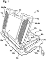
- FIG. 1 and FIG. 2 show an opened hand tool case 10a with a case base 12a, a case lid 14a and two connectors 36a.
- the connection devices 36a connect the case base body 12a to the case lid 14a without tools without tools.
- the connection devices 36a support the trunk lid 14a to be movable about an axis of rotation 38a between an illustrated open state and a closed state.
- the connection devices 36a connect the trunk main body 12a and the trunk lid 14a to transmit electric power partially conductively.
- the case base 12a and the case lid 14a are cup-shaped.
- the case base 12a has a handle 40a.
- the case lid 14a has a lighting device 18a.
- the lighting device 18a comprises a plurality of lighting means, light guides, not shown, and advantageously diffusers.
- the bulbs are designed as LEDs.
- the optical fibers pass a luminous flux emitted by the LEDs to the diffusers.
- the diffusers emit the luminous flux through a light exit surface 22a of the luminous device 18a.
- the light exit surface 22a forms part of an outer side 20a of the case lid 14a.
- a seal not shown, is arranged between a light emitting surface 22a having component and a light emitting surface 22a surrounding component.
- the light exit surface 22a is greater than 200 cm 2 .
- the lighting device 18a emits a luminous flux that is greater than 100 lumens.
- the case lid 14a has an additional module attachment 27a, which in an operating state attaches a functional additional module, in this case the lighting device 18a.
- the additional module attachment 27a not shown detent elements and electrically conductive contacts.
- the hand tool case 10a has an alignment device 24a.
- the alignment device 24a attaches the trunk lid 14a pivotally in different orientations relative to a standing plane 26a of the trunk body 12a.
- the alignment device 24a comprises a connection means 42a, a fastening element 44a and a latching means 46a.
- the fastener 44a pivotally secures the connecting means 42a to the trunk lid 14a.
- the locking means 46a fasten the connecting means 42a in different possible orientations with the case base body 12a.
- the connecting means 42a causes a fastening force between the case base body when the case lid 14a is open 12a and the case lid 14a, which prevents automatic closing of the case lid 14a.
- Other alignment devices that appear to be appropriate to the person skilled in the art are possible.
- the suitcase lid 14a has stacking means 23a.
- the stacking means 23a are formed as stiffeners of the case lid 14a. When a plurality of hand tool cases are stacked or when another force acts on the trunk lid 14a, the stacking means 23a transmit a force from a center of the trunk lid 14a to a side wall 47a of the trunk lid 14a. The side wall 47a of the case lid 14a transmits the force further toward the case main body 12a.
- the hand tool case 10a has electronics 16a, battery interfaces 17a, 28a, a mains input 30a, an electrical operating element 32a, a sealing means 34a, a media display unit 48a, a power distributor 50a and a device and accessory module 52a.
- the electronics 16a has a constant voltage source.
- the electronics 16a supply the lighting device 18a with a power which is transmitted by a constant voltage during operation.
- the electronics 16a could comprise a constant current source.
- the electronics 16a has a power switch which, in an operating state, interrupts a power supply of the media playback unit 48a.
- the electronics 16a is electrically operatively connected to the operating element 32a.
- the operating element 32a comprises two switches. It is arranged on the outer side 20a of the suitcase lid 14a. The one switch turns on and off the lighting device 18a. The other switch turns on and off the media playback unit 48a. Furthermore, the control element 32a comprises a non-illustrated magnetically actuated switch and a magnet. The magnetically actuated switch is arranged on the case lid 14a. The magnet is arranged on the case base body 12a. The magnetically actuated switch of the hand tool box 10a is actuated by a magnet of another hand tool box when stacking several hand tool cases. In this case, the electronics 16a, the lighting device 18a and the media playback unit 48a de-energized.
- the battery interfaces 17a, 28a attach and contact when charging and discharging a battery, not shown.
- the battery is designed as a hand tool battery.
- the first battery interface 17a is firmly connected to the case lid 14a.
- the second battery interface 28a is firmly connected to the case base body 12a.
- the battery interfaces 17a, 28a supply the electronics 16a with an electrical power removed from the battery during discharging.
- functional units supplied by the electronics 16a in this case the lighting device 18a and the media playback unit 48a, can be used independently of a power grid.
- the battery interfaces 17a, 28a have a charging electronics not shown for charging the battery.
- the mains input 30a receives power from a power grid during grid operation.
- the power input 30a has a power supply 54a and a cable extension 56a.
- the power supply unit 54a converts different mains voltages into a DC voltage, which transmits electrical power to the electronics 16a and to the battery interfaces 17a, 28a during mains operation.
- the Jardinauszug 56a has a power cord 58a, which is connected directly to a power network during network operation. An automatic of the cable extension 56a pulls the power cord 58a, triggered by an operator, automatically into the case base body 12a.
- the sealant 34a is formed as a labyrinth seal. It is arranged on a closing surface of the case lid 14a to the case base body 12a. When the case lid 14a is closed, the sealing means 34a effects a sealing action according to the protection class IP 52 between the case base body 12a and the case lid 14a. This largely prevents penetration of dirt and moisture into a receiving area 62a of the case base body 12a.
- the media playback unit 48a comprises two speakers 60a and a control unit, not shown.
- the media player 48a may output various sound media such as radio broadcasts and / or digital audio formats.
- the power distributor 50a has a multiple connector strip 64a.
- the multiple connector strip 64a is connected directly to the power input 30a.
- the power distributor 50a has a protection electronics, not shown.
- the device and accessory module 52a includes three attachment means 66a.
- the fastening means 66a are cup-shaped.
- One of the attachment means 66a is provided to secure a cordless drilling machine 68a.
- Two of the attachment means 66a are provided to secure batteries 70a.
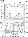
- FIG. 3 shows a hand tool case 10b according to the invention with a case base body 12b and a case lid 14b.
- the case lid 14b has electronics 16b.
- the case base 12b is separably connected to the case lid 14b.
- the case lid 14b also has a lighting device 18b.
- the lighting device 18b forms part of an outer side 20b of the case lid 14b.
- the electronics 16b supplies the lighting device 18b with electrical energy.
- the case base body 12b has a power inlet 30b.
- the case base body 12b has a power distributor 50b and an accessory module 52b for storing and securing a battery.
- the case main body 12b secures the modules mechanically and electrically separable, namely the modules are electrically connected via their non-illustrated power plug to the power inlet 30b.
- batteries can be loaded with closed lid 14b.
- the modules can be used against others that appear appropriate to the person skilled in the art Modules are exchanged.
- the power input 30b has a power supply 54b, a cable exhaust 56b and a power cord 58b.
- the hand tool case 10b has stacking means 23b.
- the stacking means 23b are partially formed on the case base body 12b and partially on the case lid 14b.
- the stacking means 23b are formed as stacking domes.
- the stacking means 23b transmit a force applied to a stacking surface directly to the case main body 12b.
- the FIG. 4 shows a hand tool case 10c according to the invention with a case base body 12c and a case lid 14c.
- the case base body 12c has a receiving region 62c for hand tools, handheld power tools and / or accessories.
- the suitcase lid 14c has an electronics 16c, a mains input 30c and a power distributor 50c.
- the case base body 12c is separable and electrically operatively isolated connected to the case lid 14c.
- the case lid 14c also has a lighting device 18c.
- the lighting device 18c forms part of an outer side 20c of the case lid 14c.
- the electronics 16c supplies the lighting device 18c with electrical energy.
- the power input 30c has a power supply 54c, a cable exhaust 56c and a power cord 58c.
- the hand tool case 10c could also have a battery interface, which is only intended to discharge a battery and / or a battery and to supply the electronics 16c.
Landscapes
- Engineering & Computer Science (AREA)
- Mechanical Engineering (AREA)
- General Engineering & Computer Science (AREA)
- Purses, Travelling Bags, Baskets, Or Suitcases (AREA)
- Non-Portable Lighting Devices Or Systems Thereof (AREA)
- Battery Mounting, Suspending (AREA)
- Arrangement Of Elements, Cooling, Sealing, Or The Like Of Lighting Devices (AREA)
- Workshop Equipment, Work Benches, Supports, Or Storage Means (AREA)
- Casings For Electric Apparatus (AREA)
Claims (11)
- Mallette à outils comprenant un corps de base de mallette (12a ; 12b ; 12c) et un couvercle de mallette (14a ; 14b ; 14c), le corps de base de mallette (12a ; 12b ; 12c) étant connecté de manière séparable au couvercle de mallette (14a ; 14b ; 14c) et présentant une région de réception (62c) pour au moins une machine-outil à main, ainsi qu'au moins une électronique (16a ; 16b ; 16c) qui est réalisée de manière à alimenter en puissance électrique une unité fonctionnelle réalisée sous forme de dispositif d'éclairage (18a ; 18b ; 18c), caractérisée en ce qu'au moins le couvercle de mallette (14a ; 14b ; 14c) présente au moins une interface de batterie (17a ; 17b ; 17c) et le dispositif d'éclairage (18a ; 18b ; 18c) qui sont connectés au moins en partie fixement au couvercle de mallette (14a ; 14b ; 14c), le dispositif d'éclairage (18a ; 18b ; 18c) formant au moins une partie d'un côté extérieur (20a ; 20b ; 20c) avec une surface de sortie de lumière (22a) sur le côté supérieur du couvercle de mallette (14a ; 14b ; 14c), et l'interface de batterie (17a ; 17b ; 17c) étant disposée sur un côté intérieur et étant prévue pour venir en contact avec une batterie de machine-outil à main, et en ce que l'électronique (16a ; 16b ; 16c) est connectée mécaniquement fixement au couvercle de mallette (14a ; 14b ; 14c).
- Mallette à outils selon l'une quelconque des revendications précédentes, caractérisée en ce que le couvercle de mallette (14a ; 14b ; 14c), dans un état fermé, recouvre la région de réception (62c) du corps de base de mallette (12a ; 12b ; 12c).
- Mallette à outils selon l'une quelconque des revendications précédentes, caractérisée par un dispositif d'éclairage (18a ; 18b ; 18c) et un dispositif d'alignement (24a ; 24b ; 24c) qui est prévu pour fixer de manière pivotante dans différentes orientations au moins une partie du corps de base de mallette (12a ; 12b ; 12c) ou du couvercle de mallette (14a ; 14b ; 14c) par rapport à un plan d'appui (26a) du corps de base de mallette (12a ; 12b ; 12c) ou du couvercle de mallette (14a ; 14b ; 14c).
- Mallette à outils au moins selon l'une quelconque des revendications précédentes, caractérisée en ce que la surface de sortie de lumière (22a) du dispositif d'éclairage (18a ; 18b ; 18c) est supérieure à 50 cm2.
- Mallette à outils selon l'une quelconque des revendications précédentes, caractérisée par un moyen d'empilement (23a ; 23b ; 23c) qui est prévu pour transmettre une force dans la direction du corps de base de mallette (12a ; 12b ; 12c) et/ou du couvercle de mallette (14a ; 14b ; 14c).
- Mallette à outils selon l'une quelconque des revendications précédentes, caractérisée en ce que le corps de base de mallette (12a) et/ou le couvercle de mallette (14a) présentent au moins une fixation de module supplémentaire (27a) qui est prévue pour fixer un module supplémentaire fonctionnel.
- Mallette à outils selon l'une quelconque des revendications précédentes, caractérisée par au moins une interface de batterie (28a ; 28b) qui est prévue pour alimenter au moins l'électronique (16a ; 16b) en énergie électrique.
- Mallette à outils selon l'une quelconque des revendications précédentes, caractérisée par une entrée de réseau (30a ; 30b ; 30c) qui est prévue pour recevoir de l'énergie provenant d'un réseau électrique.
- Mallette à outils selon l'une quelconque des revendications précédentes, caractérisée par un élément de commande électrique (32a ; 32b ; 32c) qui est disposé de manière à pouvoir être commandé lorsque le couvercle de mallette (14a ; 14b ; 14c) est fermé.
- Mallette à outils selon la revendication 9, caractérisée en ce que l'élément de commande (32a ; 32b ; 32c) est prévu pour être actionné par un empilement de plusieurs mallettes à outils.
- Couvercle de mallette d'une mallette à outils (10a ; 10b ; 10c) selon la revendication 1, comprenant au moins une électronique (16a ; 16b ; 16c) qui est réalisée de manière à alimenter en puissance électrique une unité fonctionnelle réalisée sous forme de dispositif d'éclairage (18a ; 18b ; 18c), caractérisé en ce que le couvercle de mallette (14a ; 14b ; 14c) présente au moins une interface de batterie (17a ; 17b ; 17c) et un dispositif d'éclairage (18a ; 18b ; 18c) qui sont reliés au moins en partie fixement au couvercle de mallette (14a ; 14b ; 14c), le dispositif d'éclairage (18a ; 18b ; 18c) formant au moins une partie d'un côté extérieur (20a ; 20b ; 20c) avec une surface de sortie de lumière (22a) sur le côté supérieur du couvercle de mallette (14a ; 14b ; 14c), et l'interface de batterie (17a ; 17b ; 17c) étant disposée sur un côté intérieur et étant prévue pour venir en contact avec une batterie de machine-outil à main, et en ce que l'électronique (16a ; 16b ; 16c) est connectée mécaniquement fixement au couvercle de mallette (14a ; 14b ; 14c).
Applications Claiming Priority (3)
| Application Number | Priority Date | Filing Date | Title |
|---|---|---|---|
| DE102010029342 | 2010-05-27 | ||
| DE102011002409A DE102011002409A1 (de) | 2010-05-27 | 2011-01-03 | Handwerkzeugkoffer |
| PCT/EP2011/055267 WO2011147625A1 (fr) | 2010-05-27 | 2011-04-05 | Mallette à outils |
Publications (2)
| Publication Number | Publication Date |
|---|---|
| EP2576149A1 EP2576149A1 (fr) | 2013-04-10 |
| EP2576149B1 true EP2576149B1 (fr) | 2018-03-07 |
Family
ID=44924815
Family Applications (3)
| Application Number | Title | Priority Date | Filing Date |
|---|---|---|---|
| EP11712847.0A Active EP2576150B1 (fr) | 2010-05-27 | 2011-04-05 | Mallette à outils |
| EP11712548.4A Active EP2576149B1 (fr) | 2010-05-27 | 2011-04-05 | Mallette à outils |
| EP11713746.3A Active EP2576151B1 (fr) | 2010-05-27 | 2011-04-05 | Mallette à outils |
Family Applications Before (1)
| Application Number | Title | Priority Date | Filing Date |
|---|---|---|---|
| EP11712847.0A Active EP2576150B1 (fr) | 2010-05-27 | 2011-04-05 | Mallette à outils |
Family Applications After (1)
| Application Number | Title | Priority Date | Filing Date |
|---|---|---|---|
| EP11713746.3A Active EP2576151B1 (fr) | 2010-05-27 | 2011-04-05 | Mallette à outils |
Country Status (5)
| Country | Link |
|---|---|
| US (3) | US10144124B2 (fr) |
| EP (3) | EP2576150B1 (fr) |
| CN (3) | CN102905858B (fr) |
| DE (1) | DE102011002409A1 (fr) |
| WO (3) | WO2011147625A1 (fr) |
Families Citing this family (47)
| Publication number | Priority date | Publication date | Assignee | Title |
|---|---|---|---|---|
| DE102009027571B4 (de) * | 2009-07-09 | 2025-11-06 | Robert Bosch Gmbh | Akkuladekoffer |
| GB2487461B (en) * | 2011-01-03 | 2013-08-07 | Bosch Gmbh Robert | Handtool box with lighting arrangement |
| DE102011006871B4 (de) | 2011-01-03 | 2024-08-08 | Robert Bosch Gmbh | Handwerkzeugkoffer mit einer Leuchtvorrichtung |
| DE102012204407B4 (de) * | 2012-03-20 | 2024-08-01 | Robert Bosch Gmbh | System zumindest mit einem Handwerkzeugkoffer und einem Baustellenradio |
| DE102012111328A1 (de) * | 2012-11-23 | 2014-05-28 | Vorwerk & Co. Interholding Gmbh | Koffer für akkumulatorbetriebene Werkzeuge |
| USD710104S1 (en) * | 2013-01-29 | 2014-08-05 | Tivoly, Inc. | Tool container |
| US8985335B1 (en) * | 2013-02-19 | 2015-03-24 | Stephen J. Fisher | Magnetically mountable tray device |
| US20140332423A1 (en) * | 2013-05-07 | 2014-11-13 | Hong-Jen Lee | Tool box |
| USD733429S1 (en) * | 2013-10-08 | 2015-07-07 | Jean-Pierre Grenier | Case |
| US20170063114A1 (en) * | 2013-11-15 | 2017-03-02 | Christian Fitch BRIERE | Multi-port battery charging apparatus, system and kit |
| US9402420B2 (en) * | 2014-02-15 | 2016-08-02 | Colby Barrett | Smoking accessory kit system |
| DE102014010377A1 (de) * | 2014-07-12 | 2016-01-14 | Festool Gmbh | Stapelanordnung und Transportbehälter mit Busschnittstellen |
| DK3166758T3 (en) | 2014-07-12 | 2019-04-15 | Festool Gmbh | Stacking device and transport container with bus interfaces |
| DE102014010378A1 (de) * | 2014-07-12 | 2016-01-14 | Festool Gmbh | Transportbehälter mit einem Behältereinsatz |
| US10575417B2 (en) * | 2014-09-08 | 2020-02-25 | The Stanley Works Israel Ltd. | Jobsite communications center |
| DE102014112957A1 (de) * | 2014-09-09 | 2016-03-10 | Vorwerk & Co. Interholding Gmbh | Behälter zur Aufbewahrung mindestens eines mit einem Akkumulator angetriebenen Gerätes |
| DE102014225510A1 (de) | 2014-12-11 | 2016-06-16 | Adolf Würth GmbH & Co. KG | Koffer zum Aufnehmen von Werkzeugen oder Kleinteilen |
| USD779822S1 (en) | 2015-09-03 | 2017-02-28 | Plasticase, Inc. | Case |
| DE102016105457A1 (de) * | 2016-01-07 | 2017-07-13 | Festool Gmbh | Übertragungseinrichtung und damit ausgestatteter Stapelbehälter |
| DE102016105458A1 (de) * | 2016-01-07 | 2017-07-13 | Festool Gmbh | Übertragungseinrichtung und damit ausgestatteter Stapelbehälter |
| DE202016105423U1 (de) | 2016-09-29 | 2016-10-18 | Michael Kralitschek | Werkzeugkoffer und Beleuchtungseinrichtung für Werkzeugkoffer |
| CN106426044B (zh) * | 2016-10-24 | 2018-11-02 | 郑小龙 | 一种具有指纹识别和照明功能的检测工具箱 |
| CN107860954A (zh) * | 2017-10-30 | 2018-03-30 | 四川行之智汇知识产权运营有限公司 | 一种移动式用电信息采集设备 |
| US10801263B2 (en) * | 2018-02-23 | 2020-10-13 | Werner Co. | Ladder with top for holding an impact driver and method |
| DE102018206879A1 (de) * | 2018-05-04 | 2019-11-07 | Robert Bosch Gmbh | Werkzeugaufbewahrungsvorrichtung |
| US10752403B1 (en) * | 2018-05-23 | 2020-08-25 | Dennis Rinear | Vehicle box organizer |
| US10574067B1 (en) * | 2018-07-18 | 2020-02-25 | James Hanson | Multi-purpose utility box |
| CN110946000B (zh) | 2018-09-27 | 2022-03-01 | 南京德朔实业有限公司 | 割草机 |
| EP3821692B1 (fr) | 2018-09-27 | 2024-07-31 | Nanjing Chervon Industry Co., Ltd. | Tondeuse à gazon |
| CN109249365A (zh) * | 2018-11-20 | 2019-01-22 | 国网辽宁省电力有限公司葫芦岛供电公司 | 一种便携式运维组合工具箱 |
| USD872479S1 (en) * | 2018-12-04 | 2020-01-14 | Black & Decker Inc. | Tool container |
| USD873017S1 (en) * | 2018-12-04 | 2020-01-21 | Black & Decker Inc. | Tool container |
| CN113518694B (zh) | 2019-03-06 | 2024-06-18 | 米沃奇电动工具公司 | 具有发光部件的储存单元 |
| USD995569S1 (en) | 2019-04-18 | 2023-08-15 | Nanjing Chervon Industry Co., Ltd. | Mower blade assembly |
| CN110181472A (zh) * | 2019-05-10 | 2019-08-30 | 国网冀北电力有限公司承德供电公司 | 安全工器具箱 |
| USD963337S1 (en) | 2019-07-31 | 2022-09-13 | Plasticase, Inc. | Case with an extendable handle |
| USD924535S1 (en) | 2019-10-28 | 2021-07-06 | Vaultek Safe Inc. | Lock box |
| CN113770992A (zh) * | 2021-09-28 | 2021-12-10 | 广东电网有限责任公司东莞供电局 | 一种放置电力维修工具的便携式绝缘垫 |
| US11473771B1 (en) | 2021-10-19 | 2022-10-18 | Terry Kavanagh | Illuminated wall composition pan |
| US11858114B2 (en) | 2021-11-10 | 2024-01-02 | Techtronic Cordless Gp | Carrying case for a power tool |
| US11738914B2 (en) | 2021-11-18 | 2023-08-29 | Yeti Coolers, Llc | Container and latching system |
| US12512635B2 (en) * | 2022-01-25 | 2025-12-30 | The Stanley Works Israel Ltd. | Stackable power outlet box |
| USD1087186S1 (en) * | 2022-08-03 | 2025-08-05 | Festool Gmbh | Circular saw with cover |
| US12502854B2 (en) * | 2022-09-27 | 2025-12-23 | Illinois Tool Works Inc. | Tire repair system |
| DE102022210256A1 (de) * | 2022-09-28 | 2024-03-28 | Robert Bosch Gesellschaft mit beschränkter Haftung | Werkzeugkoffer für eine Handwerkzeugmaschine |
| USD1066212S1 (en) * | 2022-09-30 | 2025-03-11 | Illinois Tool Works Inc. | Tire repair system |
| US20250309665A1 (en) * | 2024-03-28 | 2025-10-02 | Keith Rouse | Battery charging toolbox assembly |
Citations (7)
| Publication number | Priority date | Publication date | Assignee | Title |
|---|---|---|---|---|
| US6053315A (en) * | 1998-07-10 | 2000-04-25 | Yao; Ghing Hsiu | Tool box having a rotatable light |
| US6237767B1 (en) * | 2000-06-07 | 2001-05-29 | Tze-Ming Lee | Tool box |
| US6254251B1 (en) * | 1999-09-29 | 2001-07-03 | Willie J. Washington | Portable tool storage box |
| US20040125597A1 (en) * | 2002-12-31 | 2004-07-01 | Zag Industries Ltd. | Tool box with light |
| US7055983B1 (en) * | 2004-06-17 | 2006-06-06 | Brooks & Baker Llc | Tackle and storage box with rotatable light |
| CN2842201Y (zh) * | 2005-06-13 | 2006-11-29 | 谢智庆 | 承置工具的照明装置 |
| CN201132309Y (zh) * | 2007-08-29 | 2008-10-15 | 苏鑫 | 照明工具箱 |
Family Cites Families (21)
| Publication number | Priority date | Publication date | Assignee | Title |
|---|---|---|---|---|
| US1945375A (en) * | 1932-04-21 | 1934-01-30 | Louis A Pazandak | Box lid holder |
| US2061413A (en) | 1935-12-30 | 1936-11-17 | Frank P Tropea | Box lid holding device |
| CH581840A5 (fr) * | 1974-06-28 | 1976-11-15 | Gretag Ag | |
| DE8317956U1 (de) | 1983-06-21 | 1984-01-12 | Žižek, Jože, Dipl.oec, 7737 Bad Dürrheim | Mehrzweck-Hobby-Box mit Deckelabstuetzvorrichtung |
| DE4443521C1 (de) * | 1994-12-07 | 1996-01-04 | Daimler Benz Ag | Abdeckbarer Behälter für Fahrzeuge |
| US6267240B1 (en) | 1996-03-01 | 2001-07-31 | Roscoe Callaway | Illuminated portable tool box |
| US5624029A (en) * | 1996-06-18 | 1997-04-29 | Shih; Yi L. | Tool box with a lighting apparatus |
| US7036267B2 (en) * | 1997-10-29 | 2006-05-02 | Klein Darrel J | Sporting apparatus suited for fishing and hunting |
| US6244064B1 (en) * | 1998-11-23 | 2001-06-12 | Arthur Powell | Combination toolbox-cooler device |
| US6662945B1 (en) * | 2002-11-04 | 2003-12-16 | Joinery Industrial Co., Ltd. | Toolbox with stereo |
| TWI222921B (en) * | 2003-05-14 | 2004-11-01 | Tai-Tzuo Chen | Tool storage apparatus with illumination structure |
| CN1914008A (zh) | 2003-12-24 | 2007-02-14 | 麦克斯泰克制造公司 | 便携式工具箱和工作站 |
| US6981778B2 (en) * | 2004-01-16 | 2006-01-03 | Artograph, Inc. | Portable light box |
| WO2005107516A2 (fr) | 2004-05-03 | 2005-11-17 | Nomis, Llc | Centre de travail / table de serrage et système de rangement |
| JP4534774B2 (ja) | 2005-01-31 | 2010-09-01 | ブラザー工業株式会社 | ドア装置および当該ドア装置を備えた工作機械 |
| JP2006205323A (ja) * | 2005-01-31 | 2006-08-10 | Hitachi Koki Co Ltd | 工具収納ケース |
| US7735646B2 (en) * | 2006-06-29 | 2010-06-15 | Scaletta Samuel L | Toolbox with wheel chocks as supports |
| US20080035507A1 (en) * | 2006-08-14 | 2008-02-14 | Collister Kenneth F | Power Tool Case |
| US7878675B2 (en) * | 2006-11-24 | 2011-02-01 | Bruce L. Finn | Fashion illumination system |
| US8083111B2 (en) * | 2009-03-19 | 2011-12-27 | Lase John J | Tractor mounted toolbox |
| DE102009027573A1 (de) | 2009-07-09 | 2011-01-13 | Robert Bosch Gmbh | Werkzeugkoffer, insbesondere Handwerkzeugkoffer |
-
2011
- 2011-01-03 DE DE102011002409A patent/DE102011002409A1/de not_active Withdrawn
- 2011-04-05 US US13/699,582 patent/US10144124B2/en active Active
- 2011-04-05 WO PCT/EP2011/055267 patent/WO2011147625A1/fr not_active Ceased
- 2011-04-05 CN CN201180026007.5A patent/CN102905858B/zh active Active
- 2011-04-05 EP EP11712847.0A patent/EP2576150B1/fr active Active
- 2011-04-05 EP EP11712548.4A patent/EP2576149B1/fr active Active
- 2011-04-05 CN CN201180025927.5A patent/CN102905856B/zh active Active
- 2011-04-05 US US13/699,795 patent/US10539317B2/en active Active
- 2011-04-05 WO PCT/EP2011/055269 patent/WO2011147626A1/fr not_active Ceased
- 2011-04-05 CN CN201180025958.0A patent/CN102905857B/zh active Active
- 2011-04-05 US US13/699,808 patent/US9381639B2/en active Active
- 2011-04-05 WO PCT/EP2011/055260 patent/WO2011147624A1/fr not_active Ceased
- 2011-04-05 EP EP11713746.3A patent/EP2576151B1/fr active Active
Patent Citations (7)
| Publication number | Priority date | Publication date | Assignee | Title |
|---|---|---|---|---|
| US6053315A (en) * | 1998-07-10 | 2000-04-25 | Yao; Ghing Hsiu | Tool box having a rotatable light |
| US6254251B1 (en) * | 1999-09-29 | 2001-07-03 | Willie J. Washington | Portable tool storage box |
| US6237767B1 (en) * | 2000-06-07 | 2001-05-29 | Tze-Ming Lee | Tool box |
| US20040125597A1 (en) * | 2002-12-31 | 2004-07-01 | Zag Industries Ltd. | Tool box with light |
| US7055983B1 (en) * | 2004-06-17 | 2006-06-06 | Brooks & Baker Llc | Tackle and storage box with rotatable light |
| CN2842201Y (zh) * | 2005-06-13 | 2006-11-29 | 谢智庆 | 承置工具的照明装置 |
| CN201132309Y (zh) * | 2007-08-29 | 2008-10-15 | 苏鑫 | 照明工具箱 |
Also Published As
| Publication number | Publication date |
|---|---|
| US10539317B2 (en) | 2020-01-21 |
| CN102905858A (zh) | 2013-01-30 |
| EP2576149A1 (fr) | 2013-04-10 |
| CN102905856A (zh) | 2013-01-30 |
| CN102905856B (zh) | 2018-11-30 |
| US9381639B2 (en) | 2016-07-05 |
| US20130128560A1 (en) | 2013-05-23 |
| EP2576151B1 (fr) | 2017-06-14 |
| EP2576150A1 (fr) | 2013-04-10 |
| EP2576151A1 (fr) | 2013-04-10 |
| US20130155657A1 (en) | 2013-06-20 |
| US10144124B2 (en) | 2018-12-04 |
| CN102905858B (zh) | 2016-09-07 |
| DE102011002409A1 (de) | 2011-12-01 |
| WO2011147625A1 (fr) | 2011-12-01 |
| US20130135846A1 (en) | 2013-05-30 |
| CN102905857B (zh) | 2018-10-19 |
| CN102905857A (zh) | 2013-01-30 |
| WO2011147626A1 (fr) | 2011-12-01 |
| EP2576150B1 (fr) | 2017-08-23 |
| WO2011147624A1 (fr) | 2011-12-01 |
Similar Documents
| Publication | Publication Date | Title |
|---|---|---|
| EP2576149B1 (fr) | Mallette à outils | |
| DE102011077112A1 (de) | Handwerkzeugaufbewahrungsvorrichtung | |
| EP1889693B1 (fr) | Visseuse sans fil avec socle chargeur | |
| EP2451616B1 (fr) | Coffre à outils, en particulier pour outils à main | |
| US6817495B1 (en) | Portable tool box | |
| DE102012220837A1 (de) | Baustellenradio | |
| DE10119061A1 (de) | Schneidewerkzeuge mit Beleuchtung | |
| DE102010003283A1 (de) | Handwerkzeugmaschinenakkuvorrichtung | |
| DE102011006871A1 (de) | Handwerkzeugkoffer | |
| DE102012213047A1 (de) | Handwerkzeugkoffer | |
| WO2019211063A1 (fr) | Bloc d'accumulateurs | |
| EP2591285B1 (fr) | Appareil d'éclairage manuel | |
| US20180054082A1 (en) | Battery powered electrical outlet | |
| MX2007004311A (es) | Caja de camion con cubierta de despeje reducido y acceso para paso directo de cable electrico. | |
| GB2433711A (en) | Suction device for a handheld power tool | |
| US20090097250A1 (en) | Integrated battery charging work light electrical distribution system | |
| DE202018006402U1 (de) | Akkupack | |
| KR200330635Y1 (ko) | 핸드드릴에 부착되는 나사 저장 통 | |
| WO2025133241A1 (fr) | Module d'éclairage pour machine-outil portative, module de machine-outil et kit de construction | |
| DE102010010344A1 (de) | Transportbehälter mit Audio-Gerät |
Legal Events
| Date | Code | Title | Description |
|---|---|---|---|
| PUAI | Public reference made under article 153(3) epc to a published international application that has entered the european phase |
Free format text: ORIGINAL CODE: 0009012 |
|
| 17P | Request for examination filed |
Effective date: 20130102 |
|
| AK | Designated contracting states |
Kind code of ref document: A1 Designated state(s): AL AT BE BG CH CY CZ DE DK EE ES FI FR GB GR HR HU IE IS IT LI LT LU LV MC MK MT NL NO PL PT RO RS SE SI SK SM TR |
|
| DAX | Request for extension of the european patent (deleted) | ||
| 17Q | First examination report despatched |
Effective date: 20151021 |
|
| GRAP | Despatch of communication of intention to grant a patent |
Free format text: ORIGINAL CODE: EPIDOSNIGR1 |
|
| INTG | Intention to grant announced |
Effective date: 20171214 |
|
| GRAS | Grant fee paid |
Free format text: ORIGINAL CODE: EPIDOSNIGR3 |
|
| GRAA | (expected) grant |
Free format text: ORIGINAL CODE: 0009210 |
|
| AK | Designated contracting states |
Kind code of ref document: B1 Designated state(s): AL AT BE BG CH CY CZ DE DK EE ES FI FR GB GR HR HU IE IS IT LI LT LU LV MC MK MT NL NO PL PT RO RS SE SI SK SM TR |
|
| REG | Reference to a national code |
Ref country code: GB Ref legal event code: FG4D Free format text: NOT ENGLISH |
|
| REG | Reference to a national code |
Ref country code: CH Ref legal event code: EP Ref country code: AT Ref legal event code: REF Ref document number: 976036 Country of ref document: AT Kind code of ref document: T Effective date: 20180315 |
|
| REG | Reference to a national code |
Ref country code: IE Ref legal event code: FG4D Free format text: LANGUAGE OF EP DOCUMENT: GERMAN |
|
| REG | Reference to a national code |
Ref country code: DE Ref legal event code: R096 Ref document number: 502011013860 Country of ref document: DE |
|
| REG | Reference to a national code |
Ref country code: FR Ref legal event code: PLFP Year of fee payment: 8 |
|
| REG | Reference to a national code |
Ref country code: NL Ref legal event code: MP Effective date: 20180307 |
|
| REG | Reference to a national code |
Ref country code: LT Ref legal event code: MG4D |
|
| PG25 | Lapsed in a contracting state [announced via postgrant information from national office to epo] |
Ref country code: HR Free format text: LAPSE BECAUSE OF FAILURE TO SUBMIT A TRANSLATION OF THE DESCRIPTION OR TO PAY THE FEE WITHIN THE PRESCRIBED TIME-LIMIT Effective date: 20180307 Ref country code: LT Free format text: LAPSE BECAUSE OF FAILURE TO SUBMIT A TRANSLATION OF THE DESCRIPTION OR TO PAY THE FEE WITHIN THE PRESCRIBED TIME-LIMIT Effective date: 20180307 Ref country code: CY Free format text: LAPSE BECAUSE OF FAILURE TO SUBMIT A TRANSLATION OF THE DESCRIPTION OR TO PAY THE FEE WITHIN THE PRESCRIBED TIME-LIMIT Effective date: 20180307 Ref country code: NO Free format text: LAPSE BECAUSE OF FAILURE TO SUBMIT A TRANSLATION OF THE DESCRIPTION OR TO PAY THE FEE WITHIN THE PRESCRIBED TIME-LIMIT Effective date: 20180607 Ref country code: ES Free format text: LAPSE BECAUSE OF FAILURE TO SUBMIT A TRANSLATION OF THE DESCRIPTION OR TO PAY THE FEE WITHIN THE PRESCRIBED TIME-LIMIT Effective date: 20180307 Ref country code: FI Free format text: LAPSE BECAUSE OF FAILURE TO SUBMIT A TRANSLATION OF THE DESCRIPTION OR TO PAY THE FEE WITHIN THE PRESCRIBED TIME-LIMIT Effective date: 20180307 |
|
| PG25 | Lapsed in a contracting state [announced via postgrant information from national office to epo] |
Ref country code: LV Free format text: LAPSE BECAUSE OF FAILURE TO SUBMIT A TRANSLATION OF THE DESCRIPTION OR TO PAY THE FEE WITHIN THE PRESCRIBED TIME-LIMIT Effective date: 20180307 Ref country code: SE Free format text: LAPSE BECAUSE OF FAILURE TO SUBMIT A TRANSLATION OF THE DESCRIPTION OR TO PAY THE FEE WITHIN THE PRESCRIBED TIME-LIMIT Effective date: 20180307 Ref country code: GR Free format text: LAPSE BECAUSE OF FAILURE TO SUBMIT A TRANSLATION OF THE DESCRIPTION OR TO PAY THE FEE WITHIN THE PRESCRIBED TIME-LIMIT Effective date: 20180608 Ref country code: RS Free format text: LAPSE BECAUSE OF FAILURE TO SUBMIT A TRANSLATION OF THE DESCRIPTION OR TO PAY THE FEE WITHIN THE PRESCRIBED TIME-LIMIT Effective date: 20180307 Ref country code: BG Free format text: LAPSE BECAUSE OF FAILURE TO SUBMIT A TRANSLATION OF THE DESCRIPTION OR TO PAY THE FEE WITHIN THE PRESCRIBED TIME-LIMIT Effective date: 20180607 |
|
| PG25 | Lapsed in a contracting state [announced via postgrant information from national office to epo] |
Ref country code: MT Free format text: LAPSE BECAUSE OF FAILURE TO SUBMIT A TRANSLATION OF THE DESCRIPTION OR TO PAY THE FEE WITHIN THE PRESCRIBED TIME-LIMIT Effective date: 20180307 |
|
| PG25 | Lapsed in a contracting state [announced via postgrant information from national office to epo] |
Ref country code: AL Free format text: LAPSE BECAUSE OF FAILURE TO SUBMIT A TRANSLATION OF THE DESCRIPTION OR TO PAY THE FEE WITHIN THE PRESCRIBED TIME-LIMIT Effective date: 20180307 Ref country code: EE Free format text: LAPSE BECAUSE OF FAILURE TO SUBMIT A TRANSLATION OF THE DESCRIPTION OR TO PAY THE FEE WITHIN THE PRESCRIBED TIME-LIMIT Effective date: 20180307 Ref country code: PL Free format text: LAPSE BECAUSE OF FAILURE TO SUBMIT A TRANSLATION OF THE DESCRIPTION OR TO PAY THE FEE WITHIN THE PRESCRIBED TIME-LIMIT Effective date: 20180307 Ref country code: RO Free format text: LAPSE BECAUSE OF FAILURE TO SUBMIT A TRANSLATION OF THE DESCRIPTION OR TO PAY THE FEE WITHIN THE PRESCRIBED TIME-LIMIT Effective date: 20180307 Ref country code: IT Free format text: LAPSE BECAUSE OF FAILURE TO SUBMIT A TRANSLATION OF THE DESCRIPTION OR TO PAY THE FEE WITHIN THE PRESCRIBED TIME-LIMIT Effective date: 20180307 Ref country code: NL Free format text: LAPSE BECAUSE OF FAILURE TO SUBMIT A TRANSLATION OF THE DESCRIPTION OR TO PAY THE FEE WITHIN THE PRESCRIBED TIME-LIMIT Effective date: 20180307 |
|
| PG25 | Lapsed in a contracting state [announced via postgrant information from national office to epo] |
Ref country code: SM Free format text: LAPSE BECAUSE OF FAILURE TO SUBMIT A TRANSLATION OF THE DESCRIPTION OR TO PAY THE FEE WITHIN THE PRESCRIBED TIME-LIMIT Effective date: 20180307 Ref country code: CZ Free format text: LAPSE BECAUSE OF FAILURE TO SUBMIT A TRANSLATION OF THE DESCRIPTION OR TO PAY THE FEE WITHIN THE PRESCRIBED TIME-LIMIT Effective date: 20180307 Ref country code: SK Free format text: LAPSE BECAUSE OF FAILURE TO SUBMIT A TRANSLATION OF THE DESCRIPTION OR TO PAY THE FEE WITHIN THE PRESCRIBED TIME-LIMIT Effective date: 20180307 |
|
| REG | Reference to a national code |
Ref country code: CH Ref legal event code: PL |
|
| REG | Reference to a national code |
Ref country code: DE Ref legal event code: R097 Ref document number: 502011013860 Country of ref document: DE |
|
| REG | Reference to a national code |
Ref country code: BE Ref legal event code: MM Effective date: 20180430 |
|
| PG25 | Lapsed in a contracting state [announced via postgrant information from national office to epo] |
Ref country code: PT Free format text: LAPSE BECAUSE OF FAILURE TO SUBMIT A TRANSLATION OF THE DESCRIPTION OR TO PAY THE FEE WITHIN THE PRESCRIBED TIME-LIMIT Effective date: 20180709 |
|
| PLBE | No opposition filed within time limit |
Free format text: ORIGINAL CODE: 0009261 |
|
| STAA | Information on the status of an ep patent application or granted ep patent |
Free format text: STATUS: NO OPPOSITION FILED WITHIN TIME LIMIT |
|
| REG | Reference to a national code |
Ref country code: IE Ref legal event code: MM4A |
|
| PG25 | Lapsed in a contracting state [announced via postgrant information from national office to epo] |
Ref country code: LU Free format text: LAPSE BECAUSE OF NON-PAYMENT OF DUE FEES Effective date: 20180405 Ref country code: DK Free format text: LAPSE BECAUSE OF FAILURE TO SUBMIT A TRANSLATION OF THE DESCRIPTION OR TO PAY THE FEE WITHIN THE PRESCRIBED TIME-LIMIT Effective date: 20180307 Ref country code: MC Free format text: LAPSE BECAUSE OF FAILURE TO SUBMIT A TRANSLATION OF THE DESCRIPTION OR TO PAY THE FEE WITHIN THE PRESCRIBED TIME-LIMIT Effective date: 20180307 |
|
| 26N | No opposition filed |
Effective date: 20181210 |
|
| PG25 | Lapsed in a contracting state [announced via postgrant information from national office to epo] |
Ref country code: CH Free format text: LAPSE BECAUSE OF NON-PAYMENT OF DUE FEES Effective date: 20180430 Ref country code: LI Free format text: LAPSE BECAUSE OF NON-PAYMENT OF DUE FEES Effective date: 20180430 Ref country code: BE Free format text: LAPSE BECAUSE OF NON-PAYMENT OF DUE FEES Effective date: 20180430 Ref country code: SI Free format text: LAPSE BECAUSE OF FAILURE TO SUBMIT A TRANSLATION OF THE DESCRIPTION OR TO PAY THE FEE WITHIN THE PRESCRIBED TIME-LIMIT Effective date: 20180307 |
|
| PG25 | Lapsed in a contracting state [announced via postgrant information from national office to epo] |
Ref country code: IE Free format text: LAPSE BECAUSE OF NON-PAYMENT OF DUE FEES Effective date: 20180405 |
|
| REG | Reference to a national code |
Ref country code: AT Ref legal event code: MM01 Ref document number: 976036 Country of ref document: AT Kind code of ref document: T Effective date: 20180405 |
|
| PG25 | Lapsed in a contracting state [announced via postgrant information from national office to epo] |
Ref country code: AT Free format text: LAPSE BECAUSE OF NON-PAYMENT OF DUE FEES Effective date: 20180405 |
|
| PG25 | Lapsed in a contracting state [announced via postgrant information from national office to epo] |
Ref country code: TR Free format text: LAPSE BECAUSE OF FAILURE TO SUBMIT A TRANSLATION OF THE DESCRIPTION OR TO PAY THE FEE WITHIN THE PRESCRIBED TIME-LIMIT Effective date: 20180307 |
|
| PG25 | Lapsed in a contracting state [announced via postgrant information from national office to epo] |
Ref country code: HU Free format text: LAPSE BECAUSE OF FAILURE TO SUBMIT A TRANSLATION OF THE DESCRIPTION OR TO PAY THE FEE WITHIN THE PRESCRIBED TIME-LIMIT; INVALID AB INITIO Effective date: 20110405 |
|
| PG25 | Lapsed in a contracting state [announced via postgrant information from national office to epo] |
Ref country code: MK Free format text: LAPSE BECAUSE OF NON-PAYMENT OF DUE FEES Effective date: 20180307 |
|
| PG25 | Lapsed in a contracting state [announced via postgrant information from national office to epo] |
Ref country code: IS Free format text: LAPSE BECAUSE OF FAILURE TO SUBMIT A TRANSLATION OF THE DESCRIPTION OR TO PAY THE FEE WITHIN THE PRESCRIBED TIME-LIMIT Effective date: 20180707 |
|
| REG | Reference to a national code |
Ref country code: DE Ref legal event code: R084 Ref document number: 502011013860 Country of ref document: DE |
|
| PGFP | Annual fee paid to national office [announced via postgrant information from national office to epo] |
Ref country code: DE Payment date: 20240619 Year of fee payment: 14 |
|
| PGFP | Annual fee paid to national office [announced via postgrant information from national office to epo] |
Ref country code: GB Payment date: 20250423 Year of fee payment: 15 |
|
| PGFP | Annual fee paid to national office [announced via postgrant information from national office to epo] |
Ref country code: FR Payment date: 20250422 Year of fee payment: 15 |
|
| REG | Reference to a national code |
Ref country code: DE Ref legal event code: R119 Ref document number: 502011013860 Country of ref document: DE |
|
| PG25 | Lapsed in a contracting state [announced via postgrant information from national office to epo] |
Ref country code: DE Free format text: LAPSE BECAUSE OF NON-PAYMENT OF DUE FEES Effective date: 20251104 |