EP2576196B1 - Handbetätigbare kniehebelpresse mit grossem arbeitshub - Google Patents
Handbetätigbare kniehebelpresse mit grossem arbeitshub Download PDFInfo
- Publication number
- EP2576196B1 EP2576196B1 EP11727796.2A EP11727796A EP2576196B1 EP 2576196 B1 EP2576196 B1 EP 2576196B1 EP 11727796 A EP11727796 A EP 11727796A EP 2576196 B1 EP2576196 B1 EP 2576196B1
- Authority
- EP
- European Patent Office
- Prior art keywords
- knuckle
- joint
- press
- lever
- carrier element
- Prior art date
- Legal status (The legal status is an assumption and is not a legal conclusion. Google has not performed a legal analysis and makes no representation as to the accuracy of the status listed.)
- Not-in-force
Links
- 210000003127 knee Anatomy 0.000 description 9
- 230000007423 decrease Effects 0.000 description 5
- 238000004519 manufacturing process Methods 0.000 description 2
- 239000004753 textile Substances 0.000 description 2
- 240000006829 Ficus sundaica Species 0.000 description 1
- 238000000418 atomic force spectrum Methods 0.000 description 1
- 230000005540 biological transmission Effects 0.000 description 1
- 230000015572 biosynthetic process Effects 0.000 description 1
- 238000006243 chemical reaction Methods 0.000 description 1
- 238000010276 construction Methods 0.000 description 1
- 238000006073 displacement reaction Methods 0.000 description 1
- 230000000694 effects Effects 0.000 description 1
- 238000001125 extrusion Methods 0.000 description 1
- 210000003746 feather Anatomy 0.000 description 1
- 238000004904 shortening Methods 0.000 description 1
Images

Classifications
-
- B—PERFORMING OPERATIONS; TRANSPORTING
- B30—PRESSES
- B30B—PRESSES IN GENERAL
- B30B1/00—Presses, using a press ram, characterised by the features of the drive therefor, pressure being transmitted directly, or through simple thrust or tension members only, to the press ram or platen
- B30B1/10—Presses, using a press ram, characterised by the features of the drive therefor, pressure being transmitted directly, or through simple thrust or tension members only, to the press ram or platen by toggle mechanism
- B30B1/12—Presses, using a press ram, characterised by the features of the drive therefor, pressure being transmitted directly, or through simple thrust or tension members only, to the press ram or platen by toggle mechanism operated by hand or foot
-
- B—PERFORMING OPERATIONS; TRANSPORTING
- B30—PRESSES
- B30B—PRESSES IN GENERAL
- B30B1/00—Presses, using a press ram, characterised by the features of the drive therefor, pressure being transmitted directly, or through simple thrust or tension members only, to the press ram or platen
- B30B1/10—Presses, using a press ram, characterised by the features of the drive therefor, pressure being transmitted directly, or through simple thrust or tension members only, to the press ram or platen by toggle mechanism
- B30B1/14—Presses, using a press ram, characterised by the features of the drive therefor, pressure being transmitted directly, or through simple thrust or tension members only, to the press ram or platen by toggle mechanism operated by cams, eccentrics, or cranks
Definitions
- the invention relates to a hand-operated toggle press with a stand, a press ram and a pivotable about an axis actuating lever, with which the press ram can be brought into an upper and a lower position, in particular an upper and a lower dead center.
- the respective drive a toggle press can be done electromechanically, hydraulically, pneumatically or by hand, usually via a lever arm.
- Dead center positions are the respective achievable end positions of the press ram of a toggle press. At bottom dead center, the maximum force can be transferred from the lever to the press ram.
- toggle lever presses are known, the respective working height is adjustable, that is, the toggle mechanism is height adjustable on a stand via a carriage-like guide, so that the distance between the free end of the plunger and the bottom of the lever press can be increased, the working stroke but remains unchanged by the press ram.
- this toggle press has a stand, a pressure plate as a press ram and a pivotable about an axis actuating lever, with which the pressure plate can be brought into an upper and a lower dead center, with toggle are provided, of which a toggle lever with its one end portion via a stationary Joint on the stand and the other toggle lever is fastened with its one end portion via a hinge to the pressure plate, while the toggle each with their opposite end portions are pivotally connected to a support member.
- the stroke length is fixed in accordance with the respective predefined construction.
- a hand-operated toggle press according to the preamble of claim 1 is in the GB 326,542 described.
- the focus in the arrangement of the toggle is that the press ram associated with these pivotally in the region of its bottom dead center has the largest pressing force.
- the stroke length can be done by a vertical displacement of the axis of the actuating lever.
- the invention has for its object to provide a toggle press, in which compared to conventional toggle presses a change, in particular an increase in the stroke lengths can be achieved.
- this is achieved in a simple manner in that the actuating lever engages a support member having a plurality of hinge connection points, with which selectively at least one toggle lever with the stand of the press and at least one other toggle with the press ram are articulated so that thereby different stroke lengths, respectively different power ratios compared to the prior art can be achieved.
- One of the main advantages of the invention is that, compared to the prior art with almost the same lever movement, a much greater working stroke of the press ram can be achieved when using an articulation point which is as far away as possible from the axis of the operating lever.
- the arrangement of toggle levers on a support element (here a disc-like or lever-like training, which is coupled to the lever arm) can be achieved by different positioning of each one end of the toggle lever on the support member and by the design of a larger working stroke.
- the toggle lever-like (hereinafter linear) form which are fastened with its one end portion on the stand or on the press ram via a stationary joint and with its other end portion on the support element in several different joint positions at this can be articulated , which allows a quick and easy conversion.
- Linear is understood to mean an elongated, preferably flat element, on the free ends of which elements are provided for pivotally or fixedly fixing.
- a plurality of different joint positions on the support element for the toggle lever serve as joint connection points, it being possible, starting from the axis of the actuating lever, to arrange the joint positions of the support member radially at equal or different distances from each other on the support element.
- the carrier element may preferably be designed like a disk.
- the carrier element itself is coupled to the actuating lever.
- the mounting of the carrier element is provided on a rotation axis, wherein this is arranged on a lever which is pivotable. The pivoting can counteract a spring force.
- a change in the stroke lengths and thus the respective balance of power is thereby advantageously possible by changing the connection of at least one of the toggle lever with respect to their position to the respective joint positions on the support element, that is, offset radially outwards or inwards.
- outside it means an extension of the stroke length and at the same time a reduction in the power available for a working stroke.
- toggle levers as linear arms and to arrange so that they extend in the bottom dead center of the press ram in their respective longitudinal extent in alignment and their respective joint point on the support member to the stand out above and to the press ram out below the axis the actuating lever is located.
- toggle lever it is also possible to form the respective toggle lever according to the shape of a kind of drawer handle (seen in plan view), which then run in the top dead center of the press ram in their respective longitudinal extent parallel to each other and their respective joint point on the support element with respect to the stand below and with respect to the press ram above the axis of the actuating lever, whereby a better transmission of forces is given.
- the known toggle presses are usually press-in presses, which means that the highest force on the last path of the press (toggle straight) is achieved.
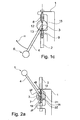
- a first embodiment of a toggle press is shown.
- the in the Fig. 1a - 1c simplified illustrated sections of a hand-operated toggle press has a C-shaped stand 1, a press ram 2, which is guided vertically in the stand 1 and a pivotable about an axis 3 operating lever 4.
- the axis 3 is mounted on a pivotally mounted but in the Fig. 1a - 1c not visible pivot lever arranged (s. Fig. 3b ; Pivoting lever 24).
- the operating lever 4 is located in Fig. 1a in a top dead center position 5, whereas in FIG Fig. 1c this is shown in a bottom dead center 6.
- Tot Vietnamese collagen are defined by the fact that the press ram 2 can move between these two positions maximum.
- the mounting lever 4 has at its stator-side end a support member 7 in the form of a round disc, which is connected via a linear toggle lever 8 on the one hand to the stator 1 and another linear toggle lever 9 on the other hand with the press ram 2 articulated, preferably pivotally.
- the toggle lever 8 is pivotally connected at one end via a hinge 10 to the stator 1.
- the further end of the toggle lever 8 is pivotally coupled via an articulation point 12.
- the further knee lever 9 is advantageously arranged point-symmetrical to the axis 3. This results in that the toggle lever 9 is pivotally coupled at one end via a hinge 11 to the press ram 2 and with its other end pivotally connected via an articulation point 13 on the carrier element 7.
- the support member 7 has further articulation points for the free ends of the toggle lever 8, 9. These are visible due to the pivoting in the direction ⁇ .
- the other articulation points are identified by reference numerals 15 and 16.
- the positions of the hinge connection points 15; 16, which are arranged radially outward (direction R) from the axis 3 of the actuating lever 4 outwards at equal intervals, wherein the distances may also be unequal and the joint connection points 12; 13 and 15; 16 are only in number exemplary.
- the articulation points seen from their radial arrangement can also deviate therefrom.
- the in the Fig. 1 illustrated embodiment represents a toggle press, which is designed as a press-in press.
- Knob press shown is preferably to use as a press-out press. In press-in presses, the highest force is achieved on the last path towards the bottom dead center, in particular when the operating lever has exceeded the horizontal position when pressed down.
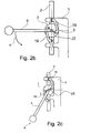
- toggle press is by in the Fig. 2a - 2c shown in simplified sections and generally coincides with the cutouts in the Fig. 1a - 1c , therefore, the same parts bear the same reference numerals.
- the toggle - designated 18 and 19 - executed bent, that is, they have the shape of a kind of drawer handle (seen in plan view).
- Fig. 2a - 2c The in the Fig. 2a - 2c simplified illustrated sections of a hand-operated toggle press has a C-shaped stand 1, a press ram 2, which is guided vertically in the stand 1 and a pivotable about an axis 3 operating lever 4.
- the axis 3 is connected to a pivoting lever not shown (for example, according to the Swivel lever 24 in Fig. 3b ), so that the carrier element 7 moves with the pivoting movement of the actuating lever 4 with.
- the operating lever 4 is located in Fig. 2a in a top dead center position 5, whereas in FIG Fig. 2c this is shown in a lower layer 6. These layers are defined by the fact that the press ram 2 can move maximally between these two positions.
- the mounting lever 4 has at its stator-side end the support member 7 in the form of a round disc, which is connected via the first toggle lever 18 on the one hand to the stator 1 and the other linear toggle lever 19 on the other hand with the press ram 2 articulated, preferably pivotally.
- the first toggle lever 18 is pivotally connected at one end via the hinge 10 to the stator 1.
- the further end of the toggle lever 18 is pivotally coupled to the carrier element 7 via a joint connection point 20.
- the further knee lever 19 is advantageously arranged point-symmetrical to the axis 3. As a result, it turns out that the Knee lever 19 with its one end about the joint 11 pivotally coupled to the press ram 2 and with its other end pivotally connected via an articulation point 21 to the support member 7. Due to the special design of the knee lever 18, 19 is in the in Fig. 2a shown position the greatest possible force can be applied.
- the support member 7 has further articulation points for the free end of the toggle 18, 19. These are due to the pivoting in the direction ⁇ only partially visible.
- the other articulation points are identified by the reference numerals 22 and 23, which are arranged radially from the axis 3 of the actuating lever 4 outwards at equal intervals, wherein the distances may also be unequal and are only exemplary of their number. Furthermore, the positions of these articulation points can also differ from their radial arrangement.
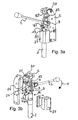
- a third embodiment of a toggle press is shown.
- explosively illustrated sections of a hand-operated toggle press has a C-shaped stand 1, a press ram 2, which is guided vertically in the stand 1 and one to a Axis 3 pivotable actuating lever 4.
- the operating lever 4 is located in Fig. 3a and 3b in any position.
- the actuating lever 4 has at its stator-side end a support element 7.1 in the form of a lever and is rotatably connected thereto.
- the support member 7.1 is formed like a double lever and includes at its two ends a toggle 8.1 and at its other end a toggle 9.1, which are pivotally connected to each other via the support member 7.1.
- the toggle 8.1 is connected at one end fixed but pivotally connected to the C-shaped stand 1 via a hinge 10. The further end of the toggle lever 8.1 is coupled via a joint connection point 12 with the carrier element 7.1.
- the other toggle lever 9.1 is connected via a not shown in detail in the drawing joint (11) with the press ram 2, wherein the other end of the other knee lever 9.1 is pivotally coupled via a hinge connection point 13 with the support member 7.1.
- the axis 3 of the actuating lever 4, as in particular in Fig. 3b can be seen, is hinged to a pivot lever 24 which is pivotally mounted on the stator 1 via a rotation axis 25.
- a spring 26 is provided which presses the actuating lever 4 in a corresponding initial position, wherein upon actuation of the actuating lever 4 in the direction of arrow ⁇ , the spring force must be overcome.
- the press ram 2 itself is guided into a guide element 27, which essentially forms the toggle lever press with the remaining part of the C-shaped upright 1. Due to the arrangement of the support member 7.1 and the associated toggle levers 8.1 and 9.1, it is possible to increase the stroke length of the press ram 2 due to a movement of the operating lever 4 in the direction ⁇ considerably.
- the greater force is generated when the operating lever 4 has reached a position in which the pivot points 12 and 13 are arranged axially in the direction of the press ram 2.
- toggle press it is advantageously possible to change the respective stroke length or the respective stroke and thereby also the flow of forces for the press ram 2 in a simple manner to thereby adapt the toggle press to the respective requirements of a production can, as the applied forces and the creation of working space.
Landscapes
- Engineering & Computer Science (AREA)
- Mechanical Engineering (AREA)
- Press Drives And Press Lines (AREA)
Priority Applications (1)
| Application Number | Priority Date | Filing Date | Title |
|---|---|---|---|
| PL11727796T PL2576196T3 (pl) | 2010-05-31 | 2011-05-31 | Ręcznie obsługiwana prasa z dźwignią kolanową z dużym skokiem |
Applications Claiming Priority (2)
| Application Number | Priority Date | Filing Date | Title |
|---|---|---|---|
| DE102010017157A DE102010017157A1 (de) | 2010-05-31 | 2010-05-31 | Handbetätigbare Kniehebelpresse mit einstellbarem Arbeitshub |
| PCT/IB2011/052397 WO2011151790A2 (de) | 2010-05-31 | 2011-05-31 | Handbetätigbare kniehebelpresse mit grossem arbeitshub |
Publications (2)
| Publication Number | Publication Date |
|---|---|
| EP2576196A2 EP2576196A2 (de) | 2013-04-10 |
| EP2576196B1 true EP2576196B1 (de) | 2014-04-30 |
Family
ID=44627480
Family Applications (1)
| Application Number | Title | Priority Date | Filing Date |
|---|---|---|---|
| EP11727796.2A Not-in-force EP2576196B1 (de) | 2010-05-31 | 2011-05-31 | Handbetätigbare kniehebelpresse mit grossem arbeitshub |
Country Status (5)
| Country | Link |
|---|---|
| EP (1) | EP2576196B1 (pl) |
| CN (1) | CN203427337U (pl) |
| DE (1) | DE102010017157A1 (pl) |
| PL (1) | PL2576196T3 (pl) |
| WO (1) | WO2011151790A2 (pl) |
Families Citing this family (2)
| Publication number | Priority date | Publication date | Assignee | Title |
|---|---|---|---|---|
| CN103991600A (zh) * | 2014-04-29 | 2014-08-20 | 成都联创精密机械有限公司 | 一种捆扎充气式减震器的手动压缩器 |
| CN114343979A (zh) * | 2016-02-03 | 2022-04-15 | 宝洁公司 | 具有弹性带的可穿着制品 |
Family Cites Families (10)
| Publication number | Priority date | Publication date | Assignee | Title |
|---|---|---|---|---|
| US609606A (en) * | 1898-08-23 | Copying-press | ||
| US1007923A (en) * | 1910-04-02 | 1911-11-07 | New York Die Company | Embossing-press. |
| GB326542A (en) * | 1928-12-15 | 1930-03-17 | Frederick Donald Lingwood | Improvements in or relating to link mechanisms |
| GB587363A (en) * | 1944-08-18 | 1947-04-23 | Percival James Packman | Improvements in or relating to toggle presses |
| DE1679923A1 (de) * | 1967-04-04 | 1971-05-19 | Buchmann Rudolf Ch | Maschine mit Mittelantrieb fuer gegenueberliegende Formbewegungs- und Schliessvorrichtungen mit oder ohne Formeneinbauhoehenverstellung |
| GB1309763A (en) * | 1970-03-16 | 1973-03-14 | Erlenbach H | Moulding machine |
| US5147496A (en) * | 1991-03-06 | 1992-09-15 | Hix Corporation | Linkage for heat transfer machine |
| JPH04367396A (ja) * | 1991-06-13 | 1992-12-18 | Japan Aviation Electron Ind Ltd | 手動プレス |
| DE102004026450B4 (de) * | 2004-05-29 | 2007-10-25 | Krauss Maffei Gmbh | Schließeinheit mit Doppelkurbelantrieb |
| DE102005025756A1 (de) * | 2004-06-22 | 2006-01-19 | Tox Pressotechnik Gmbh & Co. Kg | Presse, Führung für ein Führungselement einer Presse |
-
2010
- 2010-05-31 DE DE102010017157A patent/DE102010017157A1/de not_active Withdrawn
-
2011
- 2011-05-31 EP EP11727796.2A patent/EP2576196B1/de not_active Not-in-force
- 2011-05-31 PL PL11727796T patent/PL2576196T3/pl unknown
- 2011-05-31 WO PCT/IB2011/052397 patent/WO2011151790A2/de not_active Ceased
- 2011-05-31 CN CN201190000633.2U patent/CN203427337U/zh not_active Expired - Lifetime
Also Published As
| Publication number | Publication date |
|---|---|
| CN203427337U (zh) | 2014-02-12 |
| PL2576196T3 (pl) | 2014-11-28 |
| DE102010017157A1 (de) | 2011-12-01 |
| WO2011151790A2 (de) | 2011-12-08 |
| EP2576196A2 (de) | 2013-04-10 |
| WO2011151790A3 (de) | 2012-01-26 |
Similar Documents
| Publication | Publication Date | Title |
|---|---|---|
| EP2486908B1 (de) | Operationstischsäule | |
| DE1725004B1 (de) | Bremsbackenfuehrung fuer eine hydraulisch betaetigbare Teilbelagscheibenbremse | |
| DE2031511C3 (de) | Mechanische Betätigungsvorrichtung für Fahrzeuginnenbackenbremsen | |
| DE2812086C3 (de) | Vorrichtung zum Befestigen eines Metallklemmbandes um einen mit einer Hülse versehenen zylindrischen Körper | |
| EP2576196B1 (de) | Handbetätigbare kniehebelpresse mit grossem arbeitshub | |
| DE2357860C2 (de) | Kupplung | |
| DE2328182C2 (de) | Antrieb für eine mechanische Presse | |
| DE3232475C2 (pl) | ||
| DE69300891T2 (de) | Hochleistungs-Bördelmaschine zum Verschliessen von Konservendosen. | |
| DE2232709A1 (de) | Betaetigungs- oder kraftverstaerkungseinrichtung | |
| EP2007265B1 (de) | Klappbare wischerplatte | |
| DE2755986C2 (de) | Wippwerk für einen Kran | |
| EP0582778B1 (de) | Einrichtung zum Zusammendrücken von Dosen | |
| DD202274A5 (de) | Schienenzange | |
| DE1752698C3 (de) | Vorrichtung für den Längsvorschub eines schlanken, gegen Ausknicken zu sichernden Druckerzeugungsstempels für das hydrostatische Strangpressen o.dgl. Maschinenelementes bzw. Werkstückes | |
| CH644275A5 (de) | Skibremse. | |
| DE202020101214U1 (de) | Tisch mit einer Tischplatte und einem Tischplattenergänzungsteil | |
| CH696158A5 (de) | Schwenkbiegemaschine. | |
| DE2910874C2 (de) | Einlegegerät | |
| DE10330303B4 (de) | Falzzylinder zur Bearbeitung von Druckerzeugnissen | |
| DE102005056825A1 (de) | Möbelstück mit einer Plattenanordnung | |
| DE2910835C2 (de) | Wechseltisch | |
| DE2758861B1 (de) | Mast mit umlegbarem oberen Mastteil | |
| EP4640374A1 (de) | Spannvorrichtung | |
| DE2920776C2 (pl) |
Legal Events
| Date | Code | Title | Description |
|---|---|---|---|
| PUAI | Public reference made under article 153(3) epc to a published international application that has entered the european phase |
Free format text: ORIGINAL CODE: 0009012 |
|
| 17P | Request for examination filed |
Effective date: 20121221 |
|
| AK | Designated contracting states |
Kind code of ref document: A2 Designated state(s): AL AT BE BG CH CY CZ DE DK EE ES FI FR GB GR HR HU IE IS IT LI LT LU LV MC MK MT NL NO PL PT RO RS SE SI SK SM TR |
|
| DAX | Request for extension of the european patent (deleted) | ||
| REG | Reference to a national code |
Ref country code: DE Ref legal event code: R079 Ref document number: 502011002929 Country of ref document: DE Free format text: PREVIOUS MAIN CLASS: B30B0001120000 Ipc: B30B0001140000 |
|
| GRAP | Despatch of communication of intention to grant a patent |
Free format text: ORIGINAL CODE: EPIDOSNIGR1 |
|
| RIC1 | Information provided on ipc code assigned before grant |
Ipc: B30B 1/14 20060101AFI20131004BHEP Ipc: B30B 1/12 20060101ALI20131004BHEP |
|
| INTG | Intention to grant announced |
Effective date: 20131113 |
|
| GRAS | Grant fee paid |
Free format text: ORIGINAL CODE: EPIDOSNIGR3 |
|
| GRAA | (expected) grant |
Free format text: ORIGINAL CODE: 0009210 |
|
| AK | Designated contracting states |
Kind code of ref document: B1 Designated state(s): AL AT BE BG CH CY CZ DE DK EE ES FI FR GB GR HR HU IE IS IT LI LT LU LV MC MK MT NL NO PL PT RO RS SE SI SK SM TR |
|
| REG | Reference to a national code |
Ref country code: GB Ref legal event code: FG4D Free format text: NOT ENGLISH Ref country code: CH Ref legal event code: EP |
|
| REG | Reference to a national code |
Ref country code: AT Ref legal event code: REF Ref document number: 664805 Country of ref document: AT Kind code of ref document: T Effective date: 20140515 |
|
| REG | Reference to a national code |
Ref country code: IE Ref legal event code: FG4D Free format text: LANGUAGE OF EP DOCUMENT: GERMAN |
|
| REG | Reference to a national code |
Ref country code: DE Ref legal event code: R096 Ref document number: 502011002929 Country of ref document: DE Effective date: 20140612 |
|
| REG | Reference to a national code |
Ref country code: LT Ref legal event code: MG4D |
|
| REG | Reference to a national code |
Ref country code: NL Ref legal event code: VDEP Effective date: 20140430 |
|
| REG | Reference to a national code |
Ref country code: CH Ref legal event code: NV Representative=s name: PATENTANWALT DIPL.-ING. (UNI.) WOLFGANG HEISEL, CH |
|
| PG25 | Lapsed in a contracting state [announced via postgrant information from national office to epo] |
Ref country code: GR Free format text: LAPSE BECAUSE OF FAILURE TO SUBMIT A TRANSLATION OF THE DESCRIPTION OR TO PAY THE FEE WITHIN THE PRESCRIBED TIME-LIMIT Effective date: 20140731 Ref country code: LT Free format text: LAPSE BECAUSE OF FAILURE TO SUBMIT A TRANSLATION OF THE DESCRIPTION OR TO PAY THE FEE WITHIN THE PRESCRIBED TIME-LIMIT Effective date: 20140430 Ref country code: FI Free format text: LAPSE BECAUSE OF FAILURE TO SUBMIT A TRANSLATION OF THE DESCRIPTION OR TO PAY THE FEE WITHIN THE PRESCRIBED TIME-LIMIT Effective date: 20140430 Ref country code: CY Free format text: LAPSE BECAUSE OF FAILURE TO SUBMIT A TRANSLATION OF THE DESCRIPTION OR TO PAY THE FEE WITHIN THE PRESCRIBED TIME-LIMIT Effective date: 20140430 Ref country code: NO Free format text: LAPSE BECAUSE OF FAILURE TO SUBMIT A TRANSLATION OF THE DESCRIPTION OR TO PAY THE FEE WITHIN THE PRESCRIBED TIME-LIMIT Effective date: 20140730 Ref country code: BG Free format text: LAPSE BECAUSE OF FAILURE TO SUBMIT A TRANSLATION OF THE DESCRIPTION OR TO PAY THE FEE WITHIN THE PRESCRIBED TIME-LIMIT Effective date: 20140730 Ref country code: IS Free format text: LAPSE BECAUSE OF FAILURE TO SUBMIT A TRANSLATION OF THE DESCRIPTION OR TO PAY THE FEE WITHIN THE PRESCRIBED TIME-LIMIT Effective date: 20140830 Ref country code: NL Free format text: LAPSE BECAUSE OF FAILURE TO SUBMIT A TRANSLATION OF THE DESCRIPTION OR TO PAY THE FEE WITHIN THE PRESCRIBED TIME-LIMIT Effective date: 20140430 |
|
| PG25 | Lapsed in a contracting state [announced via postgrant information from national office to epo] |
Ref country code: HR Free format text: LAPSE BECAUSE OF FAILURE TO SUBMIT A TRANSLATION OF THE DESCRIPTION OR TO PAY THE FEE WITHIN THE PRESCRIBED TIME-LIMIT Effective date: 20140430 Ref country code: ES Free format text: LAPSE BECAUSE OF FAILURE TO SUBMIT A TRANSLATION OF THE DESCRIPTION OR TO PAY THE FEE WITHIN THE PRESCRIBED TIME-LIMIT Effective date: 20140430 Ref country code: RS Free format text: LAPSE BECAUSE OF FAILURE TO SUBMIT A TRANSLATION OF THE DESCRIPTION OR TO PAY THE FEE WITHIN THE PRESCRIBED TIME-LIMIT Effective date: 20140430 Ref country code: LV Free format text: LAPSE BECAUSE OF FAILURE TO SUBMIT A TRANSLATION OF THE DESCRIPTION OR TO PAY THE FEE WITHIN THE PRESCRIBED TIME-LIMIT Effective date: 20140430 Ref country code: SE Free format text: LAPSE BECAUSE OF FAILURE TO SUBMIT A TRANSLATION OF THE DESCRIPTION OR TO PAY THE FEE WITHIN THE PRESCRIBED TIME-LIMIT Effective date: 20140430 |
|
| REG | Reference to a national code |
Ref country code: PL Ref legal event code: T3 |
|
| PG25 | Lapsed in a contracting state [announced via postgrant information from national office to epo] |
Ref country code: PT Free format text: LAPSE BECAUSE OF FAILURE TO SUBMIT A TRANSLATION OF THE DESCRIPTION OR TO PAY THE FEE WITHIN THE PRESCRIBED TIME-LIMIT Effective date: 20140901 |
|
| PG25 | Lapsed in a contracting state [announced via postgrant information from national office to epo] |
Ref country code: RO Free format text: LAPSE BECAUSE OF FAILURE TO SUBMIT A TRANSLATION OF THE DESCRIPTION OR TO PAY THE FEE WITHIN THE PRESCRIBED TIME-LIMIT Effective date: 20140430 Ref country code: CZ Free format text: LAPSE BECAUSE OF FAILURE TO SUBMIT A TRANSLATION OF THE DESCRIPTION OR TO PAY THE FEE WITHIN THE PRESCRIBED TIME-LIMIT Effective date: 20140430 Ref country code: MC Free format text: LAPSE BECAUSE OF FAILURE TO SUBMIT A TRANSLATION OF THE DESCRIPTION OR TO PAY THE FEE WITHIN THE PRESCRIBED TIME-LIMIT Effective date: 20140430 Ref country code: SK Free format text: LAPSE BECAUSE OF FAILURE TO SUBMIT A TRANSLATION OF THE DESCRIPTION OR TO PAY THE FEE WITHIN THE PRESCRIBED TIME-LIMIT Effective date: 20140430 Ref country code: EE Free format text: LAPSE BECAUSE OF FAILURE TO SUBMIT A TRANSLATION OF THE DESCRIPTION OR TO PAY THE FEE WITHIN THE PRESCRIBED TIME-LIMIT Effective date: 20140430 Ref country code: DK Free format text: LAPSE BECAUSE OF FAILURE TO SUBMIT A TRANSLATION OF THE DESCRIPTION OR TO PAY THE FEE WITHIN THE PRESCRIBED TIME-LIMIT Effective date: 20140430 |
|
| REG | Reference to a national code |
Ref country code: DE Ref legal event code: R097 Ref document number: 502011002929 Country of ref document: DE |
|
| REG | Reference to a national code |
Ref country code: IE Ref legal event code: MM4A |
|
| PLBE | No opposition filed within time limit |
Free format text: ORIGINAL CODE: 0009261 |
|
| STAA | Information on the status of an ep patent application or granted ep patent |
Free format text: STATUS: NO OPPOSITION FILED WITHIN TIME LIMIT |
|
| PG25 | Lapsed in a contracting state [announced via postgrant information from national office to epo] |
Ref country code: IT Free format text: LAPSE BECAUSE OF FAILURE TO SUBMIT A TRANSLATION OF THE DESCRIPTION OR TO PAY THE FEE WITHIN THE PRESCRIBED TIME-LIMIT Effective date: 20140430 |
|
| 26N | No opposition filed |
Effective date: 20150202 |
|
| PG25 | Lapsed in a contracting state [announced via postgrant information from national office to epo] |
Ref country code: IE Free format text: LAPSE BECAUSE OF NON-PAYMENT OF DUE FEES Effective date: 20140531 |
|
| REG | Reference to a national code |
Ref country code: DE Ref legal event code: R097 Ref document number: 502011002929 Country of ref document: DE Effective date: 20150202 |
|
| PG25 | Lapsed in a contracting state [announced via postgrant information from national office to epo] |
Ref country code: SI Free format text: LAPSE BECAUSE OF FAILURE TO SUBMIT A TRANSLATION OF THE DESCRIPTION OR TO PAY THE FEE WITHIN THE PRESCRIBED TIME-LIMIT Effective date: 20140430 |
|
| PG25 | Lapsed in a contracting state [announced via postgrant information from national office to epo] |
Ref country code: MT Free format text: LAPSE BECAUSE OF FAILURE TO SUBMIT A TRANSLATION OF THE DESCRIPTION OR TO PAY THE FEE WITHIN THE PRESCRIBED TIME-LIMIT Effective date: 20140430 |
|
| PG25 | Lapsed in a contracting state [announced via postgrant information from national office to epo] |
Ref country code: SM Free format text: LAPSE BECAUSE OF FAILURE TO SUBMIT A TRANSLATION OF THE DESCRIPTION OR TO PAY THE FEE WITHIN THE PRESCRIBED TIME-LIMIT Effective date: 20140430 |
|
| REG | Reference to a national code |
Ref country code: FR Ref legal event code: PLFP Year of fee payment: 6 |
|
| PG25 | Lapsed in a contracting state [announced via postgrant information from national office to epo] |
Ref country code: LU Free format text: LAPSE BECAUSE OF NON-PAYMENT OF DUE FEES Effective date: 20140531 Ref country code: BE Free format text: LAPSE BECAUSE OF FAILURE TO SUBMIT A TRANSLATION OF THE DESCRIPTION OR TO PAY THE FEE WITHIN THE PRESCRIBED TIME-LIMIT Effective date: 20140531 Ref country code: HU Free format text: LAPSE BECAUSE OF FAILURE TO SUBMIT A TRANSLATION OF THE DESCRIPTION OR TO PAY THE FEE WITHIN THE PRESCRIBED TIME-LIMIT; INVALID AB INITIO Effective date: 20110531 Ref country code: TR Free format text: LAPSE BECAUSE OF FAILURE TO SUBMIT A TRANSLATION OF THE DESCRIPTION OR TO PAY THE FEE WITHIN THE PRESCRIBED TIME-LIMIT Effective date: 20140430 |
|
| REG | Reference to a national code |
Ref country code: FR Ref legal event code: PLFP Year of fee payment: 7 |
|
| REG | Reference to a national code |
Ref country code: FR Ref legal event code: PLFP Year of fee payment: 8 |
|
| PG25 | Lapsed in a contracting state [announced via postgrant information from national office to epo] |
Ref country code: MK Free format text: LAPSE BECAUSE OF FAILURE TO SUBMIT A TRANSLATION OF THE DESCRIPTION OR TO PAY THE FEE WITHIN THE PRESCRIBED TIME-LIMIT Effective date: 20140430 |
|
| PG25 | Lapsed in a contracting state [announced via postgrant information from national office to epo] |
Ref country code: AL Free format text: LAPSE BECAUSE OF FAILURE TO SUBMIT A TRANSLATION OF THE DESCRIPTION OR TO PAY THE FEE WITHIN THE PRESCRIBED TIME-LIMIT Effective date: 20140430 |
|
| PGFP | Annual fee paid to national office [announced via postgrant information from national office to epo] |
Ref country code: CH Payment date: 20200525 Year of fee payment: 10 Ref country code: DE Payment date: 20200519 Year of fee payment: 10 Ref country code: FR Payment date: 20200519 Year of fee payment: 10 |
|
| PGFP | Annual fee paid to national office [announced via postgrant information from national office to epo] |
Ref country code: GB Payment date: 20200522 Year of fee payment: 10 Ref country code: PL Payment date: 20200520 Year of fee payment: 10 |
|
| PGFP | Annual fee paid to national office [announced via postgrant information from national office to epo] |
Ref country code: AT Payment date: 20200519 Year of fee payment: 10 |
|
| REG | Reference to a national code |
Ref country code: DE Ref legal event code: R119 Ref document number: 502011002929 Country of ref document: DE |
|
| REG | Reference to a national code |
Ref country code: CH Ref legal event code: PL |
|
| REG | Reference to a national code |
Ref country code: AT Ref legal event code: MM01 Ref document number: 664805 Country of ref document: AT Kind code of ref document: T Effective date: 20210531 |
|
| GBPC | Gb: european patent ceased through non-payment of renewal fee |
Effective date: 20210531 |
|
| PG25 | Lapsed in a contracting state [announced via postgrant information from national office to epo] |
Ref country code: LI Free format text: LAPSE BECAUSE OF NON-PAYMENT OF DUE FEES Effective date: 20210531 Ref country code: AT Free format text: LAPSE BECAUSE OF NON-PAYMENT OF DUE FEES Effective date: 20210531 Ref country code: CH Free format text: LAPSE BECAUSE OF NON-PAYMENT OF DUE FEES Effective date: 20210531 |
|
| PG25 | Lapsed in a contracting state [announced via postgrant information from national office to epo] |
Ref country code: GB Free format text: LAPSE BECAUSE OF NON-PAYMENT OF DUE FEES Effective date: 20210531 Ref country code: DE Free format text: LAPSE BECAUSE OF NON-PAYMENT OF DUE FEES Effective date: 20211201 |
|
| PG25 | Lapsed in a contracting state [announced via postgrant information from national office to epo] |
Ref country code: FR Free format text: LAPSE BECAUSE OF NON-PAYMENT OF DUE FEES Effective date: 20210531 |
|
| PG25 | Lapsed in a contracting state [announced via postgrant information from national office to epo] |
Ref country code: PL Free format text: LAPSE BECAUSE OF NON-PAYMENT OF DUE FEES Effective date: 20210531 |