EP2576247B1 - Suspension de roue individuelle pour une roue directrice à suspension - Google Patents
Suspension de roue individuelle pour une roue directrice à suspension Download PDFInfo
- Publication number
- EP2576247B1 EP2576247B1 EP11723046.6A EP11723046A EP2576247B1 EP 2576247 B1 EP2576247 B1 EP 2576247B1 EP 11723046 A EP11723046 A EP 11723046A EP 2576247 B1 EP2576247 B1 EP 2576247B1
- Authority
- EP
- European Patent Office
- Prior art keywords
- steering column
- wheel suspension
- independent wheel
- independent
- fork bridge
- Prior art date
- Legal status (The legal status is an assumption and is not a legal conclusion. Google has not performed a legal analysis and makes no representation as to the accuracy of the status listed.)
- Not-in-force
Links
- 239000000725 suspension Substances 0.000 title claims description 69
- 238000013016 damping Methods 0.000 claims description 39
- 239000012530 fluid Substances 0.000 claims 1
- 238000003971 tillage Methods 0.000 description 4
- 239000007921 spray Substances 0.000 description 3
- 230000008878 coupling Effects 0.000 description 2
- 238000010168 coupling process Methods 0.000 description 2
- 238000005859 coupling reaction Methods 0.000 description 2
- 230000002706 hydrostatic effect Effects 0.000 description 2
- 238000009434 installation Methods 0.000 description 2
- 239000002689 soil Substances 0.000 description 2
- 230000009286 beneficial effect Effects 0.000 description 1
- 230000005540 biological transmission Effects 0.000 description 1
- 230000006835 compression Effects 0.000 description 1
- 238000007906 compression Methods 0.000 description 1
- 230000001419 dependent effect Effects 0.000 description 1
- 238000011161 development Methods 0.000 description 1
- 230000018109 developmental process Effects 0.000 description 1
- 230000002349 favourable effect Effects 0.000 description 1
- 230000001771 impaired effect Effects 0.000 description 1
- 230000010354 integration Effects 0.000 description 1
- 239000000463 material Substances 0.000 description 1
- 238000012986 modification Methods 0.000 description 1
- 230000004048 modification Effects 0.000 description 1
- 238000005457 optimization Methods 0.000 description 1
- 230000003716 rejuvenation Effects 0.000 description 1
Images


Classifications
-
- B—PERFORMING OPERATIONS; TRANSPORTING
- B60—VEHICLES IN GENERAL
- B60G—VEHICLE SUSPENSION ARRANGEMENTS
- B60G3/00—Resilient suspensions for a single wheel
- B60G3/01—Resilient suspensions for a single wheel the wheel being mounted for sliding movement, e.g. in or on a vertical guide
-
- B—PERFORMING OPERATIONS; TRANSPORTING
- B60—VEHICLES IN GENERAL
- B60G—VEHICLE SUSPENSION ARRANGEMENTS
- B60G11/00—Resilient suspensions characterised by arrangement, location or kind of springs
- B60G11/26—Resilient suspensions characterised by arrangement, location or kind of springs having fluid springs only, e.g. hydropneumatic springs
- B60G11/30—Resilient suspensions characterised by arrangement, location or kind of springs having fluid springs only, e.g. hydropneumatic springs having pressure fluid accumulator therefor, e.g. accumulator arranged in vehicle frame
-
- B—PERFORMING OPERATIONS; TRANSPORTING
- B62—LAND VEHICLES FOR TRAVELLING OTHERWISE THAN ON RAILS
- B62D—MOTOR VEHICLES; TRAILERS
- B62D7/00—Steering linkage; Stub axles or their mountings
- B62D7/06—Steering linkage; Stub axles or their mountings for individually-pivoted wheels, e.g. on king-pins
-
- B—PERFORMING OPERATIONS; TRANSPORTING
- B60—VEHICLES IN GENERAL
- B60G—VEHICLE SUSPENSION ARRANGEMENTS
- B60G2200/00—Indexing codes relating to suspension types
- B60G2200/10—Independent suspensions
-
- B—PERFORMING OPERATIONS; TRANSPORTING
- B60—VEHICLES IN GENERAL
- B60G—VEHICLE SUSPENSION ARRANGEMENTS
- B60G2200/00—Indexing codes relating to suspension types
- B60G2200/40—Indexing codes relating to the wheels in the suspensions
- B60G2200/44—Indexing codes relating to the wheels in the suspensions steerable
-
- B—PERFORMING OPERATIONS; TRANSPORTING
- B60—VEHICLES IN GENERAL
- B60G—VEHICLE SUSPENSION ARRANGEMENTS
- B60G2202/00—Indexing codes relating to the type of spring, damper or actuator
- B60G2202/10—Type of spring
- B60G2202/15—Fluid spring
- B60G2202/154—Fluid spring with an accumulator
-
- B—PERFORMING OPERATIONS; TRANSPORTING
- B60—VEHICLES IN GENERAL
- B60G—VEHICLE SUSPENSION ARRANGEMENTS
- B60G2204/00—Indexing codes related to suspensions per se or to auxiliary parts
- B60G2204/40—Auxiliary suspension parts; Adjustment of suspensions
- B60G2204/423—Rails, tubes, or the like, for guiding the movement of suspension elements
- B60G2204/4232—Sliding mounts
-
- B—PERFORMING OPERATIONS; TRANSPORTING
- B60—VEHICLES IN GENERAL
- B60G—VEHICLE SUSPENSION ARRANGEMENTS
- B60G2300/00—Indexing codes relating to the type of vehicle
- B60G2300/08—Agricultural vehicles
-
- B—PERFORMING OPERATIONS; TRANSPORTING
- B60—VEHICLES IN GENERAL
- B60Y—INDEXING SCHEME RELATING TO ASPECTS CROSS-CUTTING VEHICLE TECHNOLOGY
- B60Y2200/00—Type of vehicle
- B60Y2200/20—Off-Road Vehicles
- B60Y2200/22—Agricultural vehicles
Definitions
- the present invention relates to an independent wheel suspension for a steerable wheel of a vehicle having the features of independent claim 1.
- the DE 8404619 U1 discloses such independent suspension, in which a wheel is resiliently mounted via a swing arm, which is arranged on a hydraulic cylinder, so that a linear movement of the wheel is converted into a moment. Additional resources are required for this, which can result in additional costs and increased space requirements. Further, no steering of the wheel and no drive of the wheel can take place.
- an axle suspension of an agricultural vehicle in which a steerable wheel is equipped with an air suspension. In this way, a suspension is created, are sprung and / or damped in the vertical spring movements of a steering axle via an air spring bellows.
- the EP 1 685 988 B describes a suspension system for an agricultural vehicle having steerable independent suspensions.
- a motor housing of a wheel hub motor o. The like.
- An upper end of the support tube rotatable for the purpose of steering is coupled with an air spring bellows, so that the entire suspension is provided a limited spring travel.
- a primary object of the invention is to provide an improved independent suspension of a steered and / or driven wheel with spring system available.
- This independent suspension should be as stable as possible, provide large spring travel available, be coupled with a simply functioning damping coupled as compact as possible.
- the present invention proposes an independent wheel suspension for a steerable wheel of a vehicle, in particular an agricultural train, transport or special vehicle, in which a steering column interacts via a fork bridge with a linear guide which is movable in an approximately vertical direction.
- the fork bridge produces a pivotable about an approximately vertical axis of rotation steering connection to a vehicle frame.
- the linear guide is coupled to a fluidic spring and / or damping element, which forms a supporting part of the fork bridge.
- the fluidic spring and / or damping element can extend into the steering column or be integrated there.
- the fluidic spring and / or damping element can be arranged as an integrated component in the steering column, wherein the steering column, for example, can be designed as a cylinder or lifting cylinder for the fluidic spring and / or damping element.
- a preferred variant of the independent wheel suspension according to the invention can also provide that the linear guide is provided with a drive motor for driving the steerable wheel.
- a drive motor for driving the steerable wheel.
- either the two wheels of an axle with hydrostatic or electric wheel hub motors o.
- All the wheels of a vehicle may be provided with such drive motors on the suspensions.
- the particularly compact design and the realizable long spring travel can help ensure that a very large ground clearance of the vehicle can be realized, which, for example, can be very beneficial for care work with a relatively high crop population or for use in special crops.
- the steerability of the axles may, for example, be realized by appropriate steering levers which selectively engage the steering column of each suspension or on other suspension parts.
- the required steering forces can be done by Hebelanlenkitch above the stub axle or in a conventional manner via a linkage on the stub axles themselves.
- the steering column itself be designed to transmit a torque to the fork bridge.
- the linear guide can be formed, for example, by a slide or the like, with the carriage and the fork bridge coupled to the steering column each having at least one linear guide element through which at least one guide rod extends, so that the carriage and the fork bridge move relative to each other linear direction to each other are movable.
- This suspension provides the necessary stability, since the slide guide can be designed so that the guide rods or the at least one guide rod is covered over a sufficient length, whereby favorable leverage conditions arise. So can the steering column For example, on its underside in a fork bridge o. The like.
- An alternative embodiment of the independent suspension according to the invention may provide that the cylinder or the spring and / or damping element which is coupled to the steering column or there at least partially integrated, having a bellows, which is resiliently connected to a punch of the carriage.
- This bellows can be arranged, for example, as an additional spring element between a fork bridge or a lower stop element of the steering column and a supporting element of the sliding carriage and optionally as a resilient element and / or as a stop buffer to limit the maximum compression travel o.
- the spring and / or damping element can have one or more pressure reservoirs with connections, wherein the pressure reservoirs are preferably fluidically connected via line systems to the cylinder or the spring and / or damping element of the steering column. Due to the compact design of the entire suspension these pressure reservoirs or the at least one pressure reservoir, for example, be designed as small tanks, which are anchored together with the wheel hub motor on the slide and find space in this way in the wheel of the vehicle wheel hub motor anchored place without thereby the ground clearance or the clearance between the axles is affected or impaired in any way.
- the invention comprises an agricultural utility vehicle with at least one independent suspension according to one of the embodiments described above, a vehicle frame on which the at least one, but typically at least two independent suspensions are arranged.
- the agricultural utility vehicle may, for example, be designed as a towing vehicle and have at least one or more tillage devices fastened to the vehicle frame.
- the commercial vehicle may, however, also be used as a towing vehicle Multipurpose or combination vehicle or be designed as a special vehicle and have a semi-mounted device o. The like. With a spray tank or other agricultural functional components.
- the independent suspension according to the invention serves the sprung and / or damped wheel guide for a steerable wheel.
- the independent suspension can be provided, for example, for single- or multi-lane commercial vehicles. If several independent wheel suspensions claimed according to the invention are provided for a commercial vehicle, the rotational movement of one or more independent wheel suspensions can take place simultaneously or successively and homogeneously or inhomogeneously with respect to the rotational movement.
- a motor may be provided for driving the wheel.
- the motor can be arranged on the linear guide and drive the steerable wheel.
- the expert has a wide range available so that he can choose the power optimized in terms of the intended use of the claimed independent suspension.
- the engine can be designed, for example, as a wheel hub motor, as a gearbox with an oil motor or as an electric drive unit.
- the motor is connected via a movable in approximately vertical direction linear guide with a fork bridge.
- the linear guide can be configured for example via a rail guide.
- the pivotal connection may, depending on the selected embodiment, also include at least one ball bearing or similar components.
- the fork bridge produces a pivotable about a vertical axis of rotation 'steering connection to a vehicle frame.
- the linear guide is coupled to a fluidic spring and / or damping element.
- the fluidic spring and / or damping element can be, for example, a hydraulic and / or pneumatic spring system.
- the spring and / or damping element forms a supporting component of the fork bridge.
- the fork bridge may have one or more components of the spring and / or damping element.
- a steering column arranged on the fork bridge, be present.
- the steering column may be such that it also acts as a cylinder of a spring and / or damping element.
- the motor may be arranged on a carriage.
- the motor may be arranged on the carriage via screw and / or clamping connections and / or further additional fixing elements.
- the carriage may have a linear guide element through which a guide rod extends.
- the linear guide element may be formed, for example, as a bore or as a guide channel.
- the selected diameter of the guide element of the fork bridge may differ from the selected diameter of the guide element of the carriage.
- the selected diameter of the guide element of the fork bridge can be chosen such that it is designed as a press fit for the guide rod, so that the guide rod is fixedly arranged in the guide element of the fork bridge.
- the carriage and the yoke can be relatively movable in a linear direction to each other.
- the relative movement is such that the fork bridge assumes a fixed position and a linear movement of the carriage takes place to or away from the fork bridge.
- the cylinder has a bellows which is resiliently connected to a plunger of the carriage.
- the bellows is preferably formed of flexible material.
- the stamp can be formed for example by a flat surface on which the bellows can rest.
- the damping elements can have one or more pressure reservoirs with connections.
- the pressure reservoirs can be fluidically connected to the cylinder via line systems.
- the pressure reservoirs may be formed in a selected embodiment as a pneumatic and / or hydraulic cylinder.
- An inventively claimed independent suspension is known to be useful, for example, for agricultural utility vehicles, as here different bumps occur that can be sprung or dampened over design by means of the claimed Einzelradfederung.
- a tillage device may be attached to an agricultural utility vehicle, wherein the independent suspension Such is that it can carry the extra load without damage and the damping or suspension remains guaranteed even with additional load.
- the tillage device may be, for example, a spray boom.
- other tillage devices such as plows or the like come into consideration.
- the schematic perspective views of Fig. 1 and the Fig. 2 show different views of a variant of an independent suspension 1 according to the invention, as for example.
- the independent suspension 1 comprises a wheel hub motor 3 as a drive, which has a Radan gleichflansch 4 for a driven wheel of the vehicle.
- a Radan gleichflansch 4 for a driven wheel of the vehicle.
- the wheel hub motor 3 is connected via a movable in approximately vertical direction A linear guide 5 with a fork bridge 7.
- the in the embodiment shown as connected to a bottom of a steering column 17 fork bridge 7 provides a pivotable about an at least approximately vertical axis of rotation B steering connection to a vehicle frame (not shown) ago.
- the steering connection to the vehicle frame can also be articulated on the linear guide 5.
- the trained as a vertically movable carriage linear guide 5 is coupled to a fluidic spring and / or damping element 9.
- the damping element 9 in this case comprises a damping cylinder.
- the damping cylinder is formed in the embodiment shown at the same time as a steering column 17 or integrated there and can cause a rotational movement of the fork bridge 7 by means of torque transfer.
- the damping element 9 may comprise a bellows 15, which is at least in surface contact with the linear guide 5, but may also be connected to this.
- the linear guide 5 is formed in the embodiment shown as a slide 5a.
- the damping element 9 can, as shown in the embodiment shown, comprise one or more pressure compensation reservoirs 11. By means of the connections 13, the pressure in the pressure compensation reservoir 11 can be changed and thus the spring action of the damping element 9 can be influenced.
- the wheel hub motor 3 is designed hydraulically or as a hydrostatic drive in the illustrated embodiment and therefore has hydraulic connections 19.
- the perspective view of Fig. 2 shows a second view of the independent suspension 1 according to Fig. 1 ,
- the wheel hub motor 3 is arranged on a carriage 5a.
- the guide element 25 of the fork bridge 7 is formed in the embodiment shown as a bore in which a guide rod 23 is fixed by means of interference fit. Further, the guide rod 23 passes through a guide member 27 of the linear guide 5 and is covered by this.
- the guide element 27 is in the present case designed as a guide channel.
- the linear guide 5, formed in the embodiment shown as a slide 5a, and the fork bridge 7 are thus movable in the linear direction relative to each other.
- the wheel hub motor 3 is fixed to the linear guide 5 or the slide 5a via a fastening element 21.
- the fixation can be done for example via screw and / or plug-in connections provided in recesses 29 (not shown, cf. Fig. 4 ) and / or thread of the linear guide 5 engage.
- the Fig. 3 shows a perspective view of the carriage 5a.
- This carriage 5a has guide elements 27, which are formed in the embodiment shown as hollow channels.
- a stamp 31 is the carriage 5a, as in Fig. 1 shown in surface contact with one or more of the components of the spring and / or damping element 9. As in the in Fig. 1 shown embodiment, this may be, for example, the bellows 15.
- the Fig. 4 shows a further perspective view of the carriage 5a.
- the carriage 5a has attachment surfaces 33 for a fastener 21 (not shown, see Fig. 2 ) on.
- the mounting surfaces 33 are provided with recesses 29, which may include, for example, threads for fixing the fastener 21 via screw.
- the carriage 5a may have a taper 43 in predefined areas.
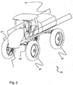
- FIG. 5 shows an embodiment of a commercial vehicle 35 with independent wheel suspensions 1.
- a wheel 37 is arranged on each of an independent suspension 1.
- the independent wheel suspensions are attached to a frame 39.
- a soil cultivation device in this case a spray boom 41 is further arranged on frame 39.
Landscapes
- Engineering & Computer Science (AREA)
- Mechanical Engineering (AREA)
- Chemical & Material Sciences (AREA)
- Combustion & Propulsion (AREA)
- Transportation (AREA)
- Vehicle Body Suspensions (AREA)
- Steering-Linkage Mechanisms And Four-Wheel Steering (AREA)
- Axle Suspensions And Sidecars For Cycles (AREA)
Claims (10)
- Suspension de roue individuelle (1) pour une roue (37) dirigeable d'un véhicule, en particulier d'un véhicule agricole tracteur, de transport ou spécial, comprenant une colonne de direction (17) qui, via un pont de fourche (7), agit de concert avec un guidage linéaire (5) déplaçable dans la direction (A) à peu près verticale, lequel pont de fourche (7) établit une liaison de direction à un châssis de véhicule (39), pivotante autour d'un axe de rotation (B) s'étendant à peu près verticalement, et lequel guidage linéaire (5) est couplé à un élément faisant ressort et/ou amortisseur (9) fluidique qui forme un composant porteur dudit pont de fourche (7), dans laquelle ledit guidage linéaire (5) est formé par un chariot (5a) et ladite colonne de direction (17) débouche, sur sa face inférieure, dans le pont de fourche (7), sur lequel pont de fourche (7) sont ancrées deux tiges de guidage (23) qui s'étendent jusqu'en bas parallèlement à la colonne de direction (17) et qui reçoivent le chariot (5a) déplaçable parallèlement à la colonne de direction (17) et le long des tiges de guidage (23) et guident celui-ci dans la direction longitudinale, ledit chariot (5a) recevant et portant un raccord de roue (4).
- Suspension de roue individuelle selon la revendication 1, dans laquelle au moins des parties de l'élément faisant ressort et/ou amortisseur (9) fluidique s'étendent jusque dans la colonne de direction (17) ou y sont intégrées.
- Suspension de roue individuelle selon la revendication 1 ou 2, dans laquelle ledit élément faisant ressort et/ou amortisseur (9) fluidique est disposé en tant que composant intégré dans la colonne de direction (17).
- Suspension de roue individuelle selon l'une quelconque des revendications 1 à 3, dans laquelle la colonne de direction (17) est réalisée en tant que cylindre ou vérin pour ledit élément faisant ressort et/ou amortisseur (9) fluidique.
- Suspension de roue individuelle selon l'une quelconque des revendications 1 à 4, dans laquelle ledit guidage linéaire (5) est pourvu d'un moteur d'entraînement (3) pour entraîner la roue (37) dirigeable.
- Suspension de roue individuelle selon l'une ou plusieurs des revendications 1 à 5, dans laquelle le chariot (5a) présente un élément de guidage linéaire (27) qui est réalisé en tant que perçage et/ou canal de guidage.
- Suspension de roue individuelle selon l'une quelconque des revendications 1 à 6, dans laquelle la colonne de direction (17) est réalisée pour la transmission d'un couple au pont de fourche (7).
- Suspension de roue individuelle selon l'une quelconque des revendications 1 à 7, dans laquelle le cylindre ou bien ledit élément faisant ressort et/ou amortisseur (9) qui est couplé à la colonne de direction (17) ou bien y est intégré au moins en partie présente un soufflet élastique (15) qui est relié élastiquement à une surface de contact (31) du chariot (5a).
- Suspension de roue individuelle selon l'une quelconque des revendications 1 à 8, dans laquelle ledit élément faisant ressort et/ou amortisseur (9) présente un ou plusieurs réservoirs à pression (11) ayant des raccords (13), lesdits réservoirs à pression (11) étant reliés fluidiquement via des systèmes de conduites au cylindre ou bien à l'élément faisant ressort et/ou amortisseur de la colonne de direction (17).
- Véhicule utilitaire agricole (35) comprenant au moins une suspension de roue individuelle (1) selon l'une quelconque des revendications 1 à 9, un châssis de véhicule (39) sur lequel ladite au moins une suspension de roue individuelle (1) est disposée, ainsi qu'au moins un ou plusieurs dispositifs à travailler le sol ou semi-portés (41) fixés sur le châssis de véhicule.
Priority Applications (1)
| Application Number | Priority Date | Filing Date | Title |
|---|---|---|---|
| EP15171370.8A EP2965928B1 (fr) | 2010-06-01 | 2011-05-30 | Suspension de roue individuelle pour une roue directrice à suspension |
Applications Claiming Priority (2)
| Application Number | Priority Date | Filing Date | Title |
|---|---|---|---|
| DE102010022313A DE102010022313A1 (de) | 2010-06-01 | 2010-06-01 | Einzelradaufhängung für ein gefedertes, lenkbares Rad |
| PCT/EP2011/058848 WO2011151292A2 (fr) | 2010-06-01 | 2011-05-30 | Suspension de roue individuelle pour une roue directrice à suspension |
Related Child Applications (2)
| Application Number | Title | Priority Date | Filing Date |
|---|---|---|---|
| EP15171370.8A Division-Into EP2965928B1 (fr) | 2010-06-01 | 2011-05-30 | Suspension de roue individuelle pour une roue directrice à suspension |
| EP15171370.8A Division EP2965928B1 (fr) | 2010-06-01 | 2011-05-30 | Suspension de roue individuelle pour une roue directrice à suspension |
Publications (2)
| Publication Number | Publication Date |
|---|---|
| EP2576247A2 EP2576247A2 (fr) | 2013-04-10 |
| EP2576247B1 true EP2576247B1 (fr) | 2016-01-27 |
Family
ID=44626662
Family Applications (2)
| Application Number | Title | Priority Date | Filing Date |
|---|---|---|---|
| EP11723046.6A Not-in-force EP2576247B1 (fr) | 2010-06-01 | 2011-05-30 | Suspension de roue individuelle pour une roue directrice à suspension |
| EP15171370.8A Active EP2965928B1 (fr) | 2010-06-01 | 2011-05-30 | Suspension de roue individuelle pour une roue directrice à suspension |
Family Applications After (1)
| Application Number | Title | Priority Date | Filing Date |
|---|---|---|---|
| EP15171370.8A Active EP2965928B1 (fr) | 2010-06-01 | 2011-05-30 | Suspension de roue individuelle pour une roue directrice à suspension |
Country Status (8)
| Country | Link |
|---|---|
| US (1) | US9278594B2 (fr) |
| EP (2) | EP2576247B1 (fr) |
| BR (1) | BR112012030694A2 (fr) |
| CA (1) | CA2801220C (fr) |
| DE (1) | DE102010022313A1 (fr) |
| RU (1) | RU2562091C2 (fr) |
| UA (1) | UA107704C2 (fr) |
| WO (1) | WO2011151292A2 (fr) |
Families Citing this family (22)
| Publication number | Priority date | Publication date | Assignee | Title |
|---|---|---|---|---|
| FR2972963B1 (fr) * | 2011-03-23 | 2013-03-29 | Poclain Hydraulics Ind | Element de suspension pour machine automotrice |
| US9290074B2 (en) | 2013-10-14 | 2016-03-22 | Agco Corporation | Machine suspension and height adjustment |
| US9259986B2 (en) | 2013-10-14 | 2016-02-16 | Agco Corporation | Machine suspension and height adjustment |
| US9180747B2 (en) | 2013-10-14 | 2015-11-10 | Agco Corporation | System and method of adjusting the chassis height of a machine |
| US9296273B2 (en) | 2013-10-14 | 2016-03-29 | Agco Corporation | Machine suspension and height adjustment |
| CN105459746B (zh) * | 2015-11-09 | 2020-01-17 | 邱圣渊 | 车辆独立后悬架装置 |
| US10517285B2 (en) * | 2016-12-22 | 2019-12-31 | Agco Corporation | Vehicle with chassis height adjustment |
| DE102017111785A1 (de) | 2017-05-30 | 2018-12-06 | Horsch Leeb Application Systems Gmbh | Portalgetriebe |
| DE102017111779A1 (de) | 2017-05-30 | 2018-12-06 | Horsch Leeb Application Systems Gmbh | Einzelradaufhängung für ein lenkbares Rad |
| RU2682943C1 (ru) * | 2017-10-17 | 2019-03-22 | Федеральное государственное бюджетное образовательное учреждение высшего образования "Воронежский государственный лесотехнический университет имени Г.Ф. Морозова" | Гидропневматическая независимая подвеска колесного модуля транспортного средства |
| US10471796B2 (en) * | 2017-12-11 | 2019-11-12 | Cnh Industrial America Llc | Weight-based task-specific speed control of an agricultural product applicator with air strut suspension |
| DE102018126908A1 (de) | 2018-10-29 | 2020-04-30 | Horsch Leeb Application Systems Gmbh | Einzelradaufhängung für ein lenkbares Rad |
| US11730073B2 (en) * | 2018-11-28 | 2023-08-22 | Agco Corporation | Mounting assembly for a steerable wheel with variable track width |
| US10590985B1 (en) | 2019-01-08 | 2020-03-17 | Cnh Industrial America Llc | Mount system with bearing race friction lock assembly for agricultural machine |
| DE102020105379A1 (de) | 2020-02-28 | 2021-09-02 | Horsch Leeb Application Systems Gmbh | Lenkbare Einzelradaufhängung mit Tragvorrichtung |
| DE102020105380A1 (de) | 2020-02-28 | 2021-09-02 | Horsch Leeb Application Systems Gmbh | Lenkbare Einzelradaufhängung mit Federeinrichtung |
| DE102020105378A1 (de) | 2020-02-28 | 2021-09-02 | Horsch Leeb Application Systems Gmbh | Lenkbare Einzelradaufhängung mit zusätzlichem Träger |
| WO2021175042A1 (fr) * | 2020-03-02 | 2021-09-10 | 大陆智源科技(北京)有限公司 | Dispositif de suspension, dispositif d'amortissement de suspension et châssis bionique à six roues |
| US11602966B2 (en) * | 2020-07-02 | 2023-03-14 | Cnh Industrial America Llc | Independent linear suspension system |
| CN113251222B (zh) * | 2021-06-16 | 2024-11-19 | 江苏长隆石化装备有限公司 | 船用高压流体装卸旋转接头 |
| CA3224005A1 (fr) * | 2021-07-14 | 2023-01-19 | Agco Corporation | Vehicules agricoles reglables en hauteur et procedes de transfert de charges a l'interieur de ceux-ci |
| CN115214280B (zh) * | 2022-07-26 | 2025-10-21 | 清华大学苏州汽车研究院(吴江) | 一种烛式悬架角模块结构和车辆 |
Citations (1)
| Publication number | Priority date | Publication date | Assignee | Title |
|---|---|---|---|---|
| US20020053795A1 (en) * | 2000-09-06 | 2002-05-09 | Schaffer James A. | Wheel support system for agricultural sprayer |
Family Cites Families (21)
| Publication number | Priority date | Publication date | Assignee | Title |
|---|---|---|---|---|
| US1984694A (en) * | 1933-09-18 | 1934-12-18 | Victor A Nottoli | Spring suspension for vehicle wheels |
| US2299241A (en) * | 1942-02-23 | 1942-10-20 | Arthur W Kumm | Independent wheel suspension |
| DE2807518C3 (de) * | 1978-02-22 | 1981-09-24 | Habegger, Willy, Hünibach | Radaufhängung für ein Fahr- und Schreitwerk |
| US4534575A (en) * | 1982-10-18 | 1985-08-13 | Jlg Industries, Inc. | Vehicle suspension and steerage system |
| DE8404619U1 (de) | 1984-02-16 | 1987-11-26 | Thyssen Industrie Ag, 4300 Essen | Federvorrichtung für Einzelradaufhängung bei geländegängigen Radfahrzeugen |
| US5580089A (en) * | 1994-10-11 | 1996-12-03 | Kolka; David B. | Vehicle stabilization system and method |
| US5597172A (en) | 1995-10-17 | 1997-01-28 | Deere & Company | Sprayer suspension and steering |
| US6036201A (en) * | 1998-02-23 | 2000-03-14 | General Dynamics Land Systems | Adjustable vehicle suspension |
| US6199769B1 (en) * | 2000-02-02 | 2001-03-13 | Equipment Technologies, Inc. | Apparatus and method for operating an adjustable-width axle assembly of a crop sprayer |
| US6311795B1 (en) * | 2000-05-02 | 2001-11-06 | Case Corporation | Work vehicle steering and suspension system |
| DE10106706A1 (de) | 2001-02-14 | 2002-09-26 | Hydac Technology Gmbh | Federungssystem, insbesondere für eine Arbeitsmaschine |
| JP3749232B2 (ja) * | 2002-04-01 | 2006-02-22 | 三洋電機株式会社 | 段差昇降方法、台車及び車椅子 |
| US7574926B2 (en) * | 2003-12-19 | 2009-08-18 | Deere & Company | Rotary cam driven sensor and feedback control |
| US7284764B2 (en) * | 2004-08-04 | 2007-10-23 | Miller-St. Nazianz, Inc. | Sprayer strut suspension |
| US7168717B2 (en) | 2005-01-28 | 2007-01-30 | Deere & Company | High clearance vehicle suspension with twin spindles for transferring steering torque |
| US7837207B2 (en) * | 2008-08-19 | 2010-11-23 | Agco Corporation | Chassis adjustment system |
| GB0815314D0 (en) * | 2008-08-22 | 2008-09-24 | Chem Europ Bv Ag | Agricultural application machine with variable width track |
| US8424881B2 (en) * | 2009-08-27 | 2013-04-23 | Hjv Equipment | Wheel support for adjusting the ground clearance of a vehicle |
| US8205893B2 (en) * | 2009-10-15 | 2012-06-26 | Agco Corporation | Variable chassis adjustment system |
| US8042817B2 (en) * | 2009-12-22 | 2011-10-25 | Agco Corporation | Adjustable height device for high clearance vehicle |
| US8534686B1 (en) * | 2010-12-30 | 2013-09-17 | Agco Corporation | Independent strut suspension |
-
2010
- 2010-06-01 DE DE102010022313A patent/DE102010022313A1/de not_active Withdrawn
-
2011
- 2011-05-30 CA CA2801220A patent/CA2801220C/fr active Active
- 2011-05-30 EP EP11723046.6A patent/EP2576247B1/fr not_active Not-in-force
- 2011-05-30 BR BR112012030694-4A patent/BR112012030694A2/pt not_active Application Discontinuation
- 2011-05-30 US US13/700,469 patent/US9278594B2/en active Active
- 2011-05-30 EP EP15171370.8A patent/EP2965928B1/fr active Active
- 2011-05-30 WO PCT/EP2011/058848 patent/WO2011151292A2/fr not_active Ceased
- 2011-05-30 UA UAA201214842A patent/UA107704C2/ru unknown
- 2011-05-30 RU RU2012157989/11A patent/RU2562091C2/ru active
Patent Citations (1)
| Publication number | Priority date | Publication date | Assignee | Title |
|---|---|---|---|---|
| US20020053795A1 (en) * | 2000-09-06 | 2002-05-09 | Schaffer James A. | Wheel support system for agricultural sprayer |
Also Published As
| Publication number | Publication date |
|---|---|
| WO2011151292A2 (fr) | 2011-12-08 |
| RU2562091C2 (ru) | 2015-09-10 |
| US9278594B2 (en) | 2016-03-08 |
| WO2011151292A3 (fr) | 2013-08-29 |
| DE102010022313A1 (de) | 2011-12-01 |
| EP2965928B1 (fr) | 2017-07-05 |
| RU2012157989A (ru) | 2014-07-20 |
| US20130069336A1 (en) | 2013-03-21 |
| BR112012030694A2 (pt) | 2020-09-01 |
| EP2576247A2 (fr) | 2013-04-10 |
| CA2801220C (fr) | 2016-04-12 |
| EP2965928A1 (fr) | 2016-01-13 |
| CA2801220A1 (fr) | 2011-12-08 |
| UA107704C2 (en) | 2015-02-10 |
Similar Documents
| Publication | Publication Date | Title |
|---|---|---|
| EP2576247B1 (fr) | Suspension de roue individuelle pour une roue directrice à suspension | |
| DE102010061008B4 (de) | Aktive-Geometrie-Steuerung-Aufhängungssystem und Betätigungsvorrichtung zum Antreiben derselben | |
| WO2013185870A1 (fr) | Suspension de roue | |
| DE102011007283A1 (de) | Fahrzeug-Einzelradaufhängung für ein geringfügig lenkbares Hinterrad eines zweispurigen Fahrzeugs | |
| DE102018209593A1 (de) | Fahrzeuglenksystem, Fahrwerk und Fahrzeug | |
| EP0141093A2 (fr) | Suspension pour des roues avant dirigeables de véhicules automobiles | |
| EP2861437A1 (fr) | Suspension de roue | |
| DE102018217345A1 (de) | Radaufhängung und Schwinge für ein über einen elektrischen oder pneumatischen Motor angetriebenes Rad | |
| AT524936B1 (de) | Plattform für mindestens vierrädrige Kraftfahrzeuge mit Elektroantrieb | |
| EP3159194A1 (fr) | Véhicule équipé de suspension d'essieu | |
| DE4235264B4 (de) | Hydraulische Vorderachssicherung und Blockierung für ein landwirtschaftliches Fahrzeug | |
| DE102014205990A1 (de) | Gelenkverbindung zur Übertragung einer Lenkbewegung auf ein Rad eines Fahrzeuges | |
| DE4129715A1 (de) | Anlenkung einer abgefederten, gelenkten achse fuer gelaendegaengige fahrzeuge | |
| DE102016222965A1 (de) | Radaufhängung | |
| DE102012011864A1 (de) | Radaufhängung | |
| DE102012011867A1 (de) | Radaufhängung | |
| DE102017111793A1 (de) | Lenkvorrichtung für eine Achsschenkellenkung | |
| WO2001007279A1 (fr) | Dispositif pour augmenter la dirigeabilite d'essieux menes | |
| DE10013480C2 (de) | Tragvorrichtung für den Anbau eines Anbaugeräts an ein Trägerfahrzeug | |
| WO2008031624A1 (fr) | Fixation pour un guide d'essieu d'un véhicule ferroviaire | |
| DE102013217613A1 (de) | Aktive Stabilisierungseinrichtung für ein Kraftfahrzeug | |
| DE102006023179A1 (de) | Anbauvorrichtung für eine Landmaschine | |
| DE102017100599A1 (de) | Frontgeführtes Bodenbearbeitungsgerät für landwirtschaftliche Fahrzeuge | |
| EP4140272A1 (fr) | Outil de travail du sol pour terres arables | |
| DE10133937A1 (de) | Lenkbare Fahrzeugachse für ein Nutzfahrzeug |
Legal Events
| Date | Code | Title | Description |
|---|---|---|---|
| PUAI | Public reference made under article 153(3) epc to a published international application that has entered the european phase |
Free format text: ORIGINAL CODE: 0009012 |
|
| 17P | Request for examination filed |
Effective date: 20121203 |
|
| AK | Designated contracting states |
Kind code of ref document: A2 Designated state(s): AL AT BE BG CH CY CZ DE DK EE ES FI FR GB GR HR HU IE IS IT LI LT LU LV MC MK MT NL NO PL PT RO RS SE SI SK SM TR |
|
| DAX | Request for extension of the european patent (deleted) | ||
| R17D | Deferred search report published (corrected) |
Effective date: 20130829 |
|
| 17Q | First examination report despatched |
Effective date: 20140626 |
|
| GRAP | Despatch of communication of intention to grant a patent |
Free format text: ORIGINAL CODE: EPIDOSNIGR1 |
|
| INTG | Intention to grant announced |
Effective date: 20141208 |
|
| GRAP | Despatch of communication of intention to grant a patent |
Free format text: ORIGINAL CODE: EPIDOSNIGR1 |
|
| INTG | Intention to grant announced |
Effective date: 20150909 |
|
| GRAS | Grant fee paid |
Free format text: ORIGINAL CODE: EPIDOSNIGR3 |
|
| GRAA | (expected) grant |
Free format text: ORIGINAL CODE: 0009210 |
|
| AK | Designated contracting states |
Kind code of ref document: B1 Designated state(s): AL AT BE BG CH CY CZ DE DK EE ES FI FR GB GR HR HU IE IS IT LI LT LU LV MC MK MT NL NO PL PT RO RS SE SI SK SM TR |
|
| REG | Reference to a national code |
Ref country code: GB Ref legal event code: FG4D Free format text: NOT ENGLISH |
|
| REG | Reference to a national code |
Ref country code: CH Ref legal event code: EP |
|
| REG | Reference to a national code |
Ref country code: AT Ref legal event code: REF Ref document number: 772511 Country of ref document: AT Kind code of ref document: T Effective date: 20160215 |
|
| REG | Reference to a national code |
Ref country code: IE Ref legal event code: FG4D Free format text: LANGUAGE OF EP DOCUMENT: GERMAN |
|
| REG | Reference to a national code |
Ref country code: DE Ref legal event code: R096 Ref document number: 502011008788 Country of ref document: DE |
|
| REG | Reference to a national code |
Ref country code: FR Ref legal event code: PLFP Year of fee payment: 6 |
|
| REG | Reference to a national code |
Ref country code: LT Ref legal event code: MG4D |
|
| REG | Reference to a national code |
Ref country code: NL Ref legal event code: MP Effective date: 20160127 |
|
| PG25 | Lapsed in a contracting state [announced via postgrant information from national office to epo] |
Ref country code: NL Free format text: LAPSE BECAUSE OF FAILURE TO SUBMIT A TRANSLATION OF THE DESCRIPTION OR TO PAY THE FEE WITHIN THE PRESCRIBED TIME-LIMIT Effective date: 20160127 |
|
| PG25 | Lapsed in a contracting state [announced via postgrant information from national office to epo] |
Ref country code: GR Free format text: LAPSE BECAUSE OF FAILURE TO SUBMIT A TRANSLATION OF THE DESCRIPTION OR TO PAY THE FEE WITHIN THE PRESCRIBED TIME-LIMIT Effective date: 20160428 Ref country code: IT Free format text: LAPSE BECAUSE OF FAILURE TO SUBMIT A TRANSLATION OF THE DESCRIPTION OR TO PAY THE FEE WITHIN THE PRESCRIBED TIME-LIMIT Effective date: 20160127 Ref country code: ES Free format text: LAPSE BECAUSE OF FAILURE TO SUBMIT A TRANSLATION OF THE DESCRIPTION OR TO PAY THE FEE WITHIN THE PRESCRIBED TIME-LIMIT Effective date: 20160127 Ref country code: NO Free format text: LAPSE BECAUSE OF FAILURE TO SUBMIT A TRANSLATION OF THE DESCRIPTION OR TO PAY THE FEE WITHIN THE PRESCRIBED TIME-LIMIT Effective date: 20160427 Ref country code: HR Free format text: LAPSE BECAUSE OF FAILURE TO SUBMIT A TRANSLATION OF THE DESCRIPTION OR TO PAY THE FEE WITHIN THE PRESCRIBED TIME-LIMIT Effective date: 20160127 Ref country code: FI Free format text: LAPSE BECAUSE OF FAILURE TO SUBMIT A TRANSLATION OF THE DESCRIPTION OR TO PAY THE FEE WITHIN THE PRESCRIBED TIME-LIMIT Effective date: 20160127 |
|
| PG25 | Lapsed in a contracting state [announced via postgrant information from national office to epo] |
Ref country code: IS Free format text: LAPSE BECAUSE OF FAILURE TO SUBMIT A TRANSLATION OF THE DESCRIPTION OR TO PAY THE FEE WITHIN THE PRESCRIBED TIME-LIMIT Effective date: 20160527 Ref country code: PL Free format text: LAPSE BECAUSE OF FAILURE TO SUBMIT A TRANSLATION OF THE DESCRIPTION OR TO PAY THE FEE WITHIN THE PRESCRIBED TIME-LIMIT Effective date: 20160127 Ref country code: BE Free format text: LAPSE BECAUSE OF NON-PAYMENT OF DUE FEES Effective date: 20160531 Ref country code: LV Free format text: LAPSE BECAUSE OF FAILURE TO SUBMIT A TRANSLATION OF THE DESCRIPTION OR TO PAY THE FEE WITHIN THE PRESCRIBED TIME-LIMIT Effective date: 20160127 Ref country code: RS Free format text: LAPSE BECAUSE OF FAILURE TO SUBMIT A TRANSLATION OF THE DESCRIPTION OR TO PAY THE FEE WITHIN THE PRESCRIBED TIME-LIMIT Effective date: 20160127 Ref country code: PT Free format text: LAPSE BECAUSE OF FAILURE TO SUBMIT A TRANSLATION OF THE DESCRIPTION OR TO PAY THE FEE WITHIN THE PRESCRIBED TIME-LIMIT Effective date: 20160527 Ref country code: LT Free format text: LAPSE BECAUSE OF FAILURE TO SUBMIT A TRANSLATION OF THE DESCRIPTION OR TO PAY THE FEE WITHIN THE PRESCRIBED TIME-LIMIT Effective date: 20160127 Ref country code: SE Free format text: LAPSE BECAUSE OF FAILURE TO SUBMIT A TRANSLATION OF THE DESCRIPTION OR TO PAY THE FEE WITHIN THE PRESCRIBED TIME-LIMIT Effective date: 20160127 |
|
| REG | Reference to a national code |
Ref country code: DE Ref legal event code: R097 Ref document number: 502011008788 Country of ref document: DE |
|
| PG25 | Lapsed in a contracting state [announced via postgrant information from national office to epo] |
Ref country code: EE Free format text: LAPSE BECAUSE OF FAILURE TO SUBMIT A TRANSLATION OF THE DESCRIPTION OR TO PAY THE FEE WITHIN THE PRESCRIBED TIME-LIMIT Effective date: 20160127 Ref country code: DK Free format text: LAPSE BECAUSE OF FAILURE TO SUBMIT A TRANSLATION OF THE DESCRIPTION OR TO PAY THE FEE WITHIN THE PRESCRIBED TIME-LIMIT Effective date: 20160127 |
|
| PG25 | Lapsed in a contracting state [announced via postgrant information from national office to epo] |
Ref country code: CZ Free format text: LAPSE BECAUSE OF FAILURE TO SUBMIT A TRANSLATION OF THE DESCRIPTION OR TO PAY THE FEE WITHIN THE PRESCRIBED TIME-LIMIT Effective date: 20160127 Ref country code: SK Free format text: LAPSE BECAUSE OF FAILURE TO SUBMIT A TRANSLATION OF THE DESCRIPTION OR TO PAY THE FEE WITHIN THE PRESCRIBED TIME-LIMIT Effective date: 20160127 Ref country code: RO Free format text: LAPSE BECAUSE OF FAILURE TO SUBMIT A TRANSLATION OF THE DESCRIPTION OR TO PAY THE FEE WITHIN THE PRESCRIBED TIME-LIMIT Effective date: 20160127 Ref country code: SM Free format text: LAPSE BECAUSE OF FAILURE TO SUBMIT A TRANSLATION OF THE DESCRIPTION OR TO PAY THE FEE WITHIN THE PRESCRIBED TIME-LIMIT Effective date: 20160127 |
|
| PLBE | No opposition filed within time limit |
Free format text: ORIGINAL CODE: 0009261 |
|
| STAA | Information on the status of an ep patent application or granted ep patent |
Free format text: STATUS: NO OPPOSITION FILED WITHIN TIME LIMIT |
|
| PG25 | Lapsed in a contracting state [announced via postgrant information from national office to epo] |
Ref country code: LU Free format text: LAPSE BECAUSE OF FAILURE TO SUBMIT A TRANSLATION OF THE DESCRIPTION OR TO PAY THE FEE WITHIN THE PRESCRIBED TIME-LIMIT Effective date: 20160530 |
|
| REG | Reference to a national code |
Ref country code: CH Ref legal event code: PL |
|
| 26N | No opposition filed |
Effective date: 20161028 |
|
| GBPC | Gb: european patent ceased through non-payment of renewal fee |
Effective date: 20160530 |
|
| PG25 | Lapsed in a contracting state [announced via postgrant information from national office to epo] |
Ref country code: LI Free format text: LAPSE BECAUSE OF NON-PAYMENT OF DUE FEES Effective date: 20160531 Ref country code: CH Free format text: LAPSE BECAUSE OF NON-PAYMENT OF DUE FEES Effective date: 20160531 |
|
| REG | Reference to a national code |
Ref country code: IE Ref legal event code: MM4A |
|
| PG25 | Lapsed in a contracting state [announced via postgrant information from national office to epo] |
Ref country code: SI Free format text: LAPSE BECAUSE OF FAILURE TO SUBMIT A TRANSLATION OF THE DESCRIPTION OR TO PAY THE FEE WITHIN THE PRESCRIBED TIME-LIMIT Effective date: 20160127 Ref country code: BG Free format text: LAPSE BECAUSE OF FAILURE TO SUBMIT A TRANSLATION OF THE DESCRIPTION OR TO PAY THE FEE WITHIN THE PRESCRIBED TIME-LIMIT Effective date: 20160427 |
|
| REG | Reference to a national code |
Ref country code: FR Ref legal event code: PLFP Year of fee payment: 7 |
|
| PG25 | Lapsed in a contracting state [announced via postgrant information from national office to epo] |
Ref country code: GB Free format text: LAPSE BECAUSE OF NON-PAYMENT OF DUE FEES Effective date: 20160530 Ref country code: IE Free format text: LAPSE BECAUSE OF NON-PAYMENT OF DUE FEES Effective date: 20160530 |
|
| REG | Reference to a national code |
Ref country code: AT Ref legal event code: MM01 Ref document number: 772511 Country of ref document: AT Kind code of ref document: T Effective date: 20160530 |
|
| PG25 | Lapsed in a contracting state [announced via postgrant information from national office to epo] |
Ref country code: AT Free format text: LAPSE BECAUSE OF NON-PAYMENT OF DUE FEES Effective date: 20160530 |
|
| REG | Reference to a national code |
Ref country code: FR Ref legal event code: PLFP Year of fee payment: 8 |
|
| PG25 | Lapsed in a contracting state [announced via postgrant information from national office to epo] |
Ref country code: HU Free format text: LAPSE BECAUSE OF FAILURE TO SUBMIT A TRANSLATION OF THE DESCRIPTION OR TO PAY THE FEE WITHIN THE PRESCRIBED TIME-LIMIT; INVALID AB INITIO Effective date: 20110530 Ref country code: CY Free format text: LAPSE BECAUSE OF FAILURE TO SUBMIT A TRANSLATION OF THE DESCRIPTION OR TO PAY THE FEE WITHIN THE PRESCRIBED TIME-LIMIT Effective date: 20160127 |
|
| PG25 | Lapsed in a contracting state [announced via postgrant information from national office to epo] |
Ref country code: TR Free format text: LAPSE BECAUSE OF FAILURE TO SUBMIT A TRANSLATION OF THE DESCRIPTION OR TO PAY THE FEE WITHIN THE PRESCRIBED TIME-LIMIT Effective date: 20160127 Ref country code: MT Free format text: LAPSE BECAUSE OF FAILURE TO SUBMIT A TRANSLATION OF THE DESCRIPTION OR TO PAY THE FEE WITHIN THE PRESCRIBED TIME-LIMIT Effective date: 20160127 Ref country code: MC Free format text: LAPSE BECAUSE OF FAILURE TO SUBMIT A TRANSLATION OF THE DESCRIPTION OR TO PAY THE FEE WITHIN THE PRESCRIBED TIME-LIMIT Effective date: 20160127 Ref country code: MK Free format text: LAPSE BECAUSE OF FAILURE TO SUBMIT A TRANSLATION OF THE DESCRIPTION OR TO PAY THE FEE WITHIN THE PRESCRIBED TIME-LIMIT Effective date: 20160127 |
|
| PG25 | Lapsed in a contracting state [announced via postgrant information from national office to epo] |
Ref country code: AL Free format text: LAPSE BECAUSE OF FAILURE TO SUBMIT A TRANSLATION OF THE DESCRIPTION OR TO PAY THE FEE WITHIN THE PRESCRIBED TIME-LIMIT Effective date: 20160127 |
|
| PGFP | Annual fee paid to national office [announced via postgrant information from national office to epo] |
Ref country code: DE Payment date: 20190521 Year of fee payment: 9 |
|
| PGFP | Annual fee paid to national office [announced via postgrant information from national office to epo] |
Ref country code: FR Payment date: 20190523 Year of fee payment: 9 |
|
| REG | Reference to a national code |
Ref country code: DE Ref legal event code: R119 Ref document number: 502011008788 Country of ref document: DE |
|
| PG25 | Lapsed in a contracting state [announced via postgrant information from national office to epo] |
Ref country code: FR Free format text: LAPSE BECAUSE OF NON-PAYMENT OF DUE FEES Effective date: 20200531 |
|
| PG25 | Lapsed in a contracting state [announced via postgrant information from national office to epo] |
Ref country code: DE Free format text: LAPSE BECAUSE OF NON-PAYMENT OF DUE FEES Effective date: 20201201 |