EP2576248B1 - Module d'essieu, en particulier essieu à bras combinés - Google Patents
Module d'essieu, en particulier essieu à bras combinés Download PDFInfo
- Publication number
- EP2576248B1 EP2576248B1 EP11735776.4A EP11735776A EP2576248B1 EP 2576248 B1 EP2576248 B1 EP 2576248B1 EP 11735776 A EP11735776 A EP 11735776A EP 2576248 B1 EP2576248 B1 EP 2576248B1
- Authority
- EP
- European Patent Office
- Prior art keywords
- axle
- receiving
- axle body
- control arm
- connection
- Prior art date
- Legal status (The legal status is an assumption and is not a legal conclusion. Google has not performed a legal analysis and makes no representation as to the accuracy of the status listed.)
- Not-in-force
Links
- 239000000853 adhesive Substances 0.000 claims description 55
- 230000001070 adhesive effect Effects 0.000 claims description 55
- 229910052751 metal Inorganic materials 0.000 claims description 13
- 239000002184 metal Substances 0.000 claims description 13
- 239000004033 plastic Substances 0.000 claims description 12
- 239000000463 material Substances 0.000 claims description 11
- 238000005266 casting Methods 0.000 claims description 10
- 125000006850 spacer group Chemical group 0.000 claims description 6
- 239000004952 Polyamide Substances 0.000 claims description 4
- 239000002131 composite material Substances 0.000 claims description 4
- 229920002647 polyamide Polymers 0.000 claims description 4
- 230000005484 gravity Effects 0.000 claims description 3
- FYYHWMGAXLPEAU-UHFFFAOYSA-N Magnesium Chemical compound [Mg] FYYHWMGAXLPEAU-UHFFFAOYSA-N 0.000 claims description 2
- HCHKCACWOHOZIP-UHFFFAOYSA-N Zinc Chemical compound [Zn] HCHKCACWOHOZIP-UHFFFAOYSA-N 0.000 claims description 2
- 229910045601 alloy Inorganic materials 0.000 claims description 2
- 239000000956 alloy Substances 0.000 claims description 2
- 229910052782 aluminium Inorganic materials 0.000 claims description 2
- XAGFODPZIPBFFR-UHFFFAOYSA-N aluminium Chemical compound [Al] XAGFODPZIPBFFR-UHFFFAOYSA-N 0.000 claims description 2
- 239000011777 magnesium Substances 0.000 claims description 2
- 229910052749 magnesium Inorganic materials 0.000 claims description 2
- 150000002739 metals Chemical class 0.000 claims description 2
- 238000007528 sand casting Methods 0.000 claims description 2
- 238000009716 squeeze casting Methods 0.000 claims description 2
- 229910052725 zinc Inorganic materials 0.000 claims description 2
- 239000011701 zinc Substances 0.000 claims description 2
- 239000004411 aluminium Substances 0.000 claims 1
- 239000011521 glass Substances 0.000 claims 1
- 238000010118 rheocasting Methods 0.000 claims 1
- 238000010117 thixocasting Methods 0.000 claims 1
- 230000015572 biosynthetic process Effects 0.000 description 4
- 238000010276 construction Methods 0.000 description 3
- 238000003780 insertion Methods 0.000 description 3
- 230000037431 insertion Effects 0.000 description 3
- 238000003754 machining Methods 0.000 description 3
- 230000003014 reinforcing effect Effects 0.000 description 3
- XEEYBQQBJWHFJM-UHFFFAOYSA-N Iron Chemical compound [Fe] XEEYBQQBJWHFJM-UHFFFAOYSA-N 0.000 description 2
- 239000004743 Polypropylene Substances 0.000 description 2
- 229910000831 Steel Inorganic materials 0.000 description 2
- 239000006096 absorbing agent Substances 0.000 description 2
- 239000011324 bead Substances 0.000 description 2
- 238000009749 continuous casting Methods 0.000 description 2
- 230000007797 corrosion Effects 0.000 description 2
- 238000005260 corrosion Methods 0.000 description 2
- 230000008878 coupling Effects 0.000 description 2
- 238000010168 coupling process Methods 0.000 description 2
- 238000005859 coupling reaction Methods 0.000 description 2
- 238000004512 die casting Methods 0.000 description 2
- 238000009826 distribution Methods 0.000 description 2
- 238000001125 extrusion Methods 0.000 description 2
- 238000001746 injection moulding Methods 0.000 description 2
- 238000004519 manufacturing process Methods 0.000 description 2
- 238000005457 optimization Methods 0.000 description 2
- -1 polypropylene Polymers 0.000 description 2
- 229920001155 polypropylene Polymers 0.000 description 2
- 230000035939 shock Effects 0.000 description 2
- 239000010959 steel Substances 0.000 description 2
- 238000003466 welding Methods 0.000 description 2
- 229910001018 Cast iron Inorganic materials 0.000 description 1
- 229920006097 Ultramide® Polymers 0.000 description 1
- 229910052770 Uranium Inorganic materials 0.000 description 1
- 238000004026 adhesive bonding Methods 0.000 description 1
- 238000005452 bending Methods 0.000 description 1
- 230000006835 compression Effects 0.000 description 1
- 238000007906 compression Methods 0.000 description 1
- 238000005516 engineering process Methods 0.000 description 1
- 239000003365 glass fiber Substances 0.000 description 1
- 238000009413 insulation Methods 0.000 description 1
- 229910052742 iron Inorganic materials 0.000 description 1
- 239000003562 lightweight material Substances 0.000 description 1
- 239000007769 metal material Substances 0.000 description 1
- 238000000034 method Methods 0.000 description 1
- 238000002360 preparation method Methods 0.000 description 1
- 238000003672 processing method Methods 0.000 description 1
- 238000007788 roughening Methods 0.000 description 1
- 239000000565 sealant Substances 0.000 description 1
- 238000007789 sealing Methods 0.000 description 1
- 239000007787 solid Substances 0.000 description 1
- 230000009974 thixotropic effect Effects 0.000 description 1
- 229910052720 vanadium Inorganic materials 0.000 description 1
Images






Classifications
-
- B—PERFORMING OPERATIONS; TRANSPORTING
- B60—VEHICLES IN GENERAL
- B60G—VEHICLE SUSPENSION ARRANGEMENTS
- B60G7/00—Pivoted suspension arms; Accessories thereof
- B60G7/001—Suspension arms, e.g. constructional features
-
- B—PERFORMING OPERATIONS; TRANSPORTING
- B60—VEHICLES IN GENERAL
- B60G—VEHICLE SUSPENSION ARRANGEMENTS
- B60G21/00—Interconnection systems for two or more resiliently-suspended wheels, e.g. for stabilising a vehicle body with respect to acceleration, deceleration or centrifugal forces
- B60G21/02—Interconnection systems for two or more resiliently-suspended wheels, e.g. for stabilising a vehicle body with respect to acceleration, deceleration or centrifugal forces permanently interconnected
- B60G21/04—Interconnection systems for two or more resiliently-suspended wheels, e.g. for stabilising a vehicle body with respect to acceleration, deceleration or centrifugal forces permanently interconnected mechanically
- B60G21/05—Interconnection systems for two or more resiliently-suspended wheels, e.g. for stabilising a vehicle body with respect to acceleration, deceleration or centrifugal forces permanently interconnected mechanically between wheels on the same axle but on different sides of the vehicle, i.e. the left and right wheel suspensions being interconnected
- B60G21/051—Trailing arm twist beam axles
-
- B—PERFORMING OPERATIONS; TRANSPORTING
- B60—VEHICLES IN GENERAL
- B60G—VEHICLE SUSPENSION ARRANGEMENTS
- B60G2206/00—Indexing codes related to the manufacturing of suspensions: constructional features, the materials used, procedures or tools
- B60G2206/01—Constructional features of suspension elements, e.g. arms, dampers, springs
- B60G2206/20—Constructional features of semi-rigid axles, e.g. twist beam type axles
Definitions
- the invention relates to an axle module, in particular a torsion beam axle, for a motor vehicle.
- Twist-beam axles such as generally in the DE 195 35 521 A1 are currently the usual rear axles for front-wheel drive cars and usually consist of two links, in particular trailing arms, which carry the wheels or are connected to these, and an axle body, in particular a transverse profile, which connects the two links.
- FR 2 888 559 A1 and EP 2 078 870 A2 each reveal an axle module for a motor vehicle, which consists of two arms which are fastened to the vehicle body, carry the wheels of the axle and which are connected to each other via an axle body, wherein the connection between the axle body and the respective handlebar is an adhesive connection.
- the object of the invention is to further develop such an axle module such that the axle module has improved vehicle-dynamic properties and improved comfort and acoustic properties.
- the invention is also based on the object to make an axle module of the type mentioned corrosion resistant, better processable and cheaper and easier to produce.
- an axle module of the type mentioned is to be further developed such that the weight is reduced at the same time higher load capacity.
- a more compact and stable overall construction of the axle module, in particular based on the adhesive bond, can be obtained.
- an axle module for a motor vehicle which consists of two arms, preferably trailing arms, which are fastened in particular via a pivot bearing on the vehicle body, carry the wheels of the axle and which via an axle body, preferably a cross member, in particular a cross profile, connected to each other, wherein the connection between the axle body and the respective link is an adhesive connection, by the characterizing features of claims 1 or 2 solved.
- each of the links has a receiving provision in the form of a receiving pin and a groove for the axle body which surrounds the receiving pin and is arranged in the link.
- the groove a part of the end portion of the axle body applied to the receiving pin is introduced, so that the end portion of the axle body can be bonded to the handlebar optimally on both sides, ie inside and outside.
- the combination of spigot and groove leads to an improved in their compactness and stability overall design of the axis module.
- the groove surrounding the receiving pin advantageously also forms a stop surface for the respective end region of the axle body which is mounted on the receiving pin, so that the positioning is reproducibly simplified and the adhesive connection is optimized.
- a connecting element preferably in the form of a tube or a rod, is arranged over the length of the axle body within the axle body, which is connected with its one end portion to one handlebar and with its other end portion to the other handlebar, wherein the connection means connecting element represents an additional connection to the existing adhesive connection of the axle body with the respective link, wherein the connecting element is connected to the links such that it is effective as a connecting the two links tie rod.
- axle body connecting element which is connected with its first end portion with the first link and with its second end portion with the second link provides a connection in addition to the adhesive connection of the axle body with the links.
- a connection element can advantageously a simplified positioning of the axle body to the handlebars, resulting in an optimized adhesive bond.
- each of the links has a receiving provision in the form of a receiving sleeve for the axle body, which is at least partially open over its circumference.
- the introduction of the axle body into the receiving sleeve and the insertion or application of the adhesive into the receiving sleeve or onto the axle body can be substantially facilitated, as a result of which the adhesive connection is likewise optimized.
- the links are relatively independent of the movement of the axle body when the axle module is loaded dynamically. This improves the driving dynamics characteristics and the comfort and acoustic properties of the motor vehicle.
- the production of the axle module, in particular the connection between the axle body and the respective handlebar, is particularly inexpensive and easy to produce.
- the adhesive connection is formed by an adhesive which is so flexible or elastic after curing and preferably remains that the handlebars are under dynamic load of the axle module in the desired predetermined manner relatively independent of movement of the axle.
- the adhesive connection is the only, preferably cohesive connection between the respective link and the axle body.
- a cohesive connection is a connection in which the components, in this case the links and the respective end region of the axle body, are so intimately connected to one another that the forces occurring during operation are transmitted by cohesion and adhesion.
- the respective end region of the axle body in particular for forming an anti-rotation and / or a predetermined load distribution, at least partially additionally positively connected to the respective handlebars.
- the respective end region of the axle body in particular for the formation of an anti-rotation and / or a predetermined load distribution is at least partially additionally connected non-positively to the respective handlebar.
- the respective end region of the axle body is at least partially additionally connected to the respective link by flanging predetermined regions of the axle body and / or of the respective link.
- the respective end region of the axle body with the respective handlebar is at least partially additionally connected by clinching or in particular clinching.
- clinching or, in particular, clinching can be found by the person skilled in the art at Fahrenwaldt, Hans J. / Schuler, Volkmar: Practical Knowledge Welding Technology, Berlin - Heidelberg, 2nd, revised and expanded edition, 2008, pp. 127 - 130 ,
- axle body is at least partially additionally connected to the respective link by rivets, in particular punch rivets.
- axle body is at least partially additionally connected by screwing to the respective link.
- axle body is at least partially additionally connected to the respective handlebar by compression.
- connection areas or connecting surfaces are machined on the axle body and / or on the respective handlebars.
- This may be, for example, a material-removing machining, in particular chip-removing machining, which leads to a predetermined geometry, in particular a conical design, of the end regions of the axle body and / or the connecting region in or on the respective link.
- Bonding areas or the bonding surfaces material roughening processing act, for example, to increase the surface for an optimized adhesive connection between the axle body and the respective handlebar.
- connection regions or the connection surfaces are processed by a combination of different processing methods.
- axle body is made of a different material than the handlebars.
- the adhesive joint makes it possible to produce the handlebars and axle bodies from the most varied and most suitable materials for the respective application, virtually without consideration of the question of the connectability of these materials.
- the weight can be reduced with improved dynamic load capacity of the axle module, if at least part of the axle module, preferably the handlebars, at least partially made of a lightweight material.
- a light metal may be advantageous as a light material.
- a plastic may be advantageous as a light material.
- a composite of light metal and plastic may be advantageous. In particular, a more compact overall construction of an axle module can be obtained.
- the light metal may consist of aluminum, magnesium, zinc or alloys with one or more of these metals.
- one or more parts of the axle module, in particular the axle body advantageously also made of steel or iron, in particular steel or cast iron exist.
- a sheet metal construction may be advantageous for one or more parts of the axle module, preferably for the axle body.
- the plastic is a polyamide, in particular a glass-fiber-reinforced polyamide.
- a plastic made of polypropylene, in particular glass fiber reinforced polypropylene be applicable.
- a plastic which is known under the name Ultramid ® CR A3WG10.
- each of the links has a receiving provision, in particular a receiving sleeve and / or a receiving pin, for the axle body, wherein
- the axle body is either introduced into its own end sleeve, for example pushed in, by means of its respective end region, or it is applied, for example slid on, to the solely existing pivot pin.
- both receiving sleeve and receiving pin are present and the axle body is introduced with its respective end portion both in the receiving sleeve and applied to the spigot.
- the degree of the respective input or application can be different.
- the receiving pin can be made longer than the receiving sleeve.
- the receiving sleeve may advantageously be a recess or a hole in the handlebar.
- the receiving sleeve may advantageously be open on one side or on both sides.
- the receiving sleeve is formed as a groove, which then effectively includes at least a portion of a receiving pin.
- a receiving sleeve in the form of a groove surrounding the receiving pin of predetermined depth can also advantageously form a stop surface for the axle body mounted on the receiving pin with the respective end region, so that the positioning is simplified.
- the spigot is solid.
- the receiving pin is at least partially hollow, preferably designed as a hollow profile and / or recesses introduced on one side.
- the receiving sleeve has unilaterally introduced recesses.
- an adhesive connection is additionally achieved in the case of an adhesive connection, provided that the adhesive is introduced into these recesses.
- the receiving sleeve and / or the receiving pin at least partially have a deviating from the circular cross-sectional shape.
- the receiving sleeve and / or the spigot is formed in cross-section substantially rectangular.
- the receiving sleeve and / or the spigot is formed in cross-section substantially square.
- the receiving sleeve and / or the spigot is formed in cross-section substantially oval.
- the receiving sleeve and / or the spigot is formed in cross-section substantially triangular.
- the receiving sleeve and / or the receiving pin is formed in cross-section substantially polygonal.
- it may be advantageous if the receiving sleeve and / or the spigot is formed in cross-section substantially trapezoidal.
- axle body next to the integral adhesive connection to the respective handlebar also has a positive connection to the respective handlebars, wherein the forces acting essentially on the axle module on the positive connection between the handlebar and axle body to get redirected.
- no shear forces thus act on the adhesive connection, but at most compressive forces which do not impair the adhesive connection.
- the formation of the receiving device as receiving sleeve and / or receiving pin also has the advantage that the adhesive surface between the handlebar and axle can be chosen as large as necessary in order to achieve sufficient strength of the connection between the axle and the respective handlebars.
- the adhesive connection can be produced here at least partially between the inner casing of the receiving sleeve and the outer casing of the axle body received by the receiving sleeve and / or at least partially between the outer casing of the receiving pin and the inner casing of the inner tube of the axle body formed at least in this region.
- Pipe-like means in this and in the following context, that at least the respective end region of the axle body is designed as a hollow profile which may be open on the front side, but open or closed over the circumference.
- the adhesive bond between the inner jacket of the receiving sleeve and the outer jacket of the axle body received by the receiving sleeve and / or between the outer jacket of the receiving journal and the inner jacket of the inner axle of the axle body which is tubular at least in this area is made over its entire surface.
- the accommodating provision can in particular be made relatively short, but the strength of the connection between the axle body and the respective link can also be increased.
- the receiving sleeve and / or the spigot may be closed over the circumference or at least partially open. If the receiving sleeve and / or the spigot are closed over their circumference, more surface may be available to form the adhesive bond. If the receiving sleeve and / or the receiving pin are at least partially open over their circumference, this can facilitate the introduction and / or application of the axle body and / or the insertion or application of the adhesive.
- the adhesive connection is such that the adhesive acts as a spacer between the respective link and the axle body. As a result, the axle body is virtually decoupled from the respective handlebar.
- the Frequency Division Multiple Access (WMA) can be advantageous part of the handlebars and then forms this with or is integrated in this.
- the handlebar is integrally formed with at least a portion of the accommodating provision.
- the handlebar and the axle module are particularly stable and easy and inexpensive to produce.
- the Consumvorstenung itself is preferably formed one or more parts.
- the receiving sleeve and / or the receiving pin may be tubular. For certain applications, it may be advantageous if at least a portion of the receiving sleeve and / or the receiving pin is formed bucket-shaped. For other applications, it may be advantageous if at least a portion of the receiving sleeve and / or the receiving pin is cup-shaped, and for other applications, it may be advantageous if at least a portion of the receiving sleeve and / or the receiving pin is bell-shaped. Finally, it may be useful for some purposes if at least a portion of the receiving sleeve and / or the receiving pin is conical.
- the at least part of the receiving sleeve widens conically towards the axle body. It may also be advantageous if the at least a portion of the receiving sleeve and / or the receiving pin widens conically away from the axle body.
- Achs stresses and handlebars can advantageously form a hybrid lightweight plastic and light metal. It may be advantageous if the handlebars made of plastic and the axle body made of light metal, or vice versa.
- axle body is at least partially made of a light material, preferably of light metal, of plastic or a composite of light metal and plastic.
- the accommodating provision is at least partially integrated in the handlebar. It may be particularly useful if the accommodating provision is at least partially formed by the handlebar.
- a particular advantage may be that the receiving device and / or the handlebar has one or more reinforcing elements, in particular reinforcing ribs, straps, beads, beads, webs and / or apertures, but preferably a plurality of reinforcing ribs.
- axle body is arranged at the height of the axes of rotation of the wheels.
- axle body between the axes of rotation and the linkage for attachment of the handlebars is arranged on the vehicle body.
- axle body is arranged at the height of the articulation for attachment of the handlebar to the vehicle body.
- the receiving device may be manufactured in a casting process.
- the handlebar is made withconcentrpoveitung as a one piece cast component. It may be expedient if the accommodating provision is a part which is produced separately from the casting of the handlebar and which is at least partially cast or cast in the handlebar.
- the handlebar further comprise a shock absorber receptacle integrally connected thereto, preferably produced by a casting method, for fastening a shock absorber between the handlebar and the vehicle body.
- the handlebar further comprises an integrally connected thereto, preferably produced by a casting process spring support or receptacle for receiving a corresponding coil spring.
- the receiving device or the cast component is produced by squeeze casting, counterpressure chill casting (CPC), die casting, in particular by thixotropic, rheostatic and low-pressure sand casting, or by gravity gravity die casting.
- CPC counterpressure chill casting
- die casting in particular by thixotropic, rheostatic and low-pressure sand casting, or by gravity gravity die casting.
- axle module is designed as a torsion beam axle.
- composite beam axle is broad. For certain purposes, this may advantageously be a so-called Torsionskurbelachse. For other purposes, it may advantageously be a so-called coupling linker axis. Again, other applications may be a torsion beam axis in the strict sense. From Torsionskurbelachse is spoken when the cross connection, in particular the axle body, is very close to the wheel center and thus has similar properties of a rigid axle. From torsion beam axis in the narrower sense is spoken, if the cross connection, in particular the axle body, is close to the trailing arm bearing and thus has similar properties of a trailing arm axle. Coupling link axle is used when the transverse connection, in particular the axle body, is located approximately at the front third of the trailing arm and thus combines advantages of the trailing arm with the torsion beam axles in the narrower sense.
- the torsion-beam axle comprises an arm body or cross member oriented in the transverse direction of the vehicle which is rigid and torsionally soft, and two arms, in particular trailing arms, which are oriented in the vehicle longitudinal direction and are rigid in bending and torsion-resistant. It may be advantageous if their viewed in the vehicle longitudinal direction largely front ends are firmly connected to the axle beam or cross member and at the rear ends in each case a wheel is mounted.
- axle module is designed as a rigid axle, wherein the handlebars then form the wheel carrier quasi.
- the handlebars may preferably be manufactured together with at least part of the receiving device in the casting process.
- the handlebars may also be useful if the handlebars are made of one or more injection molding, extrusion, continuous casting or cast profiles.
- the handlebar and / or the receiving device is made of at least one injection-molded, extruded, continuously cast or cast profile.
- the axle body can advantageously be designed as a T, V or U profile or as a tubular profile with a preferably pressed-in cross section in C shape.
- the latter form provides improved conditions in the connection area to the handlebars and trailing arms.
- the axle body can be advantageously made of an injection molding, extrusion, continuous casting or cast profile.
- the accommodating provision can advantageously be arranged at one end of the handlebar.
- a receptacle preferably in the form of a socket, can be arranged for fastening means for fastening the axle module to the vehicle body.
- a connecting element preferably in the form of a tube or a rod, is arranged, which is connected at its end regions with the respective link, preferably screwed. It may be advantageous if the connection is such that the connecting element is effective as a tie rod connecting the two links. With such a tie rod not only the torsional rigidity of the axle body can be adjusted, but also a simplified positioning of the axle body to the handlebars can be achieved, resulting in an optimized adhesive connection.
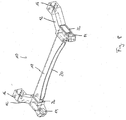
- Fig. 1 to 3 show in different views an axle module 10 in the form of a torsion beam axle for a motor vehicle, consisting of two arms 12, which are fastened via arranged at one end of the arm 12 sockets 14 on the vehicle body not shown here, at the area 16 carry the wheels of the axle and are connected to each other via an axle body 18, wherein the connection between the respective end region of the axle body 18 and the respective handlebar 12 is an adhesive connection.
- an axle module 10 in the form of a torsion beam axle for a motor vehicle, consisting of two arms 12, which are fastened via arranged at one end of the arm 12 sockets 14 on the vehicle body not shown here, at the area 16 carry the wheels of the axle and are connected to each other via an axle body 18, wherein the connection between the respective end region of the axle body 18 and the respective handlebar 12 is an adhesive connection.
- the axle body 18 is presently designed as an at least partially, namely in a region 20 between the end portions of the axle 18 unilaterally open hollow profile, that in each end in its end regions also open, but is closed like a tube over the circumference.
- the axle body 18 has a deviating from the circular cross section, wherein the cross section may be referred to as substantially rectangular.
- the link 12 has a receiving pin 22, onto which the respective end region of the axle body 18 is applied.
- Fig. 4 to 7 show four embodiments, as in an axle module 10 after Fig. 1 to 3 are applicable.
- Fig. 4 shows the adhesive bond between a conically widening in the direction of the receiving pin 22 end portion of the axle body and a conically widening in the direction of handlebar 12 spigot 22.
- the adhesive connection is made here over the entire surface between the outer shell of the receiving pin 22 and the recorded from the receiving pin 22 inner shell of this
- the adhesive 24 is thus distributed between said lateral surfaces and forms quasi in addition to the cohesive connection and sealing at the same time a spacer or insulation between the axle body 18 and its end and handlebar 12 and its receiving pin 22, so that thereby disadvantageous formation of a galvanic element with corresponding corrosion damage is prevented, for example, when using different metallic materials for axle 18 and arm 12 and spigot 22.
- Fig. 4 illustrated embodiment has the advantage that the end portion of the axle body 18 after the adhesive application to the receiving pin 22 and the inner shell of the end portion of the axle 18 relatively simple and the requirements according to the far on the conically widening spigot 22 can be postponed.
- the layer of adhesive 24 can be pressed relatively wide, so that an optimized adhesive bond arises.
- a relatively large surface is available in correlation with the length of the receiving pin 22.
- FIG. 5 The embodiment shown corresponds essentially to the embodiment Fig. 4 , however, unlike Fig. 4 a groove surrounding the receiving pin 22 in the handlebar 12 is introduced, wherein the groove quasi forms a receiving sleeve 26, in which a part of the end portion of the axle body 18 is introduced.
- receiving pin 22 and receiving sleeve 26 wherein the groove surrounding the receiving pin 22 with a predetermined depth advantageously forms a stop surface for the axle 18 applied to the respective end portion of the receiving pin 22, so that the positioning is reproducibly simplified. If the groove also fills with adhesive when gluing, it advantageously also constitutes a sealant at the same time.
- Fig. 6 illustrated embodiment shows alternative to the embodiment according to Fig. 5 a non-conically widening geometry of receiving pin 22 and end portion of the axle body 18th
- Fig. 7 illustrated embodiment shows alternative to the embodiment according to Fig. 5 a receiving pin 22 which is formed as a hollow profile.
- a receiving pin 22 which is formed as a hollow profile.
- Fig. 8 shows a further inventive axle module, wherein for the general description of the description of Fig. 1 can be referenced.
- the link 12 has a receiving sleeve 26 in the form of a hole open on both sides, into which the corresponding end region of the axle body 18 is introduced.
- the receiving sleeve 26 is flared to the side facing away from the axle 18 side of the arm 12 conically. This is in detail in Fig. 9 shown.
- the adhesive bond is made over the entire surface between the inner jacket of the receiving sleeve 26 and the outer jacket of the end region of the axle body 18 accommodated by the receiving sleeve 26, the adhesive in turn acting as a spacer.
- Fig. 10 shows a further inventive axle module, wherein for the general description of the description of Fig. 1 can be referenced.
- the link 12 has a receiving sleeve 26 in the form of a recess which widens conically on one side to the axle body 18 and into which the respective end region of the axle body 18 is introduced is.
- the end portion of the axle body 18 is also flared in the aforementioned direction.
- the end region of the axle body 18 is material-removing, in particular machined by machining.
- Fig. 12 shows a further inventive axle module, wherein for the general description of the description of Fig. 1 can be referenced.
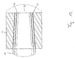
- the handlebar 12 has a receiving sleeve 26 in the form of a hole open on both sides to the axle body 18 in a conically widening hole into which the corresponding one conically tapers in the same direction widening end portion of the axle body 18 is introduced.
- connection is in detail in Fig. 13 shown.
- the adhesive bond is made over the entire surface between the inner jacket of the receiving sleeve 26 and the outer jacket of the end region of the axle body 18 accommodated by the receiving sleeve 26, the adhesive in turn acting as a spacer.
- longitudinal slots 28 are introduced, which facilitate or facilitate an assembly of axle body 18 and link 12, since the end region of the axle body 18 deforms during assembly in accordance with the conicity of the receiving sleeve 26.
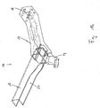
- Fig. 14 to 16 show a further inventive axis module, wherein for a general description of the description of Fig. 1 can be referenced.
- the adhesive bond is made over the entire surface between the inner jacket of the receiving sleeve 26 and the outer jacket of the end region of the axle body 18 accommodated by the receiving sleeve 26, the adhesive in turn acting as a spacer.
- Achsmodul 10 shown advantageously has within the axle body 18, a connecting element 30, preferably in the form of a tube or a rod which is screwed at its end to the respective handlebar 12 by means of screws 32, such that the connecting element 30 as one of the two links 12th connecting tie rod is effective.
- a connecting element 30 preferably in the form of a tube or a rod which is screwed at its end to the respective handlebar 12 by means of screws 32, such that the connecting element 30 as one of the two links 12th connecting tie rod is effective.
Landscapes
- Engineering & Computer Science (AREA)
- Mechanical Engineering (AREA)
- Vehicle Body Suspensions (AREA)
Claims (17)
- Module d'essieu (10) destiné à un véhicule à moteur, le module d'essieu étant constitué par deux guides d'essieu (12) qui peuvent être fixés à la carrosserie du véhicule, portent les roues de l'essieu et sont reliés l'un à l'autre via un corps d'essieu (18), la liaison entre le corps d'essieu (18) et le guide d'essieu respectif (12) étant une liaison collée, caractérisé en ce que chaque guide d'essieu (12) présente un dispositif de réception sous la forme d'un tenon de réception (22) et d'une rainure circulaire pour le corps d'essieu, rainure circulaire, qui est disposée dans le guide d'essieu (12) et entoure le tenon de réception (22).
- Module d'essieu (10) suivant le préambule de la revendication 1, caractérisé en ce qu'un élément de liaison (30), de préférence sous la forme d'un tube ou d'une barre, est disposé à l'intérieur du corps d'essieu (18), sur toute la longueur de celui-ci, élément de liaison, qui est relié, avec l'une de ses zones d'extrémité, à l'un des guide d'essieu et, avec l'autre zone d'extrémité, à l'autre guide d'essieu (12), la liaison moyennant l'élément de liaison (30) constituant une liaison supplémentaire à la liaison collée entre le corps d'essieu et le guide d'essieu respectif, l'élément de liaison (30) étant relié aux guide d'essieu (12) de façon qu'il agit comme un tirant reliant les deux guides d'essieu (12).
- Module d'essieu (10) suivant la revendication 2, caractérisé en ce que chacun des guides d'essieu (12) présente un dispositif de réception sous la forme d'une douille de réception (26) pour le corps d'essieu (18), douille de réception, qui est au moins partiellement ouverte à sa périphérie.
- Module d'essieu (10) suivant une des revendications 1 à 3, caractérisé en ce que le corps d'essieu (18) est, en outre, relié au guide d'essieu respectif (12) par vissage, agrafage, rivetage, sertissage, rabattement, assemblage par interpénétration.
- Module d'essieu (10) suivant une des revendications 1 à 4, caractérisé en ce que celui-ci (10), de préférence, le guide d'essieu respectif (12), est réalisé au moins partiellement en un matériau léger, le matériau léger étant, de préférence, un métal léger, une matière artificielle ou un composite de métal léger et de matière artificielle, le métal léger étant, de préférence, constitué d'aluminium, de magnésium, de zinc ou d'un composite d'alliages avec un ou plusieurs de ces métaux, la matière artificielle étant de préférence un polyamide, en particulier un polyamide renforcé par des fibres de verre.
- Module d'essieu (10) suivant la revendication 2, caractérisé en ce que chacun des guides d'essieu (12) présente un dispositif de réception pour le corps d'essieu (18), en particulier une douille de réception (26), en particulier comme rainure, et/ou un tenon de réception (22).
- Module d'essieu (10) suivant la revendication 1, caractérisé en ce que la rainure et/ou le tenon de réception (22) présentent au moins partiellement une section transversale, qui est au moins partiellement différente de la forme circulaire, la rainure et/ou le tenon de réception (22) étant, en section transversale, conçus de préférence sensiblement rectangulaire, carrée, ovale, triangulaire, polygonale ou trapézoïdale.
- Module d'essieu (10) suivant la revendication 1, caractérisé en ce que la rainure et/ou le tenon de réception (22) sont soit fermés soit partiellement ouverts à leur périphérie.
- Module d'essieu (10) suivant une des revendications 3 ou 6, caractérisé en ce que la liaison collée est réalisée au moins partiellement entre la paroi intérieure de la douille de réception et la paroi extérieure du corps d'essieu (18) reçue par la douille de réception, la liaison collée entre la paroi intérieure de la douille de réception (26) et la paroi extérieure du corps d'essieu (18), reçue par la douille de réception, étant de préférence réalisée de façon à recouvrir toute la surface.
- Module d'essieu (10) suivant une des revendications 1 ou 6 à 8, caractérisé en ce que la liaison collée est réalisée au moins partiellement entre la paroi extérieure du tenon de réception (22) et la paroi intérieure, reçue par le tenon de réception (22), du corps d'essieu, qui est, au moins dans cette zone, conçu en forme de tube, la liaison collée entre la paroi extérieure du tenon de réception (22) et la paroi intérieure, reçue par le tenon de réception (22), du corps d'essieu (18) qui est, au moins dans cette zone, conçu en forme de tube, est réalisée de façon à recouvrir toute la surface.
- Module d'essieu (10) suivant une des revendications 1 à 10, caractérisé en ce que la liaison collée est telle que la colle (24) agit comme écarteur entre le guide d'essieu respectif (12) et le corps d'essieu (18).
- Module d'essieu (10) suivant la revendication 1, caractérisé en ce que la rainure et/ou le tenon de réception (22) sont au moins partiellement intégrés dans le guide d'essieu (12) ou formés par celui-ci.
- Module d'essieu (10) suivant la revendication 6, caractérisé en ce que la douille de réception (26) et/ou le tenon de réception (22) sont au moins partiellement intégrés dans le guide d'essieu (12) ou formés par celui-ci.
- Module d'essieu (10) suivant une des revendications 1, 3 ou 6, caractérisé en ce que le guide d'essieu (12) et le dispositif de réception sont réalisés comme composant moulé formant une seule pièce ou en ce que le dispositif de réception est une pièce réalisée séparément du moulage du guide d'essieu (12) qui est au moins partiellement encapsulée dans le guide d'essieu (12).
- Module d'essieu (10) suivant une des revendications 1, 3, 6 ou 14, caractérisé en ce qu'au moins une partie du dispositif de réception ou le composant moulé est réalisé par moulage par compression, moulage en coquille par contre-pression (CPC), moulage sous pression, moulage en sable thixiotropique, rhéologique et basse pression ou moulage en coquille par gravité.
- Module d'essieu (10) suivant une des revendications 1 à 13, caractérisé en ce que le guide d'essieu (12), le dispositif de réception et/ou le corps d'essieu sont conçus au moins partiellement comme profilé moulé par injection, extrusion, coulée en continu ou de préférence comme profilé moulé.
- Module d'essieu (10) suivant la revendication 6, caractérisé en ce que la douille de réception (26) et/ou le tenon de réception (22) présentent une forme transversale qui est au moins partiellement différente de la forme circulaire, la douille de réception (26) et/ou le tenon de réception (22) étant, en section transversale, conçus de préférence sensiblement rectangulaire, carrée, ovale, triangulaire, polygonale ou trapézoïdale.
Applications Claiming Priority (3)
| Application Number | Priority Date | Filing Date | Title |
|---|---|---|---|
| DE102010021674 | 2010-05-27 | ||
| DE102011103093 | 2011-05-26 | ||
| PCT/DE2011/001157 WO2011147411A2 (fr) | 2010-05-27 | 2011-05-27 | Module d'essieu, en particulier essieu à bras combinés |
Publications (2)
| Publication Number | Publication Date |
|---|---|
| EP2576248A2 EP2576248A2 (fr) | 2013-04-10 |
| EP2576248B1 true EP2576248B1 (fr) | 2016-06-22 |
Family
ID=44924938
Family Applications (1)
| Application Number | Title | Priority Date | Filing Date |
|---|---|---|---|
| EP11735776.4A Not-in-force EP2576248B1 (fr) | 2010-05-27 | 2011-05-27 | Module d'essieu, en particulier essieu à bras combinés |
Country Status (5)
| Country | Link |
|---|---|
| US (1) | US8870204B2 (fr) |
| EP (1) | EP2576248B1 (fr) |
| CN (1) | CN102933409B (fr) |
| DE (2) | DE112011104282A5 (fr) |
| WO (1) | WO2011147411A2 (fr) |
Families Citing this family (25)
| Publication number | Priority date | Publication date | Assignee | Title |
|---|---|---|---|---|
| DE102011079979A1 (de) * | 2011-07-28 | 2013-01-31 | Zf Friedrichshafen Ag | Verbundlenkerachse |
| DE102011086481B4 (de) * | 2011-11-16 | 2020-06-10 | Saf-Holland Gmbh | Fahrwerksystem für Nutzfahrzeuge |
| DE102012017941A1 (de) * | 2012-09-12 | 2014-03-13 | GM Global Technology Operations LLC (n. d. Gesetzen des Staates Delaware) | Verbundlenker-Hinterachse |
| DE102012017940A1 (de) * | 2012-09-12 | 2014-03-13 | GM Global Technology Operations LLC (n. d. Gesetzen des Staates Delaware) | Verbundlenker-Hinterachse |
| BR112015017953A2 (pt) * | 2013-01-30 | 2017-07-11 | Nippon Steel & Sumitomo Metal Corp | barra de torsão, montagem de barra de torsão, e sistema de suspensão do tipo barra de torsão |
| DE202013004035U1 (de) | 2013-04-30 | 2014-08-01 | Cosma Engineering Europe Ag | Baugruppe für ein Fahrzeug |
| JP6131787B2 (ja) * | 2013-09-03 | 2017-05-24 | トヨタ自動車株式会社 | 車両用サスペンションアーム |
| RU2639362C2 (ru) * | 2013-10-09 | 2017-12-21 | Ниппон Стил Энд Сумитомо Метал Корпорейшн | Конструктивный элемент для автомобильного кузова |
| JP6195069B2 (ja) * | 2014-03-18 | 2017-09-13 | マツダ株式会社 | 車両のサスペンションの取付構造 |
| FR3024398B1 (fr) * | 2014-07-31 | 2018-06-15 | Renault S.A.S. | Suspension de vehicule automobile a barre de torsion composite collee |
| CN105564184B (zh) * | 2014-10-09 | 2019-01-18 | 广州汽车集团股份有限公司 | 扭力梁结构及扭力梁式悬架 |
| CN106794738A (zh) * | 2014-10-14 | 2017-05-31 | 麦格纳国际公司 | 车辆扭转车桥组件 |
| DE102015201625A1 (de) * | 2015-01-30 | 2016-08-04 | Zf Friedrichshafen Ag | Verbundlenkerachse für ein Kraftfahrzeug |
| WO2016133753A1 (fr) * | 2015-02-20 | 2016-08-25 | Magna International Inc. | Ensemble essieu de torsion de véhicule |
| DE102016214532A1 (de) * | 2015-08-20 | 2017-02-23 | Ford Global Technologies, Llc | Hilfsrahmen für ein Kraftfahrzeug |
| DE102015223314A1 (de) * | 2015-11-25 | 2017-06-01 | Zf Friedrichshafen Ag | Verbundlenkerachse, Verfahren zur Herstellung einer Verbundlenkerachse und Fahrzeug mit einer Verbundlenkerachse |
| DE102015223317A1 (de) * | 2015-11-25 | 2017-06-01 | Zf Friedrichshafen Ag | Verbundlenkerachse, Verfahren zur Herstellung einer Verbundlenkerachse und Fahrzeug mit einer Verbundlenkerachse |
| DE102015223808A1 (de) * | 2015-12-01 | 2017-06-01 | Zf Friedrichshafen Ag | Verbundlenkerachse, Verfahren zur Herstellung einer Verbundlenkerachse und Fahrzeug mit einer Verbundlenkerachse |
| FR3044600B1 (fr) * | 2015-12-08 | 2019-11-22 | Renault S.A.S. | "procede de realisation d'un essieu arriere de vehicule automobile par frettage d'une traverse dans un bras" |
| DE102016206283A1 (de) * | 2016-04-14 | 2017-10-19 | Zf Friedrichshafen Ag | Verbundlenkerachse, Verfahren zur Herstellung einer Verbundlenkerachse und Fahrzeug mit einer Verbundlenkerachse |
| DE202016105937U1 (de) * | 2016-10-21 | 2018-01-24 | Deutsches Zentrum für Luft- und Raumfahrt e.V. | Fahrwerksachse und Kraftfahrzeug |
| WO2019191567A1 (fr) * | 2018-03-29 | 2019-10-03 | Magna International Inc. | Ensemble essieu de torsion de véhicule |
| DE102020103762B4 (de) | 2020-02-13 | 2023-10-12 | Saf-Holland Gmbh | Lenkersystem |
| DE102022201246A1 (de) | 2022-02-07 | 2023-08-10 | Volkswagen Aktiengesellschaft | Verfahren zur Herstellung eines Hilfsrahmens für ein Fahrzeug und Hilfsrahmen |
| DE102023105503A1 (de) * | 2023-03-07 | 2024-09-12 | Bayerische Motoren Werke Aktiengesellschaft | Strukturelement für ein Kraftrad, insbesondere für ein Motorrad, Kraftrad sowie Verfahren zum Herstellen eines solchen Strukturelements |
Citations (2)
| Publication number | Priority date | Publication date | Assignee | Title |
|---|---|---|---|---|
| DE19603764A1 (de) * | 1996-02-02 | 1997-08-07 | Opel Adam Ag | Verbundlenker-Hinterachse |
| FR2811938A1 (fr) * | 2000-07-18 | 2002-01-25 | Peugeot Citroen Automobiles Sa | Dispositif de fixation d'une traverse pour train arriere d'un vehicule automobile |
Family Cites Families (10)
| Publication number | Priority date | Publication date | Assignee | Title |
|---|---|---|---|---|
| DE3447036A1 (de) * | 1984-12-22 | 1986-07-10 | Audi AG, 8070 Ingolstadt | Formschluessige verbindung zwischen einem profilstab und einem knotenelement |
| DE19535521A1 (de) | 1994-10-07 | 1996-04-11 | Volkswagen Ag | Verbundlenkerachse für die Hinterräder eines Kraftfahrzeugs |
| DE19542522A1 (de) * | 1995-11-15 | 1997-05-22 | Opel Adam Ag | Verbundlenker-Hinterachse |
| DE19752347B4 (de) * | 1996-12-07 | 2006-06-01 | Volkswagen Ag | Verbundlenker-Hinterachse und Verfahren zu ihrer Herstellung |
| DE50013730D1 (de) * | 1999-03-17 | 2006-12-28 | Benteler Werke Ag | Verbundlenkerachse für Kraftfahrzeuge |
| DE10357885B4 (de) * | 2003-12-11 | 2007-10-11 | Benteler Automobiltechnik Gmbh | Torsionsachse |
| FR2888559B1 (fr) * | 2005-07-15 | 2008-09-26 | Renault Sas | Procede d'assemblage d'un essieu de vehicule automobile du type pourvu de bras de suspension et d'une traverse montee entre lesdits bras, et essieu correspondant |
| FR2908347B1 (fr) * | 2006-11-09 | 2009-11-06 | Renault Sas | Assemblage d'un essieu arriere de vehicule. |
| WO2008095286A1 (fr) * | 2007-02-06 | 2008-08-14 | Magna International Inc. | Soudage avec décharge de condensateurs pour raccorder des profils tubulaires enroulés de poutres afin de mouler un bras de torsion via une bague adaptatrice |
| DE102008003552A1 (de) * | 2008-01-09 | 2009-08-06 | Benteler Automobiltechnik Gmbh | Verfahren zum Verbinden von Bauteilen, insbesondere Fahrzeugachskomponenten |
-
2011
- 2011-05-27 DE DE112011104282T patent/DE112011104282A5/de not_active Withdrawn
- 2011-05-27 US US13/699,901 patent/US8870204B2/en active Active
- 2011-05-27 CN CN201180026245.6A patent/CN102933409B/zh not_active Expired - Fee Related
- 2011-05-27 DE DE102011103847A patent/DE102011103847A1/de not_active Withdrawn
- 2011-05-27 EP EP11735776.4A patent/EP2576248B1/fr not_active Not-in-force
- 2011-05-27 WO PCT/DE2011/001157 patent/WO2011147411A2/fr not_active Ceased
Patent Citations (2)
| Publication number | Priority date | Publication date | Assignee | Title |
|---|---|---|---|---|
| DE19603764A1 (de) * | 1996-02-02 | 1997-08-07 | Opel Adam Ag | Verbundlenker-Hinterachse |
| FR2811938A1 (fr) * | 2000-07-18 | 2002-01-25 | Peugeot Citroen Automobiles Sa | Dispositif de fixation d'une traverse pour train arriere d'un vehicule automobile |
Also Published As
| Publication number | Publication date |
|---|---|
| US20130093156A1 (en) | 2013-04-18 |
| WO2011147411A3 (fr) | 2012-05-24 |
| US8870204B2 (en) | 2014-10-28 |
| WO2011147411A2 (fr) | 2011-12-01 |
| CN102933409B (zh) | 2016-02-24 |
| DE102011103847A1 (de) | 2011-12-01 |
| DE112011104282A5 (de) | 2013-09-05 |
| CN102933409A (zh) | 2013-02-13 |
| EP2576248A2 (fr) | 2013-04-10 |
Similar Documents
| Publication | Publication Date | Title |
|---|---|---|
| EP2576248B1 (fr) | Module d'essieu, en particulier essieu à bras combinés | |
| EP2729347B1 (fr) | Support d'essieu à support intégré pour un entraînement | |
| EP2736733B1 (fr) | Système de châssis pour véhicules utilitaires | |
| EP1690779B1 (fr) | Châssis auxiliaire pour véhicules automobiles | |
| EP1912806B2 (fr) | Bras oscillant de suspension | |
| DE102012016268B4 (de) | Verbindungsanordnung sowie Querträger mit einer solchen Verbindungsanordnung. | |
| EP1989069B1 (fr) | Bras de suspension en fonte a douille en acier integree | |
| EP1036680B1 (fr) | Essieu à traverse déformable en torsion pour un véhicule automobile | |
| EP2329159A1 (fr) | Dispositif de liaison d'arbre creux | |
| DE202013004035U1 (de) | Baugruppe für ein Fahrzeug | |
| EP2547539B1 (fr) | Supports de roue pour suspension independant ayant plusieurs bras oscillants | |
| DE102012021289B4 (de) | Fahrzeugachse für ein Kraftfahrzeug sowie Kraftfahrzeug mit einer derartigen Fahrzeugachse | |
| DE102013003300A1 (de) | Fahrwerk für ein Nutzfahrzeug, Achskörper sowie Verfahren zum Herstellen eines Achskörpers | |
| EP2888153B1 (fr) | Ensemble palier et support d'essieu pour véhicule à moteur | |
| EP1826100B1 (fr) | Montage composite pour un véhicule utilitaire à suspension pneumatique | |
| DE102009004310A1 (de) | Fahrschemel, insbesondere Vorderachsträger | |
| DE102011101581A1 (de) | Träger, insbesondere Instrumententafel-Querträger, für ein Fahrzeug und Verfahren zur Herstellung eines Trägers | |
| EP1645445B1 (fr) | Suspension avec ressort à lames | |
| WO2019206622A1 (fr) | Suspension de véhicule automobile | |
| DE102012009458B4 (de) | Lager zum elastischen Koppeln zweier Bauteile | |
| EP2617629B1 (fr) | Noeud de carrosserie | |
| DE102013225334A1 (de) | Lenker eines Fahrwerks für Kraftfahrzeuge | |
| DE102010030644B4 (de) | Verbundlenkerachse für Kraftfahrzeuge | |
| WO2012025096A1 (fr) | Bras oscillant longitudinal pour véhicules automobiles | |
| EP2455635B1 (fr) | Ressort à lame et procédé de fabrication d'un tel ressort à lame |
Legal Events
| Date | Code | Title | Description |
|---|---|---|---|
| PUAI | Public reference made under article 153(3) epc to a published international application that has entered the european phase |
Free format text: ORIGINAL CODE: 0009012 |
|
| 17P | Request for examination filed |
Effective date: 20121210 |
|
| AK | Designated contracting states |
Kind code of ref document: A2 Designated state(s): AL AT BE BG CH CY CZ DE DK EE ES FI FR GB GR HR HU IE IS IT LI LT LU LV MC MK MT NL NO PL PT RO RS SE SI SK SM TR |
|
| DAX | Request for extension of the european patent (deleted) | ||
| 17Q | First examination report despatched |
Effective date: 20140120 |
|
| GRAP | Despatch of communication of intention to grant a patent |
Free format text: ORIGINAL CODE: EPIDOSNIGR1 |
|
| INTG | Intention to grant announced |
Effective date: 20160302 |
|
| GRAS | Grant fee paid |
Free format text: ORIGINAL CODE: EPIDOSNIGR3 |
|
| GRAA | (expected) grant |
Free format text: ORIGINAL CODE: 0009210 |
|
| AK | Designated contracting states |
Kind code of ref document: B1 Designated state(s): AL AT BE BG CH CY CZ DE DK EE ES FI FR GB GR HR HU IE IS IT LI LT LU LV MC MK MT NL NO PL PT RO RS SE SI SK SM TR |
|
| REG | Reference to a national code |
Ref country code: GB Ref legal event code: FG4D Free format text: NOT ENGLISH |
|
| REG | Reference to a national code |
Ref country code: CH Ref legal event code: EP |
|
| REG | Reference to a national code |
Ref country code: IE Ref legal event code: FG4D Free format text: LANGUAGE OF EP DOCUMENT: GERMAN |
|
| REG | Reference to a national code |
Ref country code: AT Ref legal event code: REF Ref document number: 807439 Country of ref document: AT Kind code of ref document: T Effective date: 20160715 |
|
| REG | Reference to a national code |
Ref country code: DE Ref legal event code: R096 Ref document number: 502011010003 Country of ref document: DE |
|
| REG | Reference to a national code |
Ref country code: LT Ref legal event code: MG4D |
|
| REG | Reference to a national code |
Ref country code: NL Ref legal event code: MP Effective date: 20160622 |
|
| PG25 | Lapsed in a contracting state [announced via postgrant information from national office to epo] |
Ref country code: LT Free format text: LAPSE BECAUSE OF FAILURE TO SUBMIT A TRANSLATION OF THE DESCRIPTION OR TO PAY THE FEE WITHIN THE PRESCRIBED TIME-LIMIT Effective date: 20160622 Ref country code: NO Free format text: LAPSE BECAUSE OF FAILURE TO SUBMIT A TRANSLATION OF THE DESCRIPTION OR TO PAY THE FEE WITHIN THE PRESCRIBED TIME-LIMIT Effective date: 20160922 Ref country code: FI Free format text: LAPSE BECAUSE OF FAILURE TO SUBMIT A TRANSLATION OF THE DESCRIPTION OR TO PAY THE FEE WITHIN THE PRESCRIBED TIME-LIMIT Effective date: 20160622 |
|
| PG25 | Lapsed in a contracting state [announced via postgrant information from national office to epo] |
Ref country code: HR Free format text: LAPSE BECAUSE OF FAILURE TO SUBMIT A TRANSLATION OF THE DESCRIPTION OR TO PAY THE FEE WITHIN THE PRESCRIBED TIME-LIMIT Effective date: 20160622 Ref country code: NL Free format text: LAPSE BECAUSE OF FAILURE TO SUBMIT A TRANSLATION OF THE DESCRIPTION OR TO PAY THE FEE WITHIN THE PRESCRIBED TIME-LIMIT Effective date: 20160622 Ref country code: SE Free format text: LAPSE BECAUSE OF FAILURE TO SUBMIT A TRANSLATION OF THE DESCRIPTION OR TO PAY THE FEE WITHIN THE PRESCRIBED TIME-LIMIT Effective date: 20160622 Ref country code: LV Free format text: LAPSE BECAUSE OF FAILURE TO SUBMIT A TRANSLATION OF THE DESCRIPTION OR TO PAY THE FEE WITHIN THE PRESCRIBED TIME-LIMIT Effective date: 20160622 Ref country code: RS Free format text: LAPSE BECAUSE OF FAILURE TO SUBMIT A TRANSLATION OF THE DESCRIPTION OR TO PAY THE FEE WITHIN THE PRESCRIBED TIME-LIMIT Effective date: 20160622 Ref country code: GR Free format text: LAPSE BECAUSE OF FAILURE TO SUBMIT A TRANSLATION OF THE DESCRIPTION OR TO PAY THE FEE WITHIN THE PRESCRIBED TIME-LIMIT Effective date: 20160923 |
|
| PG25 | Lapsed in a contracting state [announced via postgrant information from national office to epo] |
Ref country code: CZ Free format text: LAPSE BECAUSE OF FAILURE TO SUBMIT A TRANSLATION OF THE DESCRIPTION OR TO PAY THE FEE WITHIN THE PRESCRIBED TIME-LIMIT Effective date: 20160622 Ref country code: SK Free format text: LAPSE BECAUSE OF FAILURE TO SUBMIT A TRANSLATION OF THE DESCRIPTION OR TO PAY THE FEE WITHIN THE PRESCRIBED TIME-LIMIT Effective date: 20160622 Ref country code: RO Free format text: LAPSE BECAUSE OF FAILURE TO SUBMIT A TRANSLATION OF THE DESCRIPTION OR TO PAY THE FEE WITHIN THE PRESCRIBED TIME-LIMIT Effective date: 20160622 Ref country code: EE Free format text: LAPSE BECAUSE OF FAILURE TO SUBMIT A TRANSLATION OF THE DESCRIPTION OR TO PAY THE FEE WITHIN THE PRESCRIBED TIME-LIMIT Effective date: 20160622 Ref country code: IS Free format text: LAPSE BECAUSE OF FAILURE TO SUBMIT A TRANSLATION OF THE DESCRIPTION OR TO PAY THE FEE WITHIN THE PRESCRIBED TIME-LIMIT Effective date: 20161022 Ref country code: IT Free format text: LAPSE BECAUSE OF FAILURE TO SUBMIT A TRANSLATION OF THE DESCRIPTION OR TO PAY THE FEE WITHIN THE PRESCRIBED TIME-LIMIT Effective date: 20160622 |
|
| PG25 | Lapsed in a contracting state [announced via postgrant information from national office to epo] |
Ref country code: PL Free format text: LAPSE BECAUSE OF FAILURE TO SUBMIT A TRANSLATION OF THE DESCRIPTION OR TO PAY THE FEE WITHIN THE PRESCRIBED TIME-LIMIT Effective date: 20160622 Ref country code: SM Free format text: LAPSE BECAUSE OF FAILURE TO SUBMIT A TRANSLATION OF THE DESCRIPTION OR TO PAY THE FEE WITHIN THE PRESCRIBED TIME-LIMIT Effective date: 20160622 Ref country code: PT Free format text: LAPSE BECAUSE OF FAILURE TO SUBMIT A TRANSLATION OF THE DESCRIPTION OR TO PAY THE FEE WITHIN THE PRESCRIBED TIME-LIMIT Effective date: 20161024 Ref country code: ES Free format text: LAPSE BECAUSE OF FAILURE TO SUBMIT A TRANSLATION OF THE DESCRIPTION OR TO PAY THE FEE WITHIN THE PRESCRIBED TIME-LIMIT Effective date: 20160622 |
|
| REG | Reference to a national code |
Ref country code: DE Ref legal event code: R097 Ref document number: 502011010003 Country of ref document: DE |
|
| PLBE | No opposition filed within time limit |
Free format text: ORIGINAL CODE: 0009261 |
|
| STAA | Information on the status of an ep patent application or granted ep patent |
Free format text: STATUS: NO OPPOSITION FILED WITHIN TIME LIMIT |
|
| REG | Reference to a national code |
Ref country code: FR Ref legal event code: PLFP Year of fee payment: 7 |
|
| 26N | No opposition filed |
Effective date: 20170323 |
|
| PG25 | Lapsed in a contracting state [announced via postgrant information from national office to epo] |
Ref country code: DK Free format text: LAPSE BECAUSE OF FAILURE TO SUBMIT A TRANSLATION OF THE DESCRIPTION OR TO PAY THE FEE WITHIN THE PRESCRIBED TIME-LIMIT Effective date: 20160622 |
|
| PG25 | Lapsed in a contracting state [announced via postgrant information from national office to epo] |
Ref country code: LU Free format text: LAPSE BECAUSE OF NON-PAYMENT OF DUE FEES Effective date: 20170531 Ref country code: SI Free format text: LAPSE BECAUSE OF FAILURE TO SUBMIT A TRANSLATION OF THE DESCRIPTION OR TO PAY THE FEE WITHIN THE PRESCRIBED TIME-LIMIT Effective date: 20160622 |
|
| REG | Reference to a national code |
Ref country code: CH Ref legal event code: PL |
|
| PG25 | Lapsed in a contracting state [announced via postgrant information from national office to epo] |
Ref country code: MC Free format text: LAPSE BECAUSE OF FAILURE TO SUBMIT A TRANSLATION OF THE DESCRIPTION OR TO PAY THE FEE WITHIN THE PRESCRIBED TIME-LIMIT Effective date: 20160622 |
|
| REG | Reference to a national code |
Ref country code: IE Ref legal event code: MM4A |
|
| PG25 | Lapsed in a contracting state [announced via postgrant information from national office to epo] |
Ref country code: LI Free format text: LAPSE BECAUSE OF NON-PAYMENT OF DUE FEES Effective date: 20170531 Ref country code: CH Free format text: LAPSE BECAUSE OF NON-PAYMENT OF DUE FEES Effective date: 20170531 |
|
| PG25 | Lapsed in a contracting state [announced via postgrant information from national office to epo] |
Ref country code: LU Free format text: LAPSE BECAUSE OF NON-PAYMENT OF DUE FEES Effective date: 20170527 |
|
| REG | Reference to a national code |
Ref country code: BE Ref legal event code: MM Effective date: 20170531 |
|
| PG25 | Lapsed in a contracting state [announced via postgrant information from national office to epo] |
Ref country code: IE Free format text: LAPSE BECAUSE OF NON-PAYMENT OF DUE FEES Effective date: 20170527 |
|
| REG | Reference to a national code |
Ref country code: FR Ref legal event code: PLFP Year of fee payment: 8 |
|
| REG | Reference to a national code |
Ref country code: AT Ref legal event code: MM01 Ref document number: 807439 Country of ref document: AT Kind code of ref document: T Effective date: 20170527 |
|
| PG25 | Lapsed in a contracting state [announced via postgrant information from national office to epo] |
Ref country code: AT Free format text: LAPSE BECAUSE OF NON-PAYMENT OF DUE FEES Effective date: 20170527 Ref country code: BE Free format text: LAPSE BECAUSE OF NON-PAYMENT OF DUE FEES Effective date: 20170531 |
|
| PG25 | Lapsed in a contracting state [announced via postgrant information from national office to epo] |
Ref country code: MT Free format text: LAPSE BECAUSE OF FAILURE TO SUBMIT A TRANSLATION OF THE DESCRIPTION OR TO PAY THE FEE WITHIN THE PRESCRIBED TIME-LIMIT Effective date: 20160622 |
|
| PG25 | Lapsed in a contracting state [announced via postgrant information from national office to epo] |
Ref country code: AL Free format text: LAPSE BECAUSE OF FAILURE TO SUBMIT A TRANSLATION OF THE DESCRIPTION OR TO PAY THE FEE WITHIN THE PRESCRIBED TIME-LIMIT Effective date: 20160622 |
|
| PG25 | Lapsed in a contracting state [announced via postgrant information from national office to epo] |
Ref country code: HU Free format text: LAPSE BECAUSE OF FAILURE TO SUBMIT A TRANSLATION OF THE DESCRIPTION OR TO PAY THE FEE WITHIN THE PRESCRIBED TIME-LIMIT; INVALID AB INITIO Effective date: 20110527 |
|
| PG25 | Lapsed in a contracting state [announced via postgrant information from national office to epo] |
Ref country code: BG Free format text: LAPSE BECAUSE OF FAILURE TO SUBMIT A TRANSLATION OF THE DESCRIPTION OR TO PAY THE FEE WITHIN THE PRESCRIBED TIME-LIMIT Effective date: 20160622 |
|
| PGFP | Annual fee paid to national office [announced via postgrant information from national office to epo] |
Ref country code: FR Payment date: 20190528 Year of fee payment: 9 |
|
| PG25 | Lapsed in a contracting state [announced via postgrant information from national office to epo] |
Ref country code: CY Free format text: LAPSE BECAUSE OF NON-PAYMENT OF DUE FEES Effective date: 20160622 |
|
| PGFP | Annual fee paid to national office [announced via postgrant information from national office to epo] |
Ref country code: GB Payment date: 20190529 Year of fee payment: 9 |
|
| PG25 | Lapsed in a contracting state [announced via postgrant information from national office to epo] |
Ref country code: MK Free format text: LAPSE BECAUSE OF FAILURE TO SUBMIT A TRANSLATION OF THE DESCRIPTION OR TO PAY THE FEE WITHIN THE PRESCRIBED TIME-LIMIT Effective date: 20160622 |
|
| PG25 | Lapsed in a contracting state [announced via postgrant information from national office to epo] |
Ref country code: TR Free format text: LAPSE BECAUSE OF FAILURE TO SUBMIT A TRANSLATION OF THE DESCRIPTION OR TO PAY THE FEE WITHIN THE PRESCRIBED TIME-LIMIT Effective date: 20160622 |
|
| GBPC | Gb: european patent ceased through non-payment of renewal fee |
Effective date: 20200527 |
|
| PG25 | Lapsed in a contracting state [announced via postgrant information from national office to epo] |
Ref country code: GB Free format text: LAPSE BECAUSE OF NON-PAYMENT OF DUE FEES Effective date: 20200527 Ref country code: FR Free format text: LAPSE BECAUSE OF NON-PAYMENT OF DUE FEES Effective date: 20200531 |
|
| PGFP | Annual fee paid to national office [announced via postgrant information from national office to epo] |
Ref country code: DE Payment date: 20220527 Year of fee payment: 12 |
|
| REG | Reference to a national code |
Ref country code: DE Ref legal event code: R119 Ref document number: 502011010003 Country of ref document: DE |
|
| PG25 | Lapsed in a contracting state [announced via postgrant information from national office to epo] |
Ref country code: DE Free format text: LAPSE BECAUSE OF NON-PAYMENT OF DUE FEES Effective date: 20231201 |