EP2576268B1 - Bedienvorrichtung für ein fahrzeug - Google Patents
Bedienvorrichtung für ein fahrzeug Download PDFInfo
- Publication number
- EP2576268B1 EP2576268B1 EP11721053.4A EP11721053A EP2576268B1 EP 2576268 B1 EP2576268 B1 EP 2576268B1 EP 11721053 A EP11721053 A EP 11721053A EP 2576268 B1 EP2576268 B1 EP 2576268B1
- Authority
- EP
- European Patent Office
- Prior art keywords
- fluid
- operating
- switch
- operating device
- operating element
- Prior art date
- Legal status (The legal status is an assumption and is not a legal conclusion. Google has not performed a legal analysis and makes no representation as to the accuracy of the status listed.)
- Not-in-force
Links
Images

Classifications
-
- B—PERFORMING OPERATIONS; TRANSPORTING
- B60—VEHICLES IN GENERAL
- B60K—ARRANGEMENT OR MOUNTING OF PROPULSION UNITS OR OF TRANSMISSIONS IN VEHICLES; ARRANGEMENT OR MOUNTING OF PLURAL DIVERSE PRIME-MOVERS IN VEHICLES; AUXILIARY DRIVES FOR VEHICLES; INSTRUMENTATION OR DASHBOARDS FOR VEHICLES; ARRANGEMENTS IN CONNECTION WITH COOLING, AIR INTAKE, GAS EXHAUST OR FUEL SUPPLY OF PROPULSION UNITS IN VEHICLES
- B60K35/00—Instruments specially adapted for vehicles; Arrangement of instruments in or on vehicles
- B60K35/10—Input arrangements, i.e. from user to vehicle, associated with vehicle functions or specially adapted therefor
-
- G—PHYSICS
- G06—COMPUTING OR CALCULATING; COUNTING
- G06F—ELECTRIC DIGITAL DATA PROCESSING
- G06F3/00—Input arrangements for transferring data to be processed into a form capable of being handled by the computer; Output arrangements for transferring data from processing unit to output unit, e.g. interface arrangements
- G06F3/01—Input arrangements or combined input and output arrangements for interaction between user and computer
- G06F3/02—Input arrangements using manually operated switches, e.g. using keyboards or dials
- G06F3/0202—Constructional details or processes of manufacture of the input device
-
- H—ELECTRICITY
- H01—ELECTRIC ELEMENTS
- H01H—ELECTRIC SWITCHES; RELAYS; SELECTORS; EMERGENCY PROTECTIVE DEVICES
- H01H13/00—Switches having rectilinearly-movable operating part or parts adapted for pushing or pulling in one direction only, e.g. push-button switch
- H01H13/70—Switches having rectilinearly-movable operating part or parts adapted for pushing or pulling in one direction only, e.g. push-button switch having a plurality of operating members associated with different sets of contacts, e.g. keyboard
- H01H13/702—Switches having rectilinearly-movable operating part or parts adapted for pushing or pulling in one direction only, e.g. push-button switch having a plurality of operating members associated with different sets of contacts, e.g. keyboard with contacts carried by or formed from layers in a multilayer structure, e.g. membrane switches
- H01H13/705—Switches having rectilinearly-movable operating part or parts adapted for pushing or pulling in one direction only, e.g. push-button switch having a plurality of operating members associated with different sets of contacts, e.g. keyboard with contacts carried by or formed from layers in a multilayer structure, e.g. membrane switches characterised by construction, mounting or arrangement of operating parts, e.g. push-buttons or keys
- H01H13/7065—Switches having rectilinearly-movable operating part or parts adapted for pushing or pulling in one direction only, e.g. push-button switch having a plurality of operating members associated with different sets of contacts, e.g. keyboard with contacts carried by or formed from layers in a multilayer structure, e.g. membrane switches characterised by construction, mounting or arrangement of operating parts, e.g. push-buttons or keys characterised by the mechanism between keys and layered keyboards
-
- H—ELECTRICITY
- H01—ELECTRIC ELEMENTS
- H01H—ELECTRIC SWITCHES; RELAYS; SELECTORS; EMERGENCY PROTECTIVE DEVICES
- H01H2221/00—Actuators
- H01H2221/036—Return force
- H01H2221/038—Fluid
-
- H—ELECTRICITY
- H01—ELECTRIC ELEMENTS
- H01H—ELECTRIC SWITCHES; RELAYS; SELECTORS; EMERGENCY PROTECTIVE DEVICES
- H01H2221/00—Actuators
- H01H2221/09—Flexible integral part of housing
-
- H—ELECTRICITY
- H01—ELECTRIC ELEMENTS
- H01H—ELECTRIC SWITCHES; RELAYS; SELECTORS; EMERGENCY PROTECTIVE DEVICES
- H01H2223/00—Casings
- H01H2223/002—Casings sealed
Definitions
- the invention relates to an operating device for a vehicle.
- the operating device comprises an operating element which can be actuated by an operator, as well as an electrical switch which can be actuated as a function of an actuation of the operating element.
- the operating device also comprises transmission means which serve for transmitting an actuating pressure from the operating element to the switch.
- Such operating devices are state of the art and thus known, namely, for example, from the document CN 201134365 Y and the publication JP 1258325 A .
- the transmission of the actuating pressure by means of a movable mechanical element - for example, a plunger takes place.
- a movable mechanical element for example, a plunger
- Such operating devices is to be regarded as a disadvantage of the fact that they have a variety of components that must be coordinated. In particular, only very small deviations of the dimensions of the components of a nominal size can be allowed, which is sometimes difficult to achieve in production. It is also disadvantageous that a correspondingly large depth is required for such mechanical operating devices - this due to the large number of components.
- the document WO 2007/014780 A1 describes a control for motor vehicles.
- a push button is slidably mounted in a housing.
- touch-sensitive operating devices are known in which also the principle of the evaluation of a capacitance change is used.
- the capacitive operating devices generally have the disadvantage that the operator receives no haptic feedback when operating the operating device. Depending on the speed of the capacity change, it may not be possible to quickly evaluate this change.
- a switch for a keyboard which comprises a fluid-filled cushion arranged between the control element and the switch in order to produce a desired feel.
- the operating device also includes an electrical switch, which is actuated depending on an actuation of the operating element.
- Transmission means are provided which serve to transmit an actuating pressure from the operating element to the switch.
- the transmission means comprise a fluid for transmitting the actuating pressure.
- the operating pressure which an operator exerts on the operating element is transmitted to the electrical switch by a fluid.
- the invention has various advantages: On the one hand, a small overall depth in the operating device is possible - a thin operating device can be provided. On the other hand, the power transmission from the operating element to the switch can be effected virtually friction-free and thus wear-resistant. The transmission of the actuating pressure can also take place over longer distances within the operating device, so that the switch can be arranged virtually anywhere regardless of the operating point. This proves to be particularly advantageous in motor vehicles:
- the control element can be arranged, for example, at a first location in the vehicle - for example on a center console - while the switch with an electronic module can be located at a remote second location.
- the fluid also provides a haptic feedback to the operator when operating the control element; For example, here a haptic feedback of the switch on the fluid can be transferred back to the control element.
- Remain operating device namely that it can be made visually appealing due to the presence of the fluid.
- the control element can be illuminated, namely, for example, symbols attached to the control element.
- the operating element is also made of a light-transmitting material, an additional visual effect results for the operator.
- the operating device includes a fluid which serves to transmit the actuating pressure.
- a fluid is understood to mean, in particular, such a medium in which, when a pressure is exerted externally, an equal pressure prevails at every point of this fluid.
- the fluid preferably comprises a permanently elastic and / or hydraulic and / or pneumatic medium.
- the fluid may be, for example, a liquid, a gas, a gel, or any combination of these media.
- such a fluid is used, which is incompressible or incompressible and thus substantially shows no change in the volume under pressure. In fact, in such a fluid, the transmission of the actuating pressure without pressure losses is possible.
- the operating element is at least partially formed of an elastic and / or bendable material.
- the control is at least partially flexible and can be easily operated by an operator.
- the flexible region of the operating element preferably forms an actuating surface which can be pressed by the operator.
- the control element is preferably - at least partially - a thin or flat element. It may for example be formed from a film and / or a thin-walled plastic and / or an elastomer.
- a thin-walled plastic can be provided by an injection molding process. With a correspondingly high viscosity of the fluid, it is also possible to use a plastic part for the operating element, which is constructed from two different plastics which do not connect to one another during the injection process.
- An at least partially flexible control element has the advantage that no additional bearings or guides must be provided for the operation of the control element; the operating element is deformed upon actuation, and the actuating pressure acting upon deformation is transmitted to the switch via the fluid.
- the operating device is thus particularly resistant to wear.
- the operating element may for example have the form of a hood or a cap or a cover. It may have an actuating wall - to which the fluid preferably adjoins directly - to which a sidewall connects at right angles on each side. Then the operating element is substantially cuboid.
- control element may at least partially be a flat or thin element. It is preferably a flat panel. It may, for example, have a thickness from a value range of 0.1 mm to 3 mm, in particular from a value range of 0.1 mm to 1 mm.
- the operating element - in particular its actuating wall - can also have a width from a value range of 1 cm to 30 cm, in particular from a value range of 5 cm to 15 cm.
- a length of the operating element - in particular the operating wall - can be in a range of values of 1 cm to 30 cm, in particular in a range of 5 cm to 15 cm.
- the fluid preferably directly adjoins the operating element, namely in particular to the flexible region of the operating element or to the actuating surface. Then, the fluid is immediately under the control, and the operator can feel the fluid upon actuation of the control. The driver can also feel the fluid easily without having to look at the control element. In particular, the driver does not have to avert the view from the road and thus can concentrate better on the road situation.
- the operating element may have at least two flexible actuating surfaces which are each associated with an electrical switch. It can therefore be provided for at least two switches - a common control element - in particular in the form of a flat panel.
- the actuating pressure is transmitted from the first actuating surface via a first fluid to a first switch; Accordingly, the actuating pressure is transmitted from a second actuating surface via a second fluid to a second switch.
- a control module is virtually provided, which is linked to at least two functions in the vehicle.
- the first function can be activated or deactivated, while the second actuating surface can be assigned to another function.
- a variety of functions can be realized with a single operating element, in particular a single flat panel, and thus a particularly user-friendly operating device can be created.
- the transmission means additionally comprise an inherently rigid plunger element - for example made of plastic, by means of which the operating pressure is transferable in sections from the operating element to the switch.
- a tappet element will thus be used in addition to the fluid, namely especially between the fluid and the switch.
- the plunger element is arranged directly adjacent to the switch or directly adjoins the switch. The transfer pressure from the operating element is first transmitted via the fluid to the plunger element and then from the plunger element to the switch. In this way, the electrical switch is reliably operated, namely using the plunger element.
- the switch is preferably arranged on a printed circuit board (PCB). It can be a safety mat, a button or the like.
- the invention provides that it has a base support and the fluid is arranged in a space formed between the operating element and the base support. Then the fluid is protected on the one hand by the control element and on the other hand by the base support.
- a through hole may be formed, namely for said plunger element.
- the plunger element can extend over the passage opening, so that it is displaceably mounted in the passage opening perpendicular to the operating element.
- the electrical switch can be actuated when the fluid exerts pressure on the plunger element.
- the operating device has a seal which serves for sealing the space formed between the operating element and the basic carrier.
- the seal adjoins directly to the base support, so that said space is bounded directly by the seal on the one hand and by the operating element on the other hand.
- the plunger element namely to that side of the seal, which faces away from the fluid and faces the base support.
- the operating pressure can be transferred from the fluid to the tappet element particularly easily; the plunger element is quasi supported on the fluid, namely the mediation of the seal.
- the plunger element on the one hand to the seal and on the other hand adjoin the electrical switch.
- the fluid is arranged with respect to the switch, that upon actuation of the control element, the pressure is transmitted by the fluid to the switch at least in parts in one direction, with an actuating direction - so quasi with a direction perpendicular to Operating element - an angle greater than 0 °, in particular greater than 10 °, more preferably greater than 20 °, even more preferably greater than 30 °, more preferably greater than 40 °, even more preferably greater than 50 °, even more preferably greater than 60 °, even more preferably greater than 70 °, more preferably greater than 80 °, in particular an angle of 90 °, includes.
- the actuating pressure can be transmitted parallel to the control element, namely, when the fluid along the control element and extending parallel thereto.
- the actuation pressure can be transmitted parallel to the control element, namely, when the fluid along the control element and extending parallel thereto.
- channels may be provided for the fluid - for example, between the control element and the base support - such that an actuating surface of the control element is coupled via such a channel to a plunger element or directly to the switch.
- Such a channel may, for example, extend immediately below the control element and parallel thereto; he can also extend at any angle to the control.
- the channel can be formed, for example, by recesses or recesses in the operating element - namely on its rear side.
- the operating element is provided with a mark or a symbol, which is arranged offset with respect to the switch in a main extension direction of the operating element.
- the switch and the indicator of the operating element are not arranged in overlap with each other and do not overlap.
- the switch may be located at a location remote from the mark.
- a vehicle is additionally provided which has an operating device according to the invention or a preferred embodiment of the operating device.
- the vehicle is preferably a motor vehicle, in particular a passenger car.
- Operating device 1 shown comprises an operating element 2, a fluid 3, a seal 4, a base support 5, a plunger element 6, as well as a printed circuit board 7 (PCB) with an electrical switch 8 attached thereto.
- an operating element 2 a fluid 3
- a seal 4 a seal 4
- a base support 5 a plunger element 6
- PCB printed circuit board 7
- the switch 8 may be, for example, a button, a safety mat or the like.
- the switch 8 is a haptic element; this means that the switch 8 generates a haptic feedback when it is actuated.
- the switch 8 may, for example, be linked to a function in a vehicle so that the function is activated or deactivated by actuating the switch 8.
- the operating element 2 is a flat or thin diaphragm and has the hood shape. It has a flat actuating wall 9, as well as to the operating wall 9 subsequent and with the operating wall 9 an angle of 90 ° enclosing side walls 10.
- the control element 2 is substantially intrinsically rigid. It may be formed, for example, of plastic.
- the control element 9 also has in the exemplary embodiment on three flexible actuating surfaces, namely a first actuating surface 11, a second actuating surface 12 and a third actuating surface 13 (see, for example Fig. 2 ).
- the actuating surfaces 11, 12, 13 may be formed, for example, of an elastic material. But they can also be provided as the entire control element 2 of a thin-walled plastic and thus be bendable. However, it proves to be particularly advantageous if the actuating surfaces 11, 12, 13 are formed from an elastic material, while the remaining part of the operating element 2 is made of inherently rigid plastic.
- the space 17 may be at least partially formed by a formed on the rear wall of the actuating wall 9 recess or recess.
- the seal is partially applied to the base support 5.
- a passage opening is formed, through which the plunger element 6 extends therethrough.
- the plunger element 6 rests on the one hand on the seal 4, namely on a side facing away from the fluid 3 side of the seal 4, and on the other hand on the electrical switch 8 at. The plunger element 6 is thus displaceably mounted in the passage opening.
- Fig. 2 is a perspective top view of the operating device 1 is shown. How out Fig. 2 shows, the control element 2 in the exemplary embodiment a total of four fasteners 18 (in Fig. 2 only two fasteners 18 are shown). The fastening elements 18 are in the form of eyelets. In Fig. 2 are also the actuating surfaces 11, 12, 13, as well as the associated symbols 14, 15, 16 shown.
- Fig. 3 the control element 2 is shown transparent.
- the operating device 1 in each case a named fluid 3, as well as in each case a named plunger element 6 and in each case a said electrical switch 8.
- the plunger element 6 and the switch 8, which are associated with the first actuating surface 11, are located immediately below the actuating surface 11.
- the actuating surface 11 is arranged in overlap with the associated plunger element 6 and the associated switch 8.
- the actuating surface 12 associated fluid 3 is arranged in a channel 19, which connects the actuating surface 12 with the associated plunger element 6.
- the actuating surface 13 is coupled via a channel 20 with the associated plunger element 6.
- the actuating surface 13 associated fluid is coupled via a channel 20 with the associated plunger element 6.
- the channels 19, 20 - are formed by a respective space 17 between the actuating wall 9 and the seal 4 - extend parallel to the actuating wall 9.
- the channels 19, 20 are also directly bounded by the actuating wall 9, as well as by the common Seal 4.
- the channels 19, 20 may for example be formed by recesses or depressions, which are in the operating wall 9 - namely formed on the inside.
- actuating surfaces 11, 12, 13 have a slightly curved or pronounced shape.
- the actuating surfaces 11, 12, 13 may also be straight or flat, so that the entire actuating wall 9 is a straight and flat wall.
- Fig. 5 shows a back of the control element 2.
- Fig. 5 is the inherently rigid and made of plastic provided base support 5 is shown transparent, so that the lying between the actuating wall 9 and the base support 5 seal 4 is visible.
- the plunger elements 6 are shown.
- the base support 5 is attached to the back of the operating wall 9, namely at a plurality of attachment points 21.
- the attachment of the base support 5 on the back can, for example by cold staking and / or by heat staking and / or by screwing and / or by gluing and / or by welding using ultrasound.
- Fig. 6 is the common for all actuating surfaces 11, 12, 13, as well as for all fluids seal 4 shown.
- the seal 4 is formed for example of rubber. It has a total of three areas 22, to which the respective plunger elements 6 adjoin.
- actuating surface 11 On the actuating surface 11 acts an actuating force, namely in Actuating direction 23.
- the actuating surface 11 is deformed and exerts an actuating pressure on the fluid 3.
- This actuating pressure is transmitted via the fluid 3 and the seal 4 to the located below the actuating surface 11 plunger element 6. In this way, the plunger element 6 is moved and actuates the switch. 8
- Fig. 8 the operation of the actuating surface 12 is explained in more detail.
- the actuating surface 12 is coupled via the channel 19 with the plunger element 6. Now acts a force on the actuating surface 12, namely in the actuating direction 23, the actuating pressure via the fluid 3 is parallel to the actuating wall 9 - in the direction of arrow 24 - transferred, namely towards the plunger element 6.
- the direction of transmission of the actuating pressure is determined by the shape of the Channel 19 intended. How out Fig. 8 shows, the switch 8, as well as the plunger element 6, in principle, be arranged at any point. This is made possible by the fluid 3, by means of which the actuating pressure can be transmitted over virtually any routes.
- the back of the control element 2 without the base support 5 and without the seal 4 is in Fig. 9 shown.
- the channels 19, 20 are formed by corresponding recesses in the back of the actuating wall 9.
- the actuating surfaces 11, 12, 13 may also be translucent, so that the corresponding symbols 14, 15, 16 can be illuminated from the rear side.
- the fluid 3 may also be translucent.
Landscapes
- Engineering & Computer Science (AREA)
- General Engineering & Computer Science (AREA)
- Theoretical Computer Science (AREA)
- Human Computer Interaction (AREA)
- Physics & Mathematics (AREA)
- General Physics & Mathematics (AREA)
- Chemical & Material Sciences (AREA)
- Combustion & Propulsion (AREA)
- Transportation (AREA)
- Mechanical Engineering (AREA)
- Push-Button Switches (AREA)
Description
- Die Erfindung betrifft eine Bedienvorrichtung für ein Fahrzeug. Die Bedienvorrichtung umfasst ein durch eine Bedienperson betätigbares Bedienelement, wie auch einen elektrischen Schalter, welcher abhängig von einer Betätigung des Bedienelements betätigbar ist. Die Bedienvorrichtung umfasst außerdem Übertragungsmittel, welche zum Übertragen eines Betätigungsdrucks von dem Bedienelement auf den Schalter dienen.
- Solche Bedienvorrichtungen sind Stand der Technik und somit bekannt, nämlich beispielsweise aus der Druckschrift
CN 201134365 Y und der DruckschriftJP 1258325 A - Es sind außerdem kapazitive Bedienvorrichtungen bekannt: Die Druckschrift
WO 2007/014780 A1 beschreibt ein Bedienelement für Kraftfahrzeuge. Ein Druckknopf ist in einem Gehäuse verschiebbar gelagert. Es sind sowohl an dem Druckknopf als auch an dem Gehäuse aus Metall ausgebildete Elektroden angebracht, die miteinander kapazitiv zusammenwirken. Eine Veränderung der Kapazität zwischen den Elektroden kann durch ein Elektronikmodul erfasst und ausgewertet werden. - Es sind außerdem berührungsempfindliche Bedienvorrichtungen bekannt, bei denen ebenfalls das Prinzip der Auswertung einer Kapazitätsänderung genutzt wird. Die kapazitiven Bedienvorrichtungen haben im Allgemeinen den Nachteil, dass die Bedienperson keine haptische Rückmeldung erhält, wenn sie die Bedienvorrichtung betätigt. Je nach Geschwindigkeit der Kapazitätsänderung ist außerdem ein rasches Auswerten dieser Änderung unter Umständen nicht möglich.
- Aus der
US 4,679,030 A ist ein Schalter für eine Tastatur bekannt, der ein zwischen Bedienelement und Schalter angeordnete fluidgefülltes Kissen umfasst, um eine gewünschte Haptik zu erzeugen. - Aus der
US 4,300,029 ist eine Bedienvorrichtung gemäß dem Oberbegriff des Anspruchs 1 bekannt. - Es ist Aufgabe der Erfindung, eine Bedienvorrichtung der eingangs genannten Gattung bereitzustellen, welche besonders benutzerfreundlich ist.
- Diese Aufgabe wird erfindungsgemäß durch eine Bedienvorrichtung mit den Merkmalen gemäß Patentanspruch 1 gelöst. Vorteilhafte Ausführungen der Erfindung sind Gegenstand der abhängigen Patentansprüche und der Beschreibung.
- Eine erfindungsgemäße Bedienvorrichtung für ein Fahrzeug umfasst ein Bedienelement, welches durch eine Bedienperson betätigt werden kann. Die Bedienvorrichtung umfasst auch einen elektrischen Schalter, der abhängig von einer Betätigung des Bedienelements betätigbar ist. Es sind Übertragungsmittel bereitgestellt, welche zum Übertragen eines Betätigungsdrucks von dem Bedienelement auf den Schalter dienen. Die Übertragungsmittel umfassen ein Fluid zum Übertragen des Betätigungsdrucks.
- Erfindungsgemäß wird also der Betätigungsdruck, welchen eine Bedienperson auf das Bedienelement ausübt, auf den elektrischen Schalter durch ein Fluid übertragen. Die Erfindung hat diverse Vorteile: Zum einen ist eine geringe Bautiefe bei der Bedienvorrichtung möglich - es kann eine dünne Bedienvorrichtung bereitgestellt werden. Zum anderen kann die Kraftübertragung von dem Bedienelement auf den Schalter nahezu reibungsfrei und somit verschleißarm erfolgen. Die Übertragung des Betätigungsdrucks kann darüber hinaus auch über längere Strecken innerhalb der Bedienvorrichtung stattfinden, so dass der Schalter quasi an beliebiger Stelle unabhängig von der Betätigungsstelle angeordnet werden kann. Dies erweist sich insbesondere bei Kraftfahrzeugen als besonders vorteilhaft: Das Bedienelement kann beispielsweise an einer erster Stelle im Fahrzeug - beispielsweise an einer Mittelkonsole - angeordnet sein, während der Schalter mit einem Elektronikmodul an einer entfernten zweiten Stelle liegen kann. Das Fluid sorgt außerdem für eine haptische Rückmeldung an die Bedienperson beim Betätigen des Bedienelements; zum Beispiel kann hier eine haptische Rückmeldung des Schalters über das Fluid auf das Bedienelement zurück übertragen werden. Nicht unerwähnt sollte außerdem ein weiterer Vorteil der erfindungsgemäßen Bedienvorrichtung bleiben, nämlich dass sie aufgrund des Vorhandenseins des Fluids optisch ansprechend gestaltet werden kann. Und zwar kann beispielsweise - wenn das Fluid lichtdurchlässig ist - das Bedienelement beleuchtet werden, nämlich beispielsweise an dem Bedienelement angebrachte Symbole. Ist auch das Bedienelement aus einem lichtdurchlässigen Material bereitgestellt, so ergibt sich für die Bedienperson ein zusätzlicher optischer Effekt.
- Also beinhaltet die Bedienvorrichtung ein Fluid, welches zum Übertagen des Betätigungsdrucks dient. Unter einem Fluid wird vorliegend insbesondere ein solches Medium verstanden, bei welchem beim Ausüben eines Drucks von außen ein gleicher Druck an jedem Punkt dieses Fluids herrscht. Das Fluid umfasst bevorzugt ein dauerelastisches und/oder hydraulisches und/oder pneumatisches Medium. Das Fluid kann beispielsweise eine Flüssigkeit, ein Gas, ein Gel oder eine beliebige Kombination aus diesen Medien sein. Vorzugsweise wird jedoch ein derartiges Fluid eingesetzt, welches inkompressibel beziehungsweise unkomprimierbar ist und somit im Wesentlichen keine Änderung des Volumens unter Druckeinwirkung aufzeigt. Bei einem solchen Fluid ist nämlich die Übertragung des Betätigungsdrucks ohne Druckverluste möglich.
- Es erweist sich als besonders vorteilhaft, wenn das Bedienelement zumindest bereichsweise aus einem elastischen und/oder biegbaren Material ausgebildet ist. Dann ist das Bedienelement zumindest bereichsweise flexibel und kann durch eine Bedienperson besonders leicht betätigt werden. Der flexible Bereich des Bedienelements bildet vorzugsweise eine Betätigungsfläche, die durch die Bedienperson gedrückt werden kann. Das Bedienelement ist bevorzugt - zumindest bereichsweise - ein dünnes beziehungsweise flaches Element. Es kann beispielsweise aus einer Folie und/oder einem dünnwandigen Kunststoff und/oder aus einem Elastomer gebildet sein. Ein dünnwandiger Kunststoff kann dabei durch ein Spritzgießverfahren bereitgestellt sein. Bei einer entsprechend hohen Viskosität des Fluids kann auch ein Kunststoffteil für das Bedienelement eingesetzt werden, welches aus zwei verschiedenen Kunststoffen aufgebaut wird, die sich während des Spritzprozesses miteinander nicht verbinden.
- Ein zumindest bereichsweise flexibles Bedienelement hat den Vorteil, dass für die Betätigung des Bedienelements keine zusätzlichen Lager oder Führungen bereitgestellt werden müssen; das Bedienelement wird bei einer Betätigung verformt, und der beim Verformen wirkende Betätigungsdruck wird über das Fluid auf den Schalter übertragen. Die Bedienvorrichtung ist somit besonders verschleißarm.
- Das Bedienelement kann beispielsweise die Form einer Haube bzw. einer Kappe bzw. einer Bedeckung aufweisen. Es kann eine Betätigungswand - an diese grenzt das Fluid bevorzugt unmittelbar an - aufweisen, an welche sich an jeder Seite jeweils eine Seitenwand im rechten Winkel anschließt. Dann ist das Bedienelement im Wesentlichen quaderförmig.
- Also kann das Bedienelement zumindest bereichsweise ein flaches beziehungsweise dünnes Element sein. Es ist vorzugsweise eine flache Blende. Es kann beispielsweise eine Dicke aus einem Wertebereich von 0,1 mm bis 3 mm aufweisen, insbesondere aus einem Wertebereich von 0,1 mm bis 1 mm. Das Bedienelement - insbesondere seine Betätigungswand - kann außerdem eine Breite aus einem Wertebereich von 1 cm bis 30 cm aufweisen, insbesondere aus einem Wertebereich von 5 cm bis 15 cm. Auch eine Länge des Bedienelements - insbesondere der Betätigungswand - kann in einem Wertebereich von 1 cm bis 30 cm liegen, insbesondere in einem Wertebereich von 5 cm bis 15 cm.
- Das Fluid grenzt bevorzugt unmittelbar an das Bedienelement an, nämlich insbesondere an den flexiblen Bereich des Bedienelements bzw. an die Betätigungsfläche. Dann befindet sich das Fluid unmittelbar unter dem Bedienelement, und die Bedienperson kann das Fluid beim Betätigen des Bedienelements fühlen. Der Fahrer kann das Fluid auch leicht ertasten, ohne seinen Blick auf das Bedienelement richten zu müssen. Insbesondere muss der Fahrer den Blick von der Straße nicht abwenden und kann sich somit auf die Straßensituation besser konzentrieren.
- Das Bedienelement kann zumindest zwei flexible Betätigungsflächen aufweisen, die jeweils einem elektrischen Schalter zugeordnet sind. Es kann also ein gemeinsames Bedienelement - insbesondere in Form einer flachen Blende - für zumindest zwei Schalter bereitgestellt sein. Bei dieser Ausführungsform wird der Betätigungsdruck von der ersten Betätigungsfläche über ein erstes Fluid auf einen ersten Schalter übertragen; entsprechend wird der Betätigungsdruck von einer zweiten Betätigungsfläche über ein zweites Fluid auf einen zweiten Schalter übertragen. Auf diese Art und Weise wird quasi ein Bedienmodul bereitgestellt, welches mit zumindest zwei Funktionen in dem Fahrzeug verknüpft ist. Durch Betätigen der ersten Betätigungsfläche kann die erste Funktion aktiviert beziehungsweise deaktiviert werden, während die zweite Betätigungsfläche einer anderen Funktion zugeordnet werden kann. Es können somit eine Vielzahl von Funktionen mit einem einzigen Bedienelement, insbesondere einer einzigen flachen Blende, verwirklicht werden, und es kann somit eine besonders benutzerfreundliche Bedienvorrichtung geschaffen werden.
- Die Übertragungsmittel umfassen zusätzlich ein eigensteifes Stößelelement - beispielsweise aus Kunststoff, mittels welchem der Betätigungsdruck streckenweise von dem Bedienelement auf den Schalter übertragbar ist. Ein solches Stößelelement wirdsomit zusätzlich zu dem Fluid eingesetzt werden, nämlich insbesondere zwischen dem Fluid und dem Schalter. Das Stößelelement ist direkt neben dem Schalter angeordnet beziehungsweise grenzt unmittelbar an den Schalter an.Dabei wird der Übertragungsdruck von dem Bedienelement zunächst über das Fluid auf das Stößelelement und dann von dem Stößelelement auf den Schalter übertragen. Auf diesem Wege wird der elektrische Schalter zuverlässig betätigt, nämlich mithilfe des Stößelelements.
- Hinsichtlich der Ausgestaltung des elektrischen Schalters sind verschiedenste Ausführungsformen sinnvoll möglich. Der Schalter ist vorzugsweise an einer Leiterplatte (PCB) angeordnet. Er kann eine Schaltmatte, ein Taster oder dergleichen sein.
- Um eine besonders robuste und betriebssichere Bedienvorrichtung zu schaffen, ist erfindungsgemäß vorgesehen, dass sie einen Grundträger aufweist und das Fluid in einem zwischen dem Bedienelement und dem Grundträger ausgebildeten Raum angeordnet ist. Dann ist das Fluid einerseits durch das Bedienelement und andererseits durch den Grundträger geschützt. In dem Grundträger kann eine Durchgangsöffnung ausgebildet sein, nämlich für das genannte Stößelelement. Das Stößelelement kann sich über die Durchgangsöffnung hindurch erstrecken, so dass es in der Durchgangsöffnung senkrecht zum Bedienelement verschiebbar gelagert ist. Durch eine solche Anordnung des Stößelelements kann der elektrische Schalter betätigt werden, wenn das Fluid Druck auf das Stößelelement ausübt.
- Die Bedienvorrichtung weist eine Dichtung auf, welche zum Abdichten des zwischen dem Bedienelement und dem Grundträger ausgebildeten Raums dient. Auf diesem Wege gelingt es, eine dichte und somit besonders betriebssichere Bedienvorrichtung bereitzustellen, nämlich insbesondere bei einer relativ geringen Viskosität des Fluids. Die Dichtung grenzt dabei erfindungsgemäß unmittelbar an den Grundträger an, so dass der genannte Raum unmittelbar durch die Dichtung einerseits und durch das Bedienelement anderseits begrenzt ist. Unmittelbar an die Dichtung kann sich auch das Stößelelement anschließen, nämlich an diejenige Seite der Dichtung, die von dem Fluid abgewandt und dem Grundträger zugewandt ist. Hierdurch kann der Betätigungsdruck besonders leicht von dem Fluid auf das Stößelelement übertragen werden; das Stößelelement ist quasi an dem Fluid abgestützt, nämlich unter Vermittlung der Dichtung. Also kann das Stößelelement einerseits an die Dichtung und andererseits an den elektrischen Schalter angrenzen.
- Es erweist sich als besonders vorteilhaft, wenn das Fluid derart bezüglich des Schalters angeordnet ist, dass beim Betätigen des Bedienelements der Druck durch das Fluid hin zum Schalter zumindest streckenweise in einer Richtung übertragen wird, die mit einer Betätigungsrichtung - also quasi mit einer Richtung senkrecht zum Bedienelement - einen Winkel größer als 0°, insbesondere größer als 10°, noch bevorzugter größer als 20°, noch bevorzugter größer als 30°, noch bevorzugter größer als 40°, noch bevorzugter größer als 50°, noch bevorzugter größer als 60°, noch bevorzugter größer als 70°, noch bevorzugter größer als 80°, insbesondere einen Winkel von 90°, einschließt. Also kann der Betätigungsdruck parallel zum Bedienelement übertragen werden, nämlich dann, wenn sich das Fluid entlang des Bedienelements und parallel dazu erstreckt. Auf diesem Wege gelingt es, den Betätigungsdruck auch dann auf den Schalter zu übertragen, wenn der Schalter an einer von dem Bedienelement beziehungsweise einer Betätigungsfläche des Bedienelements entfernten Stelle angeordnet ist. Für das Fluid können beispielsweise Kanäle bereitgestellt sein - zum Beispiel zwischen dem Bedienelement und dem Grundträger -, so dass eine Betätigungsfläche des Bedienelements über einen solchen Kanal mit einem Stößelelement oder direkt mit dem Schalter gekoppelt ist. Ein solcher Kanal kann sich beispielsweise unmittelbar unterhalb des Bedienelements und parallel dazu erstrecken; er kann sich auch in einem beliebigen Winkel zum Bedienelement erstrecken. Der Kanal kann zum Beispiel durch Aussparungen beziehungsweise Vertiefungen in dem Bedienelement - nämlich an seiner Rückseite - gebildet sein.
- In einer Ausführungsform ist das Bedienelement mit einem Kennzeichen beziehungsweise einem Symbol versehen, welches bezüglich des Schalters in einer Haupterstreckungsrichtung des Bedienelements versetzt angeordnet ist. Mit anderen Worten sind der Schalter und das Kennzeichen des Bedienelements nicht in Überdeckung zueinander angeordnet und überlappen sich nicht. Bei dieser Ausführungsform kann also der Schalter an einer von dem Kennzeichen entfernten Stelle liegen.
- Erfindungsgemäß wird darüber hinaus ein Fahrzeug bereitgestellt, welches eine erfindungsgemäße Bedienvorrichtung oder eine bevorzugte Ausgestaltung der Bedienvorrichtung aufweist. Die mit Bezug auf die erfindungsgemäße Bedienvorrichtung vorgestellten bevorzugten Ausführungsformen und deren Vorteile gelten entsprechend für das erfindungsgemäße Fahrzeug. Das Fahrzeug ist bevorzugt ein Kraftfahrzeug, insbesondere ein Personenkraftwagen.
- Weitere Merkmale der Erfindung ergeben sich aus den Ansprüchen, den Figuren und der Figurenbeschreibung. Alle vorstehend in der Beschreibung genannten Merkmale und Merkmalskombinationen sowie die nachfolgend in der Figurenbeschreibung genannten und/oder in den Figuren alleine gezeigten Merkmale und Merkmalskombinationen sind nicht nur in der jeweils angegebenen Kombination, sondern auch in anderen Kombinationen oder auch in Alleinstellung verwendbar.
- Die Erfindung wird nun anhand einzelner bevorzugter Ausführungsbeispiele, wie auch unter Bezugnahme auf die beigefügten Zeichnungen näher erläutert.
- Es zeigen:
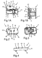
- Fig. 1A
- in schematischer und leicht perspektivischer Schnittdarstellung eine Bedienvorrichtung gemäß einer Ausführungsform der Erfindung;
- Fig. 1B
- in schematischer Darstellung eine Schnittansicht durch die Bedienvorrichtung gemäß
Fig. 1 A; - Fig. 2
- in schematischer und perspektivischer Darstellung die Bedienvorrichtung, wobei ein Bedienelement insgesamt drei Betätigungsflächen aufweist;
- Fig. 3
- in schematischer und leicht perspektivischer Darstellung die Bedienvorrichtung, wobei das Bedienelement transparent dargestellt ist;
- Fig. 4
- in schematischer Darstellung eine Seitenansicht der Bedienvorrichtung;
- Fig. 5
- in schematischer Darstellung eine Rückseite des Bedienelements, wobei ein Grundträger der Bedienvorrichtung transparent dargestellt ist;
- Fig. 6
- in schematischer Darstellung eine elastische Dichtung für die Bedienvorrichtung;
- Fig. 7
- in schematischer Darstellung die Bedienvorrichtung, wobei eine Betätigungsfläche des Bedienelements beziehungsweise ein daran angebrachtes Symbol in Überdeckung mit einem Schalter und einem Stößelelement angeordnet ist;
- Fig. 8
- in schematischer Darstellung die Bedienvorrichtung, wobei eine Betätigungsfläche beziehungsweise ein Symbol bezüglich eines Stößelelements und eines Schalters versetzt angeordnet ist; und
- Fig. 9
- in schematischer und leicht perspektivischer Darstellung die Rückseite des Bedienelements.
- In den Figuren werden gleiche und funktionsgleiche Elemente mit den gleichen Bezugszeichen versehen.
- Eine in den
Figuren 1A und 1B gezeigte Bedienvorrichtung 1 umfasst ein Bedienelement 2, ein Fluid 3, eine Dichtung 4, einen Grundträger 5, ein Stößelelement 6, wie auch eine Leiterplatte 7 (PCB) mit einem daran angebrachten elektrischen Schalter 8. - Der Schalter 8 kann beispielsweise ein Taster, eine Schaltmatte oder dergleichen sein. Der Schalter 8 ist ein haptisches Element; dies bedeutet, dass der Schalter 8 eine haptische Rückmeldung bei dessen Betätigung erzeugt. Der Schalter 8 kann beispielsweise mit einer Funktion in einem Fahrzeug verknüpft sein, so dass durch Betätigen des Schalters 8 die Funktion aktiviert beziehungsweise deaktiviert wird.
- Das Bedienelement 2 ist eine flache beziehungsweise dünne Blende und weist die Haubenform auf. Es weist eine flache Betätigungswand 9 auf, wie auch sich an die Betätigungswand 9 anschließende und mit der Betätigungswand 9 einen Winkel von 90° einschließende Seitenwände 10. Das Bedienelement 2 ist im Wesentlichen eigensteif. Es kann beispielsweise aus Kunststoff ausgebildet sein. Das Bedienelement 9 weist ferner im Ausführungsbeispiel drei flexible Betätigungsflächen auf, nämlich eine erste Betätigungsfläche 11, eine zweite Betätigungsfläche 12 und eine dritte Betätigungsfläche 13 (siehe beispielsweise
Fig. 2 ). Die Betätigungsflächen 11, 12, 13 können beispielsweise aus einem elastischen Material ausgebildet sein. Sie können aber auch ebenfalls wie das gesamte Bedienelement 2 aus einem dünnwandigen Kunststoff bereitgestellt und somit biegbar sein. Es erweist sich jedoch als besonders vorteilhaft, wenn die Betätigungsflächen 11, 12, 13 aus einem elastischen Material ausgebildet sind, während der restliche Teil des Bedienelements 2 aus eigensteifen Kunststoff bereitgestellt ist. - An den Betätigungsflächen 11, 12, 13 ist jeweils ein Symbol beziehungsweise ein Kennzeichen 14, 15, 16 angebracht, welches die jeweilige Funktion symbolisiert.
- Das Fluid 3, welches im Ausführungsbeispiel eine flüssiges Medium ist, befindet sich in einem Raum 17 zwischen der Betätigungswand 9 des Bedienelements 2 und der Dichtung 4. Wie in
Fig. 1B dargestellt ist, kann der Raum 17 zumindest teilweise durch eine an der Rückwand der Betätigungswand 9 ausgebildete Aussparung bzw. Vertiefung gebildet sein. Die Dichtung liegt bereichsweise an dem Grundträger 5 an. In dem Grundträger 5 ist eine Durchgangsöffnung ausgebildet, durch welche sich das Stößelelement 6 hindurch erstreckt. Das Stößelelement 6 liegt einerseits an der Dichtung 4, nämlich an einer vom Fluid 3 abgewandten Seite der Dichtung 4, und andererseits an dem elektrischen Schalter 8 an. Das Stößelelement 6 ist also in der Durchgangsöffnung verschiebbar gelagert. - Wird nun auf die Betätigungswand 9 - nämlich auf eine der Betätigungsflächen 11, 12, 13 - ein Betätigungsdruck durch eine Bedienperson ausgeübt, so wird dieser über das Fluid 3 auf das Stößelelement 6 übertragen, so dass selbiges den Schalter 8 betätigt. Der Betätigungsdruck wird also über das Fluid 3 und das Stößelelement 6 auf den Schalter 8 übertragen.
- In
Fig. 2 ist eine perspektivische Draufsicht auf die Bedienvorrichtung 1 dargestellt. Wie ausFig. 2 hervorgeht, weist das Bedienelement 2 im Ausführungsbeispiel insgesamt vier Befestigungselemente 18 auf (inFig. 2 sind lediglich zwei Befestigungselemente 18 dargestellt). Die Befestigungselemente 18 sind in Form von Ösen ausgebildet. InFig. 2 sind außerdem die Betätigungsflächen 11, 12, 13, wie auch die zugehörigen Symbole 14, 15, 16 dargestellt. - In
Fig. 3 ist das Bedienelement 2 transparent dargestellt. Zu jeder Betätigungsfläche 11, 12, 13 weist die Bedienvorrichtung 1 jeweils ein genanntes Fluid 3 auf, wie auch jeweils ein genanntes Stößelelement 6 und jeweils einen genannten elektrischen Schalter 8. Das Stößelelement 6 und der Schalter 8, welche der ersten Betätigungsfläche 11 zugeordnet sind, befinden sich unmittelbar unterhalb der Betätigungsfläche 11. Mit anderen Worten ist die Betätigungsfläche 11 in Überlappung mit dem zugehörigen Stößelelement 6 und dem zugehörigen Schalter 8 angeordnet. Hingegen sind die weiteren zwei Betätigungsflächen 12, 13 bezüglich der jeweiligen Stößelelemente 6 und der Schalter 8 versetzt angeordnet. Dabei ist das der Betätigungsfläche 12 zugeordnete Fluid 3 in einem Kanal 19 angeordnet, welcher die Betätigungsfläche 12 mit dem zugehörigen Stößelelement 6 verbindet. Entsprechend ist die Betätigungsfläche 13 über einen Kanal 20 mit dem zugehörigen Stößelelement 6 gekoppelt. In dem Kanal 20 befindet sich das der Betätigungsfläche 13 zugeordnete Fluid 3. - Die Kanäle 19, 20 - diese sind durch jeweils einen genannten Raum 17 zwischen der Betätigungswand 9 und der Dichtung 4 gebildet - erstrecken sich parallel zur Betätigungswand 9. Die Kanäle 19, 20 sind auch durch die Betätigungswand 9 unmittelbar begrenzt, wie auch durch die gemeinsame Dichtung 4. Die Kanäle 19, 20 können beispielsweise durch Aussparungen bzw. Vertiefungen gebildet sein, welche in der Betätigungswand 9 - nämlich an der Innenseite - ausgebildet sind.
- In
Fig. 4 ist eine Seitenansicht der Bedienvorrichtung 1 gezeigt. Wie ausFig. 4 hervorgeht, können die Betätigungsflächen 11, 12, 13 eine leicht gewölbte beziehungsweise ausgeprägte Form aufweisen. Alternativ können die Betätigungsflächen 11, 12, 13 auch gerade beziehungsweise flach sein, so dass die gesamte Betätigungswand 9 eine gerade und flache Wand ist. -
Fig. 5 zeigt eine Rückseite des Bedienelements 2. InFig. 5 ist der eigensteife und aus Kunststoff bereitgestellte Grundträger 5 transparent dargestellt, so dass die zwischen der Betätigungswand 9 und dem Grundträger 5 liegende Dichtung 4 sichtbar dargestellt ist. InFig. 5 sind außerdem die Stößelelemente 6 gezeigt. Der Grundträger 5 ist an der Rückseite der Betätigungswand 9 befestigt, nämlich an einer Vielzahl von Befestigungsstellen 21. Die Anbringung des Grundträgers 5 an der Rückseite kann beispielsweise durch Kaltverstemmen und/oder durch Heißverstemmen und/oder durch Verschrauben und/oder durch Verkleben und/oder durch Verschweißen mithilfe des Ultraschalls erfolgen. - In
Fig. 6 ist die für alle Betätigungsflächen 11, 12, 13, wie auch für alle Fluide 3 gemeinsame Dichtung 4 dargestellt. Die Dichtung 4 ist beispielsweise aus Gummi ausgebildet. Sie weist insgesamt drei Bereiche 22 auf, an welche die jeweiligen Stößelelemente 6 angrenzen. - Bezug nehmend auf
Fig. 7 wird nun die Betätigung der Betätigungsfläche 11 näher erläutert. Auf die Betätigungsfläche 11 wirkt eine Betätigungskraft, nämlich in Betätigungsrichtung 23. Die Betätigungsfläche 11 wird verformt und übt auf das Fluid 3 einen Betätigungsdruck aus. Dieser Betätigungsdruck wird über das Fluid 3 und über die Dichtung 4 auf das unterhalb der Betätigungsfläche 11 befindliche Stößelelement 6 übertragen. Auf diese Art und Weise wird das Stößelelement 6 bewegt und betätigt den Schalter 8. - Bezug nehmend auf
Fig. 8 wird die Betätigung der Betätigungsfläche 12 näher erläutert. Wie bereits ausgeführt, ist die Betätigungsfläche 12 über den Kanal 19 mit dem Stößelelement 6 gekoppelt. Wirkt nun eine Kraft auf die Betätigungsfläche 12, nämlich in Betätigungsrichtung 23, so wird der Betätigungsdruck über das Fluid 3 parallel zur Betätigungswand 9 - in Pfeilrichtung 24 - übertragen, nämlich hin zum Stößelelement 6. Die Richtung der Übertragung des Betätigungsdrucks ist durch die Form des Kanals 19 vorbestimmt. Wie ausFig. 8 hervorgeht, kann der Schalter 8, wie auch das Stößelelement 6, prinzipiell an beliebiger Stelle angeordnet sein. Dies ist durch das Fluid 3 ermöglicht, mittels welchem der Betätigungsdruck über quasi beliebige Strecken übertragen werden kann. - Die Rückseite des Bedienelements 2 ohne den Grundträger 5 und ohne die Dichtung 4 ist in
Fig. 9 dargestellt. Die Kanäle 19, 20 sind durch entsprechende Vertiefungen in der Rückseite der Betätigungswand 9 gebildet. Die Betätigungsflächen 11, 12, 13 können auch lichtdurchlässig sein, so dass die entsprechenden Symbole 14, 15, 16 von der Rückseite aus beleuchtet werden können. In diesem Falle kann das Fluid 3 ebenfalls lichtdurchlässig sein.
Claims (6)
- Bedienvorrichtung (1) für ein Fahrzeug, mit einem durch eine Bedienperson betätigbaren Bedienelement (2) und einem elektrischen Schalter (8), welcher abhängig von einer Betätigung des Bedienelements (2) betätigbar ist, und mit Übertragungsmitteln (3, 6) zum Übertragen eines Betätigungsdrucks von dem Bedienelement (2) auf den Schalter (8), wobei die Übertragungsmittel (3, 6) ein Fluid (3) zum Übertragen des Betätigungsdrucks umfassen, wobei die Bedienvorrichtung (1) einen Grundträger (5) aufweist und das Fluid (3) in einem zwischen dem Bedienelement (2) und dem Grundträger (5) ausgebildeten Raum (17) angeordnet ist, wobei die Bedienvorrichtung (1) eine Dichtung (4) aufweist, mittels welcher der Raum (17) abgedichtet ist und
sich die Dichtung (4) an den Grundträger (5) unmittelbar anschließt, so dass der Raum (17) unmittelbar durch die Dichtung (4) einerseits und durch das Bedienelement (2) andererseits begrenzt ist,
dadurch gekennzeichnet, dass
die Übertragungsmittel (3, 6) zusätzlich ein eigensteifes Stößelelement (6) umfassen, mittels welchem der Betätigungsdruck streckenweise von dem Bedienelement (2) auf den Schalter (8) übertragbar ist, wobei das Stößelelement (6) zwischen dem Fluid (3) und dem Schalter (8) angeordnet ist, einerseits an die Dichtung und andererseits an den elektrischen Schalter angrenzt.und unmittelbar an die an die von dem Fluid abgewandte und dem Grundträger zugewandte Seite der Dichtung anschließt, derart dass Stößelelement unter Vermittlung der Dichtung an dem Fluid abgestützt ist. - Bedienvorrichtung (1) nach Anspruch 1,
dadurch gekennzeichnet, dass
das Bedienelement (2) zumindest bereichsweise flexibel, insbesondere aus einem elastischen und/oder biegbaren Material, ausgebildet ist. - Bedienvorrichtung (1) nach Anspruch 1 oder 2,
dadurch gekennzeichnet, dass
das Fluid (3) unmittelbar an das Bedienelement (2) angrenzt. - Bedienvorrichtung (1) nach einem der vorhergehenden Ansprüche,
dadurch gekennzeichnet, dass
das Bedienelement (2) zumindest zwei flexible Betätigungsflächen (11, 12, 13) aufweist und die Bedienvorrichtung (1) für jede Betätigungsfläche (11, 12, 13) einen elektrischen Schalter (8) aufweist, wobei die Übertragungsmittel (3, 6) für jede Betätigungsfläche (11, 12, 13) jeweils ein Fluid (3) zum Übertragen des Betätigungsdrucks von der jeweiligen Betätigungsfläche (11, 12, 13) auf den zugeordneten Schalter (8) umfassen. - Bedienvorrichtung (1) nach einem der vorhergehenden Ansprüche,
dadurch gekennzeichnet, dass
das Fluid (3) derart bezüglich des Schalters (8) angeordnet ist, dass beim Betätigen des Bedienelements (2) der Druck durch das Fluid (3) hin zum Schalter (8) zumindest streckenweise in einer Richtung (24) übertragbar ist, die mit einer Betätigungsrichtung (23) einen Winkel größer als 0°, insbesondere einen Winkel von 90°, einschließt. - Bedienvorrichtung (1) nach einem der vorhergehenden Ansprüche,
dadurch gekennzeichnet, dass
das Bedienelement (2) mit einem Kennzeichen (14, 15, 16) versehen ist, welches bezüglich des Schalters (8) in einer Haupterstreckungsrichtung des Bedienelements (2) versetzt angeordnet ist.
Applications Claiming Priority (2)
| Application Number | Priority Date | Filing Date | Title |
|---|---|---|---|
| DE102010021966A DE102010021966A1 (de) | 2010-05-28 | 2010-05-28 | Bedienvorrichtung für ein Fahrzeug |
| PCT/EP2011/058445 WO2011147817A1 (de) | 2010-05-28 | 2011-05-24 | Bedienvorrichtung für ein fahrzeug |
Publications (2)
| Publication Number | Publication Date |
|---|---|
| EP2576268A1 EP2576268A1 (de) | 2013-04-10 |
| EP2576268B1 true EP2576268B1 (de) | 2015-11-25 |
Family
ID=44626569
Family Applications (1)
| Application Number | Title | Priority Date | Filing Date |
|---|---|---|---|
| EP11721053.4A Not-in-force EP2576268B1 (de) | 2010-05-28 | 2011-05-24 | Bedienvorrichtung für ein fahrzeug |
Country Status (3)
| Country | Link |
|---|---|
| EP (1) | EP2576268B1 (de) |
| DE (1) | DE102010021966A1 (de) |
| WO (1) | WO2011147817A1 (de) |
Families Citing this family (3)
| Publication number | Priority date | Publication date | Assignee | Title |
|---|---|---|---|---|
| DE102012021642A1 (de) | 2012-09-13 | 2014-03-13 | Valeo Schalter Und Sensoren Gmbh | Schiebe- und Druckschalter für ein Fahrzeug und Kraftfahrzeug |
| DE102021215041A1 (de) | 2021-12-27 | 2023-06-29 | Faurecia Innenraum Systeme Gmbh | Bedienelement und Verfahren zur Betätigung einer Fahrzeugfunktion sowie Verkleidungsteil und Fahrzeug umfassend das Bedienelement |
| CN116588001B (zh) * | 2023-05-05 | 2025-12-30 | 阿维塔科技(重庆)有限公司 | 开关系统、调节方法以及汽车开关组件 |
Citations (1)
| Publication number | Priority date | Publication date | Assignee | Title |
|---|---|---|---|---|
| US4300029A (en) * | 1980-01-09 | 1981-11-10 | W. H. Brady Co. | Remote membrane switch |
Family Cites Families (7)
| Publication number | Priority date | Publication date | Assignee | Title |
|---|---|---|---|---|
| US4679030A (en) * | 1982-04-30 | 1987-07-07 | Volnak William M | Chording keyboard for generating binary data |
| JPH01258325A (ja) | 1987-10-09 | 1989-10-16 | Mic Electron Co | タクトスイッチ |
| US20060139185A1 (en) * | 2002-03-29 | 2006-06-29 | Pierre Bonnat | Input device for a computer system that utilizes ambient light, and a method of manufacturing the same |
| DE10331284B4 (de) * | 2003-07-10 | 2005-06-16 | Gummi-Welz Gmbh & Co. Kg | Fußschutzleiste |
| CN101233592B (zh) | 2005-08-03 | 2010-12-08 | 普雷有限公司 | 用于汽车的控制元件 |
| EP2020666B1 (de) * | 2007-08-01 | 2013-11-06 | BlackBerry Limited | Tastengestaltung für eine kompakte Tastatur einer tragbaren Kommunikationsvorrichtung |
| CN201134365Y (zh) | 2007-11-02 | 2008-10-15 | 浙江开控电气有限公司 | 电气开关 |
-
2010
- 2010-05-28 DE DE102010021966A patent/DE102010021966A1/de not_active Withdrawn
-
2011
- 2011-05-24 WO PCT/EP2011/058445 patent/WO2011147817A1/de not_active Ceased
- 2011-05-24 EP EP11721053.4A patent/EP2576268B1/de not_active Not-in-force
Patent Citations (1)
| Publication number | Priority date | Publication date | Assignee | Title |
|---|---|---|---|---|
| US4300029A (en) * | 1980-01-09 | 1981-11-10 | W. H. Brady Co. | Remote membrane switch |
Also Published As
| Publication number | Publication date |
|---|---|
| EP2576268A1 (de) | 2013-04-10 |
| WO2011147817A1 (de) | 2011-12-01 |
| DE102010021966A1 (de) | 2011-12-01 |
Similar Documents
| Publication | Publication Date | Title |
|---|---|---|
| DE102012221107B3 (de) | Bedienvorrichtung für eine Fahrzeugkomponente | |
| DE602004010753T2 (de) | Tastatur mit versenkbaren Tasten und Taste einer solchen Tastatur besonders geeignet für das Armaturenbrett eines Fahrzeugs | |
| EP1859334B1 (de) | Berührungsempfindlicher bildschirm mit haptischer rückmeldung | |
| DE102017220780B3 (de) | Tastschalter und Kraftfahrzeug mit einem Tastschalter | |
| DE102009056186B4 (de) | Bedieneinrichtung in einem Kraftfahrzeug | |
| DE102008005256A1 (de) | Lenksäule mit Kunststoffgleithülse | |
| DE102014225569A1 (de) | Steuerknopfeinrichtung | |
| DE102007046999B3 (de) | Betätiger | |
| EP2576268B1 (de) | Bedienvorrichtung für ein fahrzeug | |
| DE102008036155A1 (de) | Bedientastenanordnung | |
| DE102021004934A1 (de) | Fahrzeugtürbetätigungselement | |
| DE102007054347B3 (de) | Manuell betätigbarer Schalter | |
| WO2012104289A2 (de) | Oberflächen integrierte schaltelementanordung | |
| DE102005013202A1 (de) | Lenkradschalter | |
| DE102017113662A1 (de) | Kraftfahrzeugbedienvorrichtung sowie Verfahren zum Herstellen einer Kraftfahrzeugbedienvorrichtung | |
| DE102007029021B4 (de) | Gassack-Einrichtung | |
| DE102005007887B3 (de) | Vorrichtung zur Betätigung einer Sanitärarmatur | |
| DE102017209268B4 (de) | Anzeigesystem | |
| DE102022109971B3 (de) | Bedieninterface eines Kraftfahrzeugs und Kraftfahrzeug | |
| EP2348638A2 (de) | Kapazitiver Berührungs- und/oder Annäherungsschalter | |
| DE102018105927A1 (de) | Berührungsempfindliches Bedienelement | |
| EP3934930B1 (de) | Schaltungsanordnung | |
| EP2065255A1 (de) | Lenkradhupe | |
| DE102008049796A1 (de) | Schaltanordnung für ein Schaltgetriebe | |
| DE102013202670A1 (de) | Luftleitvorrichtung für einen Heckbereich eines Kraftfahrzeugs |
Legal Events
| Date | Code | Title | Description |
|---|---|---|---|
| PUAI | Public reference made under article 153(3) epc to a published international application that has entered the european phase |
Free format text: ORIGINAL CODE: 0009012 |
|
| 17P | Request for examination filed |
Effective date: 20121113 |
|
| AK | Designated contracting states |
Kind code of ref document: A1 Designated state(s): AL AT BE BG CH CY CZ DE DK EE ES FI FR GB GR HR HU IE IS IT LI LT LU LV MC MK MT NL NO PL PT RO RS SE SI SK SM TR |
|
| DAX | Request for extension of the european patent (deleted) | ||
| 17Q | First examination report despatched |
Effective date: 20140731 |
|
| REG | Reference to a national code |
Ref country code: DE Ref legal event code: R079 Ref document number: 502011008413 Country of ref document: DE Free format text: PREVIOUS MAIN CLASS: B60K0037060000 Ipc: H01H0013706500 |
|
| GRAP | Despatch of communication of intention to grant a patent |
Free format text: ORIGINAL CODE: EPIDOSNIGR1 |
|
| RIC1 | Information provided on ipc code assigned before grant |
Ipc: H01H 13/7065 20060101AFI20150508BHEP |
|
| INTG | Intention to grant announced |
Effective date: 20150610 |
|
| GRAS | Grant fee paid |
Free format text: ORIGINAL CODE: EPIDOSNIGR3 |
|
| GRAA | (expected) grant |
Free format text: ORIGINAL CODE: 0009210 |
|
| AK | Designated contracting states |
Kind code of ref document: B1 Designated state(s): AL AT BE BG CH CY CZ DE DK EE ES FI FR GB GR HR HU IE IS IT LI LT LU LV MC MK MT NL NO PL PT RO RS SE SI SK SM TR |
|
| REG | Reference to a national code |
Ref country code: GB Ref legal event code: FG4D Free format text: NOT ENGLISH |
|
| REG | Reference to a national code |
Ref country code: CH Ref legal event code: EP |
|
| REG | Reference to a national code |
Ref country code: AT Ref legal event code: REF Ref document number: 762966 Country of ref document: AT Kind code of ref document: T Effective date: 20151215 |
|
| REG | Reference to a national code |
Ref country code: IE Ref legal event code: FG4D Free format text: LANGUAGE OF EP DOCUMENT: GERMAN |
|
| REG | Reference to a national code |
Ref country code: DE Ref legal event code: R096 Ref document number: 502011008413 Country of ref document: DE |
|
| REG | Reference to a national code |
Ref country code: LT Ref legal event code: MG4D |
|
| REG | Reference to a national code |
Ref country code: NL Ref legal event code: MP Effective date: 20160225 |
|
| PG25 | Lapsed in a contracting state [announced via postgrant information from national office to epo] |
Ref country code: LT Free format text: LAPSE BECAUSE OF FAILURE TO SUBMIT A TRANSLATION OF THE DESCRIPTION OR TO PAY THE FEE WITHIN THE PRESCRIBED TIME-LIMIT Effective date: 20151125 Ref country code: ES Free format text: LAPSE BECAUSE OF FAILURE TO SUBMIT A TRANSLATION OF THE DESCRIPTION OR TO PAY THE FEE WITHIN THE PRESCRIBED TIME-LIMIT Effective date: 20151125 Ref country code: HR Free format text: LAPSE BECAUSE OF FAILURE TO SUBMIT A TRANSLATION OF THE DESCRIPTION OR TO PAY THE FEE WITHIN THE PRESCRIBED TIME-LIMIT Effective date: 20151125 Ref country code: NO Free format text: LAPSE BECAUSE OF FAILURE TO SUBMIT A TRANSLATION OF THE DESCRIPTION OR TO PAY THE FEE WITHIN THE PRESCRIBED TIME-LIMIT Effective date: 20160225 Ref country code: IS Free format text: LAPSE BECAUSE OF FAILURE TO SUBMIT A TRANSLATION OF THE DESCRIPTION OR TO PAY THE FEE WITHIN THE PRESCRIBED TIME-LIMIT Effective date: 20160325 Ref country code: NL Free format text: LAPSE BECAUSE OF FAILURE TO SUBMIT A TRANSLATION OF THE DESCRIPTION OR TO PAY THE FEE WITHIN THE PRESCRIBED TIME-LIMIT Effective date: 20151125 |
|
| REG | Reference to a national code |
Ref country code: FR Ref legal event code: PLFP Year of fee payment: 6 |
|
| PG25 | Lapsed in a contracting state [announced via postgrant information from national office to epo] |
Ref country code: GR Free format text: LAPSE BECAUSE OF FAILURE TO SUBMIT A TRANSLATION OF THE DESCRIPTION OR TO PAY THE FEE WITHIN THE PRESCRIBED TIME-LIMIT Effective date: 20160226 Ref country code: SE Free format text: LAPSE BECAUSE OF FAILURE TO SUBMIT A TRANSLATION OF THE DESCRIPTION OR TO PAY THE FEE WITHIN THE PRESCRIBED TIME-LIMIT Effective date: 20151125 Ref country code: FI Free format text: LAPSE BECAUSE OF FAILURE TO SUBMIT A TRANSLATION OF THE DESCRIPTION OR TO PAY THE FEE WITHIN THE PRESCRIBED TIME-LIMIT Effective date: 20151125 Ref country code: LV Free format text: LAPSE BECAUSE OF FAILURE TO SUBMIT A TRANSLATION OF THE DESCRIPTION OR TO PAY THE FEE WITHIN THE PRESCRIBED TIME-LIMIT Effective date: 20151125 Ref country code: PT Free format text: LAPSE BECAUSE OF FAILURE TO SUBMIT A TRANSLATION OF THE DESCRIPTION OR TO PAY THE FEE WITHIN THE PRESCRIBED TIME-LIMIT Effective date: 20160325 Ref country code: RS Free format text: LAPSE BECAUSE OF FAILURE TO SUBMIT A TRANSLATION OF THE DESCRIPTION OR TO PAY THE FEE WITHIN THE PRESCRIBED TIME-LIMIT Effective date: 20151125 Ref country code: PL Free format text: LAPSE BECAUSE OF FAILURE TO SUBMIT A TRANSLATION OF THE DESCRIPTION OR TO PAY THE FEE WITHIN THE PRESCRIBED TIME-LIMIT Effective date: 20151125 |
|
| PG25 | Lapsed in a contracting state [announced via postgrant information from national office to epo] |
Ref country code: CZ Free format text: LAPSE BECAUSE OF FAILURE TO SUBMIT A TRANSLATION OF THE DESCRIPTION OR TO PAY THE FEE WITHIN THE PRESCRIBED TIME-LIMIT Effective date: 20151125 Ref country code: IT Free format text: LAPSE BECAUSE OF FAILURE TO SUBMIT A TRANSLATION OF THE DESCRIPTION OR TO PAY THE FEE WITHIN THE PRESCRIBED TIME-LIMIT Effective date: 20151125 |
|
| REG | Reference to a national code |
Ref country code: DE Ref legal event code: R097 Ref document number: 502011008413 Country of ref document: DE |
|
| PG25 | Lapsed in a contracting state [announced via postgrant information from national office to epo] |
Ref country code: DK Free format text: LAPSE BECAUSE OF FAILURE TO SUBMIT A TRANSLATION OF THE DESCRIPTION OR TO PAY THE FEE WITHIN THE PRESCRIBED TIME-LIMIT Effective date: 20151125 Ref country code: SK Free format text: LAPSE BECAUSE OF FAILURE TO SUBMIT A TRANSLATION OF THE DESCRIPTION OR TO PAY THE FEE WITHIN THE PRESCRIBED TIME-LIMIT Effective date: 20151125 Ref country code: EE Free format text: LAPSE BECAUSE OF FAILURE TO SUBMIT A TRANSLATION OF THE DESCRIPTION OR TO PAY THE FEE WITHIN THE PRESCRIBED TIME-LIMIT Effective date: 20151125 Ref country code: RO Free format text: LAPSE BECAUSE OF FAILURE TO SUBMIT A TRANSLATION OF THE DESCRIPTION OR TO PAY THE FEE WITHIN THE PRESCRIBED TIME-LIMIT Effective date: 20151125 Ref country code: SM Free format text: LAPSE BECAUSE OF FAILURE TO SUBMIT A TRANSLATION OF THE DESCRIPTION OR TO PAY THE FEE WITHIN THE PRESCRIBED TIME-LIMIT Effective date: 20151125 Ref country code: BE Free format text: LAPSE BECAUSE OF NON-PAYMENT OF DUE FEES Effective date: 20160531 |
|
| PLBE | No opposition filed within time limit |
Free format text: ORIGINAL CODE: 0009261 |
|
| STAA | Information on the status of an ep patent application or granted ep patent |
Free format text: STATUS: NO OPPOSITION FILED WITHIN TIME LIMIT |
|
| 26N | No opposition filed |
Effective date: 20160826 |
|
| PG25 | Lapsed in a contracting state [announced via postgrant information from national office to epo] |
Ref country code: SI Free format text: LAPSE BECAUSE OF FAILURE TO SUBMIT A TRANSLATION OF THE DESCRIPTION OR TO PAY THE FEE WITHIN THE PRESCRIBED TIME-LIMIT Effective date: 20151125 |
|
| PG25 | Lapsed in a contracting state [announced via postgrant information from national office to epo] |
Ref country code: LU Free format text: LAPSE BECAUSE OF FAILURE TO SUBMIT A TRANSLATION OF THE DESCRIPTION OR TO PAY THE FEE WITHIN THE PRESCRIBED TIME-LIMIT Effective date: 20160524 |
|
| REG | Reference to a national code |
Ref country code: CH Ref legal event code: PL |
|
| GBPC | Gb: european patent ceased through non-payment of renewal fee |
Effective date: 20160524 |
|
| PG25 | Lapsed in a contracting state [announced via postgrant information from national office to epo] |
Ref country code: LI Free format text: LAPSE BECAUSE OF NON-PAYMENT OF DUE FEES Effective date: 20160531 Ref country code: CH Free format text: LAPSE BECAUSE OF NON-PAYMENT OF DUE FEES Effective date: 20160531 |
|
| REG | Reference to a national code |
Ref country code: IE Ref legal event code: MM4A |
|
| REG | Reference to a national code |
Ref country code: FR Ref legal event code: PLFP Year of fee payment: 7 |
|
| PG25 | Lapsed in a contracting state [announced via postgrant information from national office to epo] |
Ref country code: IE Free format text: LAPSE BECAUSE OF NON-PAYMENT OF DUE FEES Effective date: 20160524 Ref country code: GB Free format text: LAPSE BECAUSE OF NON-PAYMENT OF DUE FEES Effective date: 20160524 |
|
| REG | Reference to a national code |
Ref country code: AT Ref legal event code: MM01 Ref document number: 762966 Country of ref document: AT Kind code of ref document: T Effective date: 20160524 |
|
| PG25 | Lapsed in a contracting state [announced via postgrant information from national office to epo] |
Ref country code: AT Free format text: LAPSE BECAUSE OF NON-PAYMENT OF DUE FEES Effective date: 20160524 |
|
| REG | Reference to a national code |
Ref country code: FR Ref legal event code: PLFP Year of fee payment: 8 |
|
| PG25 | Lapsed in a contracting state [announced via postgrant information from national office to epo] |
Ref country code: HU Free format text: LAPSE BECAUSE OF FAILURE TO SUBMIT A TRANSLATION OF THE DESCRIPTION OR TO PAY THE FEE WITHIN THE PRESCRIBED TIME-LIMIT; INVALID AB INITIO Effective date: 20110524 Ref country code: CY Free format text: LAPSE BECAUSE OF FAILURE TO SUBMIT A TRANSLATION OF THE DESCRIPTION OR TO PAY THE FEE WITHIN THE PRESCRIBED TIME-LIMIT Effective date: 20151125 |
|
| PG25 | Lapsed in a contracting state [announced via postgrant information from national office to epo] |
Ref country code: MK Free format text: LAPSE BECAUSE OF FAILURE TO SUBMIT A TRANSLATION OF THE DESCRIPTION OR TO PAY THE FEE WITHIN THE PRESCRIBED TIME-LIMIT Effective date: 20151125 Ref country code: TR Free format text: LAPSE BECAUSE OF FAILURE TO SUBMIT A TRANSLATION OF THE DESCRIPTION OR TO PAY THE FEE WITHIN THE PRESCRIBED TIME-LIMIT Effective date: 20151125 Ref country code: MC Free format text: LAPSE BECAUSE OF FAILURE TO SUBMIT A TRANSLATION OF THE DESCRIPTION OR TO PAY THE FEE WITHIN THE PRESCRIBED TIME-LIMIT Effective date: 20151125 Ref country code: MT Free format text: LAPSE BECAUSE OF FAILURE TO SUBMIT A TRANSLATION OF THE DESCRIPTION OR TO PAY THE FEE WITHIN THE PRESCRIBED TIME-LIMIT Effective date: 20151125 |
|
| PG25 | Lapsed in a contracting state [announced via postgrant information from national office to epo] |
Ref country code: BG Free format text: LAPSE BECAUSE OF FAILURE TO SUBMIT A TRANSLATION OF THE DESCRIPTION OR TO PAY THE FEE WITHIN THE PRESCRIBED TIME-LIMIT Effective date: 20151125 |
|
| PG25 | Lapsed in a contracting state [announced via postgrant information from national office to epo] |
Ref country code: AL Free format text: LAPSE BECAUSE OF FAILURE TO SUBMIT A TRANSLATION OF THE DESCRIPTION OR TO PAY THE FEE WITHIN THE PRESCRIBED TIME-LIMIT Effective date: 20151125 |
|
| P01 | Opt-out of the competence of the unified patent court (upc) registered |
Effective date: 20230528 |
|
| PGFP | Annual fee paid to national office [announced via postgrant information from national office to epo] |
Ref country code: DE Payment date: 20240513 Year of fee payment: 14 |
|
| PGFP | Annual fee paid to national office [announced via postgrant information from national office to epo] |
Ref country code: FR Payment date: 20240524 Year of fee payment: 14 |
|
| REG | Reference to a national code |
Ref country code: DE Ref legal event code: R119 Ref document number: 502011008413 Country of ref document: DE |
|
| PG25 | Lapsed in a contracting state [announced via postgrant information from national office to epo] |
Ref country code: DE Free format text: LAPSE BECAUSE OF NON-PAYMENT OF DUE FEES Effective date: 20251202 |
|
| PG25 | Lapsed in a contracting state [announced via postgrant information from national office to epo] |
Ref country code: FR Free format text: LAPSE BECAUSE OF NON-PAYMENT OF DUE FEES Effective date: 20250531 |