EP2576355B1 - Appareil de scellage de sac et unité de scellage - Google Patents
Appareil de scellage de sac et unité de scellage Download PDFInfo
- Publication number
- EP2576355B1 EP2576355B1 EP11731098.7A EP11731098A EP2576355B1 EP 2576355 B1 EP2576355 B1 EP 2576355B1 EP 11731098 A EP11731098 A EP 11731098A EP 2576355 B1 EP2576355 B1 EP 2576355B1
- Authority
- EP
- European Patent Office
- Prior art keywords
- sealing
- pair
- sealer
- apt
- gears
- Prior art date
- Legal status (The legal status is an assumption and is not a legal conclusion. Google has not performed a legal analysis and makes no representation as to the accuracy of the status listed.)
- Not-in-force
Links
- 238000007789 sealing Methods 0.000 title claims description 109
- 239000002699 waste material Substances 0.000 claims description 20
- 230000000284 resting effect Effects 0.000 claims description 7
- 239000004033 plastic Substances 0.000 claims description 5
- 239000002184 metal Substances 0.000 claims description 3
- 239000000463 material Substances 0.000 claims description 2
- 230000001360 synchronised effect Effects 0.000 claims description 2
- 230000008901 benefit Effects 0.000 description 4
- 238000000034 method Methods 0.000 description 4
- 229910001006 Constantan Inorganic materials 0.000 description 2
- 239000010815 organic waste Substances 0.000 description 2
- 238000010408 sweeping Methods 0.000 description 2
- 229920006362 Teflon® Polymers 0.000 description 1
- 230000004913 activation Effects 0.000 description 1
- 239000011248 coating agent Substances 0.000 description 1
- 238000000576 coating method Methods 0.000 description 1
- 125000004122 cyclic group Chemical group 0.000 description 1
- 230000001419 dependent effect Effects 0.000 description 1
- 230000000694 effects Effects 0.000 description 1
- 238000005516 engineering process Methods 0.000 description 1
- 230000005484 gravity Effects 0.000 description 1
- 230000002427 irreversible effect Effects 0.000 description 1
- 239000000155 melt Substances 0.000 description 1
- 230000002093 peripheral effect Effects 0.000 description 1
- 230000001681 protective effect Effects 0.000 description 1
- 230000001105 regulatory effect Effects 0.000 description 1
- 230000035943 smell Effects 0.000 description 1
Images


Classifications
-
- B—PERFORMING OPERATIONS; TRANSPORTING
- B65—CONVEYING; PACKING; STORING; HANDLING THIN OR FILAMENTARY MATERIAL
- B65B—MACHINES, APPARATUS OR DEVICES FOR, OR METHODS OF, PACKAGING ARTICLES OR MATERIALS; UNPACKING
- B65B51/00—Devices for, or methods of, sealing or securing package folds or closures; Devices for gathering or twisting wrappers, or necks of bags
- B65B51/10—Applying or generating heat or pressure or combinations thereof
- B65B51/14—Applying or generating heat or pressure or combinations thereof by reciprocating or oscillating members
- B65B51/146—Closing bags
-
- B—PERFORMING OPERATIONS; TRANSPORTING
- B29—WORKING OF PLASTICS; WORKING OF SUBSTANCES IN A PLASTIC STATE IN GENERAL
- B29C—SHAPING OR JOINING OF PLASTICS; SHAPING OF MATERIAL IN A PLASTIC STATE, NOT OTHERWISE PROVIDED FOR; AFTER-TREATMENT OF THE SHAPED PRODUCTS, e.g. REPAIRING
- B29C65/00—Joining or sealing of preformed parts, e.g. welding of plastics materials; Apparatus therefor
- B29C65/02—Joining or sealing of preformed parts, e.g. welding of plastics materials; Apparatus therefor by heating, with or without pressure
- B29C65/18—Joining or sealing of preformed parts, e.g. welding of plastics materials; Apparatus therefor by heating, with or without pressure using heated tools
- B29C65/22—Heated wire resistive ribbon, resistive band or resistive strip
- B29C65/221—Heated wire resistive ribbon, resistive band or resistive strip characterised by the type of heated wire, resistive ribbon, band or strip
- B29C65/222—Heated wire resistive ribbon, resistive band or resistive strip characterised by the type of heated wire, resistive ribbon, band or strip comprising at least a single heated wire
- B29C65/223—Heated wire resistive ribbon, resistive band or resistive strip characterised by the type of heated wire, resistive ribbon, band or strip comprising at least a single heated wire comprising several heated wires
-
- B—PERFORMING OPERATIONS; TRANSPORTING
- B29—WORKING OF PLASTICS; WORKING OF SUBSTANCES IN A PLASTIC STATE IN GENERAL
- B29C—SHAPING OR JOINING OF PLASTICS; SHAPING OF MATERIAL IN A PLASTIC STATE, NOT OTHERWISE PROVIDED FOR; AFTER-TREATMENT OF THE SHAPED PRODUCTS, e.g. REPAIRING
- B29C65/00—Joining or sealing of preformed parts, e.g. welding of plastics materials; Apparatus therefor
- B29C65/02—Joining or sealing of preformed parts, e.g. welding of plastics materials; Apparatus therefor by heating, with or without pressure
- B29C65/18—Joining or sealing of preformed parts, e.g. welding of plastics materials; Apparatus therefor by heating, with or without pressure using heated tools
- B29C65/22—Heated wire resistive ribbon, resistive band or resistive strip
- B29C65/221—Heated wire resistive ribbon, resistive band or resistive strip characterised by the type of heated wire, resistive ribbon, band or strip
- B29C65/224—Heated wire resistive ribbon, resistive band or resistive strip characterised by the type of heated wire, resistive ribbon, band or strip being a resistive ribbon, a resistive band or a resistive strip
-
- B—PERFORMING OPERATIONS; TRANSPORTING
- B29—WORKING OF PLASTICS; WORKING OF SUBSTANCES IN A PLASTIC STATE IN GENERAL
- B29C—SHAPING OR JOINING OF PLASTICS; SHAPING OF MATERIAL IN A PLASTIC STATE, NOT OTHERWISE PROVIDED FOR; AFTER-TREATMENT OF THE SHAPED PRODUCTS, e.g. REPAIRING
- B29C65/00—Joining or sealing of preformed parts, e.g. welding of plastics materials; Apparatus therefor
- B29C65/74—Joining or sealing of preformed parts, e.g. welding of plastics materials; Apparatus therefor by welding and severing, or by joining and severing, the severing being performed in the area to be joined, next to the area to be joined, in the joint area or next to the joint area
- B29C65/745—Joining or sealing of preformed parts, e.g. welding of plastics materials; Apparatus therefor by welding and severing, or by joining and severing, the severing being performed in the area to be joined, next to the area to be joined, in the joint area or next to the joint area using a single unit having both a severing tool and a welding tool
-
- B—PERFORMING OPERATIONS; TRANSPORTING
- B29—WORKING OF PLASTICS; WORKING OF SUBSTANCES IN A PLASTIC STATE IN GENERAL
- B29C—SHAPING OR JOINING OF PLASTICS; SHAPING OF MATERIAL IN A PLASTIC STATE, NOT OTHERWISE PROVIDED FOR; AFTER-TREATMENT OF THE SHAPED PRODUCTS, e.g. REPAIRING
- B29C66/00—General aspects of processes or apparatus for joining preformed parts
- B29C66/01—General aspects dealing with the joint area or with the area to be joined
- B29C66/05—Particular design of joint configurations
- B29C66/10—Particular design of joint configurations particular design of the joint cross-sections
- B29C66/11—Joint cross-sections comprising a single joint-segment, i.e. one of the parts to be joined comprising a single joint-segment in the joint cross-section
- B29C66/112—Single lapped joints
- B29C66/1122—Single lap to lap joints, i.e. overlap joints
-
- B—PERFORMING OPERATIONS; TRANSPORTING
- B29—WORKING OF PLASTICS; WORKING OF SUBSTANCES IN A PLASTIC STATE IN GENERAL
- B29C—SHAPING OR JOINING OF PLASTICS; SHAPING OF MATERIAL IN A PLASTIC STATE, NOT OTHERWISE PROVIDED FOR; AFTER-TREATMENT OF THE SHAPED PRODUCTS, e.g. REPAIRING
- B29C66/00—General aspects of processes or apparatus for joining preformed parts
- B29C66/40—General aspects of joining substantially flat articles, e.g. plates, sheets or web-like materials; Making flat seams in tubular or hollow articles; Joining single elements to substantially flat surfaces
- B29C66/41—Joining substantially flat articles ; Making flat seams in tubular or hollow articles
- B29C66/43—Joining a relatively small portion of the surface of said articles
- B29C66/431—Joining the articles to themselves
- B29C66/4312—Joining the articles to themselves for making flat seams in tubular or hollow articles, e.g. transversal seams
- B29C66/43121—Closing the ends of tubular or hollow single articles, e.g. closing the ends of bags
-
- B—PERFORMING OPERATIONS; TRANSPORTING
- B29—WORKING OF PLASTICS; WORKING OF SUBSTANCES IN A PLASTIC STATE IN GENERAL
- B29C—SHAPING OR JOINING OF PLASTICS; SHAPING OF MATERIAL IN A PLASTIC STATE, NOT OTHERWISE PROVIDED FOR; AFTER-TREATMENT OF THE SHAPED PRODUCTS, e.g. REPAIRING
- B29C66/00—General aspects of processes or apparatus for joining preformed parts
- B29C66/80—General aspects of machine operations or constructions and parts thereof
- B29C66/82—Pressure application arrangements, e.g. transmission or actuating mechanisms for joining tools or clamps
- B29C66/822—Transmission mechanisms
- B29C66/8221—Scissor or lever mechanisms, i.e. involving a pivot point
-
- B—PERFORMING OPERATIONS; TRANSPORTING
- B29—WORKING OF PLASTICS; WORKING OF SUBSTANCES IN A PLASTIC STATE IN GENERAL
- B29C—SHAPING OR JOINING OF PLASTICS; SHAPING OF MATERIAL IN A PLASTIC STATE, NOT OTHERWISE PROVIDED FOR; AFTER-TREATMENT OF THE SHAPED PRODUCTS, e.g. REPAIRING
- B29C66/00—General aspects of processes or apparatus for joining preformed parts
- B29C66/80—General aspects of machine operations or constructions and parts thereof
- B29C66/82—Pressure application arrangements, e.g. transmission or actuating mechanisms for joining tools or clamps
- B29C66/822—Transmission mechanisms
- B29C66/8222—Pinion or rack mechanisms
-
- B—PERFORMING OPERATIONS; TRANSPORTING
- B29—WORKING OF PLASTICS; WORKING OF SUBSTANCES IN A PLASTIC STATE IN GENERAL
- B29C—SHAPING OR JOINING OF PLASTICS; SHAPING OF MATERIAL IN A PLASTIC STATE, NOT OTHERWISE PROVIDED FOR; AFTER-TREATMENT OF THE SHAPED PRODUCTS, e.g. REPAIRING
- B29C66/00—General aspects of processes or apparatus for joining preformed parts
- B29C66/80—General aspects of machine operations or constructions and parts thereof
- B29C66/83—General aspects of machine operations or constructions and parts thereof characterised by the movement of the joining or pressing tools
- B29C66/834—General aspects of machine operations or constructions and parts thereof characterised by the movement of the joining or pressing tools moving with the parts to be joined
- B29C66/8351—Jaws mounted on rollers, cylinders, drums, bands, belts or chains; Flying jaws
- B29C66/83511—Jaws mounted on rollers, cylinders, drums, bands, belts or chains; Flying jaws jaws mounted on rollers, cylinders or drums
- B29C66/83513—Jaws mounted on rollers, cylinders, drums, bands, belts or chains; Flying jaws jaws mounted on rollers, cylinders or drums cooperating jaws mounted on rollers, cylinders or drums and moving in a closed path
-
- B—PERFORMING OPERATIONS; TRANSPORTING
- B29—WORKING OF PLASTICS; WORKING OF SUBSTANCES IN A PLASTIC STATE IN GENERAL
- B29C—SHAPING OR JOINING OF PLASTICS; SHAPING OF MATERIAL IN A PLASTIC STATE, NOT OTHERWISE PROVIDED FOR; AFTER-TREATMENT OF THE SHAPED PRODUCTS, e.g. REPAIRING
- B29C66/00—General aspects of processes or apparatus for joining preformed parts
- B29C66/80—General aspects of machine operations or constructions and parts thereof
- B29C66/84—Specific machine types or machines suitable for specific applications
- B29C66/849—Packaging machines
-
- B—PERFORMING OPERATIONS; TRANSPORTING
- B65—CONVEYING; PACKING; STORING; HANDLING THIN OR FILAMENTARY MATERIAL
- B65B—MACHINES, APPARATUS OR DEVICES FOR, OR METHODS OF, PACKAGING ARTICLES OR MATERIALS; UNPACKING
- B65B51/00—Devices for, or methods of, sealing or securing package folds or closures; Devices for gathering or twisting wrappers, or necks of bags
- B65B51/10—Applying or generating heat or pressure or combinations thereof
- B65B51/26—Devices specially adapted for producing transverse or longitudinal seams in webs or tubes
- B65B51/30—Devices, e.g. jaws, for applying pressure and heat, e.g. for subdividing filled tubes
- B65B51/306—Counter-rotating devices
-
- B—PERFORMING OPERATIONS; TRANSPORTING
- B29—WORKING OF PLASTICS; WORKING OF SUBSTANCES IN A PLASTIC STATE IN GENERAL
- B29C—SHAPING OR JOINING OF PLASTICS; SHAPING OF MATERIAL IN A PLASTIC STATE, NOT OTHERWISE PROVIDED FOR; AFTER-TREATMENT OF THE SHAPED PRODUCTS, e.g. REPAIRING
- B29C65/00—Joining or sealing of preformed parts, e.g. welding of plastics materials; Apparatus therefor
- B29C65/02—Joining or sealing of preformed parts, e.g. welding of plastics materials; Apparatus therefor by heating, with or without pressure
- B29C65/18—Joining or sealing of preformed parts, e.g. welding of plastics materials; Apparatus therefor by heating, with or without pressure using heated tools
- B29C65/22—Heated wire resistive ribbon, resistive band or resistive strip
- B29C65/228—Heated wire resistive ribbon, resistive band or resistive strip characterised by the means for electrically connecting the ends of said heated wire, resistive ribbon, resistive band or resistive strip
-
- B—PERFORMING OPERATIONS; TRANSPORTING
- B29—WORKING OF PLASTICS; WORKING OF SUBSTANCES IN A PLASTIC STATE IN GENERAL
- B29C—SHAPING OR JOINING OF PLASTICS; SHAPING OF MATERIAL IN A PLASTIC STATE, NOT OTHERWISE PROVIDED FOR; AFTER-TREATMENT OF THE SHAPED PRODUCTS, e.g. REPAIRING
- B29C66/00—General aspects of processes or apparatus for joining preformed parts
- B29C66/004—Preventing sticking together, e.g. of some areas of the parts to be joined
- B29C66/0042—Preventing sticking together, e.g. of some areas of the parts to be joined of the joining tool and the parts to be joined
-
- B—PERFORMING OPERATIONS; TRANSPORTING
- B29—WORKING OF PLASTICS; WORKING OF SUBSTANCES IN A PLASTIC STATE IN GENERAL
- B29L—INDEXING SCHEME ASSOCIATED WITH SUBCLASS B29C, RELATING TO PARTICULAR ARTICLES
- B29L2031/00—Other particular articles
- B29L2031/712—Containers; Packaging elements or accessories, Packages
- B29L2031/7128—Bags, sacks, sachets
-
- B—PERFORMING OPERATIONS; TRANSPORTING
- B65—CONVEYING; PACKING; STORING; HANDLING THIN OR FILAMENTARY MATERIAL
- B65F—GATHERING OR REMOVAL OF DOMESTIC OR LIKE REFUSE
- B65F2210/00—Equipment of refuse receptacles
- B65F2210/167—Sealing means
Definitions
- the present invention relates to a bag sealer and to a sealing unit comprising a bag sealer, conceived in particular for operating cyclically and in an automatic manner the sealing of waste collection bags.
- the sealing of collection bags is particularly useful as the irreversible closing of such a bag prevents the spreading of bad smells, ensures that there be no accidental leak of waste (something that cannot be guaranteed when the bags are closed by traditional methods), and moreover facilitates transport operations.
- manually driven bag-sealing apparatuses are known, usually associated to a suction system generating vacuum in the same bags concomitantly to the closing; said apparatuses usually comprise a sealing clamp consisting of a pair of members opposable to each other by a motion lying on a common plane, between which the bag to be sealed is interposed.
- the former is sealed, and therefore irreversibly closed, by closing the clamp, as the sealing members comprise a high-temperature surface that melts the edges of the same bag therebetween.
- a bag sealer according to the preamble of claim 1 is known from document US 2 695 150 .
- Object of the present invention is to solve the above-mentioned drawbacks by providing a sealer as defined in claim 1.
- a further object of the present invention is to provide a sealing unit as defined in claim 8.
- the present invention by overcoming the mentioned problems of the known art, entails several evident advantages.
- the sealer according to the present invention in particular when arranged inside a sealing unit placed downstream of a waste grinder, is capable, as will be described in detail hereinafter in connection to a preferred embodiment thereof given herein by way of example and not for limitative purposes, of operating in a totally automatic way the sealing of the (waste-containing) bag and its automatic ejection from the unit itself once sealed.
- the automatic sealing occurs in a manner such as to make this operation cyclic, nearly totally eliminating manual interventions.
- the sealing unit subject-matter of the present invention it is possible to arrange a bag, downstream of the grinder or more generally in a position such as to collect waste, and benefit from several filling / sealing / ejecting cycles with no need to worry about intervening every time a cycle has been completed.
- the sealer 1 comprises a pair of sealing members 21, 22 which are driven by a system 3 giving them an approaching/moving away motion, as will be described in detail hereinafter.
- the pair of sealing members 21 and 22 are apt to assume a first working configuration in which they cooperate with each other to seal a bag interposed therebetween (not depicted), preferably dedicated to waste collection, and a second resting configuration.
- the bag is preferably of biodegradable type, so as to be disposed of together with its content.
- the two sealing members 21 and 22 are depicted in a position intermediate between the two configurations mentioned above.
- the driving system 3 is apt to give the approaching/moving away motion so as to make the sealing members 21 and 22 assume respectively the working and resting configurations.
- the sealing members 21 and 22 during their motion sweep a pair of surfaces defining therebetween a convex space region.
- a box-type body 4 is also shown, in phantom lines, which is apt to house therein the sealer 1 so as to constitute a sealing unit as will be described in detail below.
- the sealing members 21, 22 are sealing rods which define, when in a working configuration, a sealing line at which they are substantially set in contact while sealing the bag (not shown) interposed therebetween.
- the driving system 3 comprises for each sealing rod 21 and 22 respectively a first 31, 32 and a second 33, 34 pair of gears, each pair of gears being connected therebetween by a tie member, onto which the respective sealing rod is integrally positioned.
- the first pair of gears 31, 32 comprises a driving gear 32, set in rotation by a driving pinion 51 in turn driven by a motor 5, preferably of electric type. Then, the driving pinion 51 acts on the driving gear 32, which drags the gear 31 by their connection, made just by the respective tie member.
- the two pairs of gears 31, 32 and 33, 34 advantageously cooperate therebetween in a manner such that the rotation taken by the first pair by means of the pinion 51 transmits motion to the second pair 33, 34, giving to the rods 21 and 22 a synchronous motion.
- Each of the sealing rods sweeps a respective curved surface during the dragging motion of the respective pair of gears. Therefore, the convex space region defined therebetween has a cusp at the sealing line.
- the gears of the first and second pair are preferably of sector type, and have an extension of about one quarter of circumference, or the gear extension needed to carry out the motion of the sealing rods, as will be better described hereinafter.
- the first pair of gears 32, 31 is shown, in which the driving gear 32, set in rotation by the pinion 51, has a toothed periphery comprising a first portion 321 apt to cooperate just with the pinion 51, and a second portion 322, adjacent to the first portion 321, and apt to cooperate with the driven gear opposed thereto, of the second pair of gears (not shown).
- the pinion 51 does not interfere with the driven gear, thereby making a drive chain which finally drives the sealing rods (of which only rod 21 is shown in the picture).
- the sealer 1 subject-matter of the present invention is shown in a side view.
- the driving pinion 51 can be seen, positioned along the first portion of the toothed periphery of the driving gear 32.
- the latter being rotatably connected at a center 323 thereof to an external frame, which in the case described herein is the above-introduced box-type body 4, is set in rotation about its center and, by cooperating with the driven gear 34 thanks to their toothed profiles, causes the approaching/moving away of the sealing rods (not shown in the figures) thereby sweeping surfaces shaped like arcs of circumference.
- the sealing rod 22 comprises, on a working surface thereof at which bag sealing occurs, a support 221 of plastic material on which a sealing resistor 222, preferably made of constantan is obtained, power-supplied by a metal core inside the plastic support 221.
- the sealing rod 22 comprises a first resistor 223, apt to operate a sealing at the bag portion lying along the sealing line, comprising waste therein.
- the resistor 223, being preferably obtained in a bottom portion of the sealing rod 22, is the first to come in contact with the bag during the approaching motion of the sealing rods.
- the rod 22 comprises cutting means 2221 centrally positioned thereon, which is apt to detach the bag portion comprising the waste (sealed by the resistor 223 introduced above), from the consecutive top portion of bag to be filled in a next discharge cycle.
- the sealing rod 22 comprises a second resistor 224, obtained topwise along the sealing rod 22, which operates the sealing of a bottom base of the new bag, just to enable to fill it in the next cycle.
- the cutting means 2221 is interposed between the first resistor 223 and the second resistor 224 and spaced therefrom, in a manner such as to enable the carrying out in sequence of the above-mentioned operations.
- said means comprises a third resistor 2221.
- the heat dissipated by said resistor 2221 is such as to act on the bag portion already sealed by the first resistor 223, thereby obtaining detachment of the bag bottom portion, comprising waste, from the top portion (yet to be filled).
- the resistors 2221, 223 and 224 are preferably made of constantan, and power-supplied by a metal core housed inside the plastic support 221.
- the rod 22 preferably comprises an outer coating of Teflon®, which advantageously ensures an effective sealing, preventing however the bag from getting stuck to the sealing resistor.
- the opposite sealing rod 21 preferably comprises only a respective plastic support 211, which anyhow proved sufficient to afford an opposing area to the sealing rod 22 needed for the above-described sealing operations.
- the collection bags will preferably be provided having a length such as to allow plural waste collection cycles.
- the bag is completely rolled up along an edge thereof, and begins to receive waste in its interior, so that the weight thereof causes its deployment inside the sealer.
- the gears activate an apparatus regulating the temperature of the sealing resistor.
- the apparatus is designed so that the resistor may reach an optimum temperature for carrying out the sealing just when the rods get in the working configuration. Referring to next Figures 5 and 6 , it is shown the sealer 1 when the rods 21 and 22 are in a working configuration.
- the rods are opposed therebetween so as to seal a bag interposed therebetween (not shown) and define, as highlighted above, a sealing line placed at the cusp, formed by the surfaces shaped like arcs of circumference swept thereby, during their approaching motion, at their tangency line.
- FIG. 7 the sealer 1 subject-matter of the present invention is shown when in a resting configuration. As may be seen, in such a configuration the sealing rods 21 and 22 are spaced in order to receive therebetween the bag to be sealed.
- a sealing unit 100 is shown, it also subject-matter of the present invention, conceived in particular for the sealing of organic waste collection bags.
- the unit 100 comprises the above-introduced box-type body 4, housing therein the above-described sealer 1 and defining a top inlet compartment 101, through which the collection bag is introduced, and a bottom base 102 for containing the bag during a filling thereof and ejecting the same following the sealing by activation of the sealer 1.
- the sealer 1 is positioned inside the box-type body 4 in a manner such that the convex space region faces onto the inlet compartment 101.
- the unit 100 is preferably placed downstream of a grinder (not shown) which grinds organic waste and fills the bag placed substantially near to the inlet compartment 101 of the unit 100.
- the bag is preferably rolled up along a peripheral edge thereof, and is unrolled by effect of gravity, owing to the weight of waste gradually collected therein, thus engaging the inside of the box-type body 4, thereby positioning itself between the sealing rods 21 and 22 of the sealer 1.
- the bag is preferably provided with a length such as to allow plural waste collection cycles, according to what has been described above with regard to the sealing rods.
- the sealing unit 100 is preferably prearranged with a system of sensors which are apt to activate the motor 5 for driving the sealing rods so as to give thereto an approaching motion, to reach the working configuration and seal the bag, when a predefined amount of waste is reached therein.
- a manual control could advantageously be prearranged, such as a button arranged on a push-button panel obtained on the sealing unit; its actuation will control the starting of the system of gears and therefore the driving of the sealing rods.
- the sealing rods 21 and 22 are capable of cooperating with the bag, still rolled up, near the inlet compartment 101, in order to prearrange the same bag for a successive cycle, by unrolling an initial portion thereof, so as to make the operations of sealing the bag and cyclically ejecting it from the body 4 very efficient, and completely eliminating the need of human intervention.
- the peculiar arc-like path followed by the sealing rods which start from a position substantially at the inlet compartment 101 and proceed to the base 102 of the unit, causes them to be provided with a motion having a component along the vertical; thus, the sealing process is substantially improved, as any waste leaks during the closing and sealing process are prevented just by the rods 21 and 22.
- the pairs of gears 31, 32 and 33, 34 are preferably located externally to the box-type body 4.
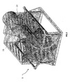
- the sealing unit 100 subject-matter of the present invention is again shown in a perspective view.
- the base 102 for containing/ejecting the collection bag is now evident.
- the unit 100 preferably comprises an automatic system for opening/closing the base 102, associated to the sealing rods 21 and 22, so as to automatically eject the collection bag once it has been filled with a predefined amount of waste and then sealed.
- the bottom base 102 comprises a pair of doors 1021 and 1022, which can be opened toward the outside of the box-type body 4.
- the automatic system for opening/closing comprises a pair of substantially L-shaped opposing members 10211, 10221 each obtained on a respective door 1021, 1022. Moreover, the automatic system comprises a pair of opposing members 341 and 371, each integral respectively to the sealing rod 22 and 21.
- the opposing members 341 and 371 comprise each a connection bar 341 and 371 connecting respectively the pairs of gears 33, 34 and 32, 31 obtained eccentrically with respect thereto.
- each approaching motion of the sealing rods drives the respective bar against the L-shaped opposing member obtained on each door, thereby carrying out the opening of the bottom base for ejection of the bag after the latter has been sealed.
- the sealing rods in order to cause a complete opening of the base 102, are moved away from each other, proceeding in the same direction of their approaching motion, thereby exceeding the working configuration and moving away from each other to allow the falling of the sealed bag.
- the return of the sealing rods in a resting configuration implying the reversing of the direction of rotation of the gears, entails the moving away of each bar from the related L-shaped member and therefore the closing of the bottom base, so as to restart a new filling cycle for a new bag.
- the gears are obtained on the outside of the box-type body 4, they are connected to the sealing rods by round slots 50 obtained on the same box-type body.
- FIG. 10 a section of the sealing unit 100 according to the invention is shown, in which the slots 50 inside which the sealing rods 21 and 22, driven by the gears (hatched in the figure), slide, are evident.
Landscapes
- Engineering & Computer Science (AREA)
- Mechanical Engineering (AREA)
- Package Closures (AREA)
Claims (12)
- Dispositif de scellement de sac (1) comprenant :• une paire d'éléments de scellement (21, 22) appropriés pour adopter une première configuration de travail dans laquelle ils coopèrent pour sceller un sac de collecte de déchets intercalé entre eux, et une seconde configuration de repos ;• un système (3) pour entraîner ladite paire d'éléments de scellement (21, 22) appropriés pour donner auxdits éléments de scellement (21, 22) un mouvement d'approche/d'éloignement afin de leur faire prendre lesdites configurations de travail/repos ;
dans lequel lesdits éléments de scellement (21, 22) sont appropriés pour balayer, pendant ledit mouvement, une paire de surfaces définissant entre elles une région d'espace convexe, ladite région d'espace convexe définie entre elles ayant une cuspide au niveau de la ligne de scellement dans ladite première configuration de travail, ladite paire d'éléments de scellement (21, 22) comprenant une première (21) et une seconde (22) tige de scellement, lesdites tiges (21, 22), lorsqu'elles sont dans une configuration de travail, étant aptes à définir une ligne de scellement au niveau d'une zone de tangence de ladite paire de surfaces balayées, lesdites surfaces étant incurvées, dans lequel lesdites surfaces balayées par lesdites tiges de scellement (21, 22) définissent une cuspide le long de ladite ligne de scellement, dans lequel ledit système d'entraînement (3) comprend une première (31, 32) et une seconde (33, 34) paire d'engrenages supportant respectivement ladite première (21) et ladite seconde (22) tige de scellement, chaque paire d'engrenages (31, 32 ; 33, 34) étant raccordée par un élément de lien sur lequel la tige de scellement (21, 22) respective est positionnée intégralement, caractérisé en ce que ledit système d'entraînement (3) comprend un pignon d'entraînement (51) approprié pour régler en rotation un engrenage d'entraînement (32) de ladite première paire d'engrenages (31, 32), ledit engrenage d'entraînement (32) ayant une périphérie dentée comprenant une première partie (321) appropriée pour coopérer avec ledit pignon d'entraînement (51), et une seconde partie (322) adjacente à ladite première partie (321) appropriée pour coopérer avec un engrenage entraîné (34) correspondant de ladite seconde paire d'engrenages (33, 34). - Dispositif de scellement (1) selon la revendication précédente, dans lequel lesdites paires d'engrenages (31, 32 ; 33, 34) sont appropriées pour coopérer entre elles afin de donner à ladite première (21) et à la seconde (22) tige de scellement, un mouvement synchrone le long de trajectoires respectives formées comme des arcs de circonférence.
- Dispositif de scellement (1) selon l'une quelconque des revendications précédentes, dans lequel lesdits engrenages de ladite première (31, 32) et la seconde paire (33, 34) sont du type secteur denté.
- Dispositif de scellement (1) selon l'une quelconque des revendications précédentes, dans lequel au moins une tige de scellement (22) comprend, au niveau de sa surface de travail, une résistance de scellement (222).
- Dispositif de scellement (1) selon l'une quelconque des revendications précédentes, dans lequel au moins une tige de scellement (22) comprend, le long de sa surface de travail, une première résistance de scellement (223), une deuxième résistance de scellement (224) et des moyens de coupe (2221), lesdits moyens de coupe (2221) étant intercalés entre ladite première (223) et la seconde (224) résistance et espacés de ces dernières.
- Dispositif de scellement (1) selon la revendication précédente, dans lequel lesdits moyens de coupe (2221) comprennent une troisième résistance de scellement (2221).
- Dispositif de scellement (1) selon les revendications 4 ou 6, dans lequel lesdites résistances de scellement (2221, 223, 224; 222) sont appropriées pour être alimentées en courant, par un cordon métallique logé à l'intérieur d'un support (211, 221) de matière plastique placé au niveau de ladite surface de travail.
- Unité de scellement (100) comprenant :• un dispositif de scellement de sac (1) selon l'une quelconque des revendications 1 à 7 ;• un corps de type boîte (4) approprié pour loger à l'intérieur de ce dernier ledit dispositif de scellement (1) et définir un compartiment d'entrée supérieur (101) et une base inférieure (102) pour contenir/éjecter le sac de collecte de déchets ;
ledit dispositif de scellement (1) étant positionné à l'intérieur dudit corps en forme de boîte (4) de sorte que la région d'espace convexe est orientée sur ledit compartiment d'entrée (101). - Unité de scellement (100) selon la revendication précédente, comprenant en outre un mécanisme automatique pour ouvrir/fermer ladite base inférieure pour le confinement/l'injection contrôlé(e) par lesdits éléments de scellement (21, 22).
- Unité de scellement (100) selon la revendication précédente, dans laquelle ladite base inférieure (102) pour le confinement/éjection comprenant une paire de portes (1021, 1022) qui peuvent s'ouvrir vers l'extérieur dudit corps de type boîte (4) et raccordées à ce dernier par un raccordement en forme de charnière comprenant des moyens élastiques afin de maintenir lesdites portes (1021, 1022) normalement fermées.
- Unité de scellement (100) selon les revendications 14 ou 15, dans laquelle ledit mécanisme pour l'ouverture/ fermeture comprend une paire d'éléments de mise en prise en forme de L (10211, 10221), chacun obtenu sur une porte (1021, 1022) respective, et une paire d'éléments (341, 371) opposés solidaires desdits éléments de scellement (22, 21) d'une manière telle que ces derniers, lorsqu'ils sont dans un mouvement d'approche, entraînent chaque élément (341, 371) opposé contre l'élément de mise en prise en forme de L (10211, 10221) respectif, réalisant l'ouverture de la base inférieure (102) lorsqu'elle est dans une configuration de travail, et vice versa lorsqu'elle est dans un mouvement d'éloignement vers ladite configuration de repos.
- Unité de scellement (100) selon la revendication précédente, et selon les revendications 4 à 8, dans laquelle lesdits éléments opposés en forme de L (10211, 10221) comprennent une barre de raccordement excentrique (341, 371) respective pour chaque paire d'engrenages (33, 34 ; 31, 32) dudit système d'entraînement (3).
Applications Claiming Priority (3)
| Application Number | Priority Date | Filing Date | Title |
|---|---|---|---|
| ITRM2010A000288A IT1400418B1 (it) | 2010-05-28 | 2010-05-28 | Dispositivo sigillatore e unità di sigillazione. |
| ITRM2010A000539A IT1402156B1 (it) | 2010-10-12 | 2010-10-12 | Dispositivo sigillatore e unita' di sigillazione. |
| PCT/IB2011/052326 WO2011148348A1 (fr) | 2010-05-28 | 2011-05-27 | Appareil de scellage de sac et unité de scellage |
Publications (2)
| Publication Number | Publication Date |
|---|---|
| EP2576355A1 EP2576355A1 (fr) | 2013-04-10 |
| EP2576355B1 true EP2576355B1 (fr) | 2014-12-10 |
Family
ID=45003406
Family Applications (1)
| Application Number | Title | Priority Date | Filing Date |
|---|---|---|---|
| EP11731098.7A Not-in-force EP2576355B1 (fr) | 2010-05-28 | 2011-05-27 | Appareil de scellage de sac et unité de scellage |
Country Status (2)
| Country | Link |
|---|---|
| EP (1) | EP2576355B1 (fr) |
| WO (1) | WO2011148348A1 (fr) |
Families Citing this family (1)
| Publication number | Priority date | Publication date | Assignee | Title |
|---|---|---|---|---|
| MX387357B (es) * | 2017-02-23 | 2025-03-04 | Univ Iberoamericana A C | Sistema de empaquetado de película plástica tubular. |
Family Cites Families (9)
| Publication number | Priority date | Publication date | Assignee | Title |
|---|---|---|---|---|
| US2695150A (en) * | 1950-12-30 | 1954-11-23 | Walter H Criswell | Garbage bag supporting means |
| CH507125A (de) * | 1969-04-02 | 1971-05-15 | Sig Schweiz Industrieges | Vorrichtung zum Herstellen gefüllter Schlauchbeutel |
| GB2059337A (en) * | 1979-09-17 | 1981-04-23 | Nordson Corp | Transverse cutting and sealing tubular films |
| GB2067462A (en) * | 1980-01-11 | 1981-07-30 | Pohlig Heckel Bleichert | Welding filled plastics bags |
| US4433527A (en) * | 1981-08-19 | 1984-02-28 | E. I. Du Pont De Nemours And Company | Heat sealing film cut-off device |
| CA2066068C (fr) * | 1992-04-15 | 2004-09-28 | Arnold Edward Perrett | Dispositif de thermoscellage |
| GB2272361A (en) * | 1992-11-13 | 1994-05-18 | Li Ching | A litter bin provided with bag sealing means |
| US6041580A (en) * | 1998-07-29 | 2000-03-28 | Greener Corp. | Crimping jaw assemblies for forming package closures |
| DE202008016028U1 (de) * | 2008-12-04 | 2010-04-15 | Melitta Haushaltsprodukte Gmbh & Co. Kg | Behälter zur Aufbewahrung von Gegenständen |
-
2011
- 2011-05-27 EP EP11731098.7A patent/EP2576355B1/fr not_active Not-in-force
- 2011-05-27 WO PCT/IB2011/052326 patent/WO2011148348A1/fr not_active Ceased
Also Published As
| Publication number | Publication date |
|---|---|
| WO2011148348A1 (fr) | 2011-12-01 |
| EP2576355A1 (fr) | 2013-04-10 |
Similar Documents
| Publication | Publication Date | Title |
|---|---|---|
| US20230331472A1 (en) | Smart trash can | |
| CN110481856B (zh) | 一种真空包装机及其包装方法 | |
| CN104943907B (zh) | 食品保存机器 | |
| CN102791581B (zh) | 包装机及包装产品的方法 | |
| US20050281490A1 (en) | Header end tack seal for reclosable package | |
| JP2005534586A (ja) | 廃棄物収集装置 | |
| CN209382709U (zh) | 大盖部可拆卸的智能垃圾桶 | |
| EP3104713A2 (fr) | Dispositif thermorégulé destiné à modifier la consistance d'une composition et procédé de mise en oeuvre du dispositif | |
| EP2928810B1 (fr) | Appareil compact de conservation et distribution d'un produit alimentaire, en particulier d'un yoghourt | |
| KR101718142B1 (ko) | 식품용기 포장용 밀봉포장기 | |
| EP2576355B1 (fr) | Appareil de scellage de sac et unité de scellage | |
| EP4053045A1 (fr) | Poubelle, couvercle de poubelle, et mécanisme de coupe automatique pour sac à ordures | |
| CN105681646A (zh) | 带有微处理器控制的隐藏的摄像头组件 | |
| US20140345236A1 (en) | Dual Heat Strip And Removable Tray For A Vacuum Sealing Machine | |
| US6481810B1 (en) | Heat sealing garbage cabinet | |
| CN115493973A (zh) | 一种金属喂料粘度检测系统及检测方法 | |
| US20070155607A1 (en) | Method, apparatus and system for evacuation and heat sealing | |
| CN217023840U (zh) | 一种具有同步带送袋机构的自动打包垃圾桶 | |
| CN107600785A (zh) | 一种环保垃圾桶 | |
| CN112193497A (zh) | 一种茶饼包装用入料机构及应用该机构的茶饼包装机 | |
| CN104925427A (zh) | 自动换袋收边垃圾桶 | |
| EP4071086A1 (fr) | Poubelle, couvercle de poubelle et mécanisme d'emballage rotatif | |
| CN210311054U (zh) | 一种真空包装机 | |
| JP2025522609A (ja) | 集便箱及びその使用方法 | |
| CN106216050B (zh) | 一种单轴撕碎机的箱体结构 |
Legal Events
| Date | Code | Title | Description |
|---|---|---|---|
| PUAI | Public reference made under article 153(3) epc to a published international application that has entered the european phase |
Free format text: ORIGINAL CODE: 0009012 |
|
| 17P | Request for examination filed |
Effective date: 20121115 |
|
| AK | Designated contracting states |
Kind code of ref document: A1 Designated state(s): AL AT BE BG CH CY CZ DE DK EE ES FI FR GB GR HR HU IE IS IT LI LT LU LV MC MK MT NL NO PL PT RO RS SE SI SK SM TR |
|
| DAX | Request for extension of the european patent (deleted) | ||
| 17Q | First examination report despatched |
Effective date: 20140107 |
|
| GRAP | Despatch of communication of intention to grant a patent |
Free format text: ORIGINAL CODE: EPIDOSNIGR1 |
|
| RIC1 | Information provided on ipc code assigned before grant |
Ipc: B65B 51/14 20060101AFI20140814BHEP Ipc: B29C 65/74 20060101ALI20140814BHEP Ipc: B65B 51/30 20060101ALI20140814BHEP Ipc: B29C 65/00 20060101ALI20140814BHEP Ipc: B29C 65/22 20060101ALI20140814BHEP Ipc: B65F 1/06 20060101ALI20140814BHEP |
|
| INTG | Intention to grant announced |
Effective date: 20140912 |
|
| GRAS | Grant fee paid |
Free format text: ORIGINAL CODE: EPIDOSNIGR3 |
|
| GRAA | (expected) grant |
Free format text: ORIGINAL CODE: 0009210 |
|
| AK | Designated contracting states |
Kind code of ref document: B1 Designated state(s): AL AT BE BG CH CY CZ DE DK EE ES FI FR GB GR HR HU IE IS IT LI LT LU LV MC MK MT NL NO PL PT RO RS SE SI SK SM TR |
|
| REG | Reference to a national code |
Ref country code: GB Ref legal event code: FG4D |
|
| REG | Reference to a national code |
Ref country code: CH Ref legal event code: EP |
|
| REG | Reference to a national code |
Ref country code: IE Ref legal event code: FG4D |
|
| REG | Reference to a national code |
Ref country code: AT Ref legal event code: REF Ref document number: 700521 Country of ref document: AT Kind code of ref document: T Effective date: 20150115 |
|
| REG | Reference to a national code |
Ref country code: DE Ref legal event code: R096 Ref document number: 602011012131 Country of ref document: DE Effective date: 20150122 |
|
| REG | Reference to a national code |
Ref country code: AT Ref legal event code: MK05 Ref document number: 700521 Country of ref document: AT Kind code of ref document: T Effective date: 20141210 Ref country code: CH Ref legal event code: NV Representative=s name: PATENTANWAELTE SCHAAD, BALASS, MENZL AND PARTN, CH Ref country code: NL Ref legal event code: VDEP Effective date: 20141210 |
|
| REG | Reference to a national code |
Ref country code: NL Ref legal event code: VDEP Effective date: 20141210 |
|
| PG25 | Lapsed in a contracting state [announced via postgrant information from national office to epo] |
Ref country code: LT Free format text: LAPSE BECAUSE OF FAILURE TO SUBMIT A TRANSLATION OF THE DESCRIPTION OR TO PAY THE FEE WITHIN THE PRESCRIBED TIME-LIMIT Effective date: 20141210 Ref country code: NO Free format text: LAPSE BECAUSE OF FAILURE TO SUBMIT A TRANSLATION OF THE DESCRIPTION OR TO PAY THE FEE WITHIN THE PRESCRIBED TIME-LIMIT Effective date: 20150310 Ref country code: ES Free format text: LAPSE BECAUSE OF FAILURE TO SUBMIT A TRANSLATION OF THE DESCRIPTION OR TO PAY THE FEE WITHIN THE PRESCRIBED TIME-LIMIT Effective date: 20141210 Ref country code: FI Free format text: LAPSE BECAUSE OF FAILURE TO SUBMIT A TRANSLATION OF THE DESCRIPTION OR TO PAY THE FEE WITHIN THE PRESCRIBED TIME-LIMIT Effective date: 20141210 |
|
| REG | Reference to a national code |
Ref country code: LT Ref legal event code: MG4D |
|
| PG25 | Lapsed in a contracting state [announced via postgrant information from national office to epo] |
Ref country code: SE Free format text: LAPSE BECAUSE OF FAILURE TO SUBMIT A TRANSLATION OF THE DESCRIPTION OR TO PAY THE FEE WITHIN THE PRESCRIBED TIME-LIMIT Effective date: 20141210 Ref country code: GR Free format text: LAPSE BECAUSE OF FAILURE TO SUBMIT A TRANSLATION OF THE DESCRIPTION OR TO PAY THE FEE WITHIN THE PRESCRIBED TIME-LIMIT Effective date: 20150311 Ref country code: LV Free format text: LAPSE BECAUSE OF FAILURE TO SUBMIT A TRANSLATION OF THE DESCRIPTION OR TO PAY THE FEE WITHIN THE PRESCRIBED TIME-LIMIT Effective date: 20141210 Ref country code: AT Free format text: LAPSE BECAUSE OF FAILURE TO SUBMIT A TRANSLATION OF THE DESCRIPTION OR TO PAY THE FEE WITHIN THE PRESCRIBED TIME-LIMIT Effective date: 20141210 Ref country code: RS Free format text: LAPSE BECAUSE OF FAILURE TO SUBMIT A TRANSLATION OF THE DESCRIPTION OR TO PAY THE FEE WITHIN THE PRESCRIBED TIME-LIMIT Effective date: 20141210 Ref country code: HR Free format text: LAPSE BECAUSE OF FAILURE TO SUBMIT A TRANSLATION OF THE DESCRIPTION OR TO PAY THE FEE WITHIN THE PRESCRIBED TIME-LIMIT Effective date: 20141210 |
|
| PG25 | Lapsed in a contracting state [announced via postgrant information from national office to epo] |
Ref country code: NL Free format text: LAPSE BECAUSE OF FAILURE TO SUBMIT A TRANSLATION OF THE DESCRIPTION OR TO PAY THE FEE WITHIN THE PRESCRIBED TIME-LIMIT Effective date: 20141210 |
|
| PG25 | Lapsed in a contracting state [announced via postgrant information from national office to epo] |
Ref country code: CZ Free format text: LAPSE BECAUSE OF FAILURE TO SUBMIT A TRANSLATION OF THE DESCRIPTION OR TO PAY THE FEE WITHIN THE PRESCRIBED TIME-LIMIT Effective date: 20141210 Ref country code: EE Free format text: LAPSE BECAUSE OF FAILURE TO SUBMIT A TRANSLATION OF THE DESCRIPTION OR TO PAY THE FEE WITHIN THE PRESCRIBED TIME-LIMIT Effective date: 20141210 Ref country code: PT Free format text: LAPSE BECAUSE OF FAILURE TO SUBMIT A TRANSLATION OF THE DESCRIPTION OR TO PAY THE FEE WITHIN THE PRESCRIBED TIME-LIMIT Effective date: 20150410 Ref country code: SK Free format text: LAPSE BECAUSE OF FAILURE TO SUBMIT A TRANSLATION OF THE DESCRIPTION OR TO PAY THE FEE WITHIN THE PRESCRIBED TIME-LIMIT Effective date: 20141210 Ref country code: RO Free format text: LAPSE BECAUSE OF FAILURE TO SUBMIT A TRANSLATION OF THE DESCRIPTION OR TO PAY THE FEE WITHIN THE PRESCRIBED TIME-LIMIT Effective date: 20141210 |
|
| PG25 | Lapsed in a contracting state [announced via postgrant information from national office to epo] |
Ref country code: PL Free format text: LAPSE BECAUSE OF FAILURE TO SUBMIT A TRANSLATION OF THE DESCRIPTION OR TO PAY THE FEE WITHIN THE PRESCRIBED TIME-LIMIT Effective date: 20141210 Ref country code: IS Free format text: LAPSE BECAUSE OF FAILURE TO SUBMIT A TRANSLATION OF THE DESCRIPTION OR TO PAY THE FEE WITHIN THE PRESCRIBED TIME-LIMIT Effective date: 20150410 |
|
| REG | Reference to a national code |
Ref country code: DE Ref legal event code: R097 Ref document number: 602011012131 Country of ref document: DE |
|
| PLBE | No opposition filed within time limit |
Free format text: ORIGINAL CODE: 0009261 |
|
| STAA | Information on the status of an ep patent application or granted ep patent |
Free format text: STATUS: NO OPPOSITION FILED WITHIN TIME LIMIT |
|
| PG25 | Lapsed in a contracting state [announced via postgrant information from national office to epo] |
Ref country code: DK Free format text: LAPSE BECAUSE OF FAILURE TO SUBMIT A TRANSLATION OF THE DESCRIPTION OR TO PAY THE FEE WITHIN THE PRESCRIBED TIME-LIMIT Effective date: 20141210 |
|
| 26N | No opposition filed |
Effective date: 20150911 |
|
| PG25 | Lapsed in a contracting state [announced via postgrant information from national office to epo] |
Ref country code: LU Free format text: LAPSE BECAUSE OF FAILURE TO SUBMIT A TRANSLATION OF THE DESCRIPTION OR TO PAY THE FEE WITHIN THE PRESCRIBED TIME-LIMIT Effective date: 20150527 Ref country code: MC Free format text: LAPSE BECAUSE OF FAILURE TO SUBMIT A TRANSLATION OF THE DESCRIPTION OR TO PAY THE FEE WITHIN THE PRESCRIBED TIME-LIMIT Effective date: 20141210 |
|
| REG | Reference to a national code |
Ref country code: IE Ref legal event code: MM4A |
|
| PG25 | Lapsed in a contracting state [announced via postgrant information from national office to epo] |
Ref country code: SI Free format text: LAPSE BECAUSE OF FAILURE TO SUBMIT A TRANSLATION OF THE DESCRIPTION OR TO PAY THE FEE WITHIN THE PRESCRIBED TIME-LIMIT Effective date: 20141210 |
|
| PG25 | Lapsed in a contracting state [announced via postgrant information from national office to epo] |
Ref country code: IE Free format text: LAPSE BECAUSE OF NON-PAYMENT OF DUE FEES Effective date: 20150527 |
|
| REG | Reference to a national code |
Ref country code: FR Ref legal event code: PLFP Year of fee payment: 6 |
|
| PG25 | Lapsed in a contracting state [announced via postgrant information from national office to epo] |
Ref country code: BE Free format text: LAPSE BECAUSE OF FAILURE TO SUBMIT A TRANSLATION OF THE DESCRIPTION OR TO PAY THE FEE WITHIN THE PRESCRIBED TIME-LIMIT Effective date: 20141210 |
|
| PG25 | Lapsed in a contracting state [announced via postgrant information from national office to epo] |
Ref country code: MT Free format text: LAPSE BECAUSE OF FAILURE TO SUBMIT A TRANSLATION OF THE DESCRIPTION OR TO PAY THE FEE WITHIN THE PRESCRIBED TIME-LIMIT Effective date: 20141210 |
|
| REG | Reference to a national code |
Ref country code: FR Ref legal event code: PLFP Year of fee payment: 7 |
|
| PG25 | Lapsed in a contracting state [announced via postgrant information from national office to epo] |
Ref country code: BG Free format text: LAPSE BECAUSE OF FAILURE TO SUBMIT A TRANSLATION OF THE DESCRIPTION OR TO PAY THE FEE WITHIN THE PRESCRIBED TIME-LIMIT Effective date: 20141210 Ref country code: SM Free format text: LAPSE BECAUSE OF FAILURE TO SUBMIT A TRANSLATION OF THE DESCRIPTION OR TO PAY THE FEE WITHIN THE PRESCRIBED TIME-LIMIT Effective date: 20141210 Ref country code: HU Free format text: LAPSE BECAUSE OF FAILURE TO SUBMIT A TRANSLATION OF THE DESCRIPTION OR TO PAY THE FEE WITHIN THE PRESCRIBED TIME-LIMIT; INVALID AB INITIO Effective date: 20110527 |
|
| PG25 | Lapsed in a contracting state [announced via postgrant information from national office to epo] |
Ref country code: CY Free format text: LAPSE BECAUSE OF FAILURE TO SUBMIT A TRANSLATION OF THE DESCRIPTION OR TO PAY THE FEE WITHIN THE PRESCRIBED TIME-LIMIT Effective date: 20141210 |
|
| PGFP | Annual fee paid to national office [announced via postgrant information from national office to epo] |
Ref country code: DE Payment date: 20170523 Year of fee payment: 7 Ref country code: GB Payment date: 20170519 Year of fee payment: 7 Ref country code: CH Payment date: 20170519 Year of fee payment: 7 Ref country code: FR Payment date: 20170523 Year of fee payment: 7 |
|
| PG25 | Lapsed in a contracting state [announced via postgrant information from national office to epo] |
Ref country code: TR Free format text: LAPSE BECAUSE OF FAILURE TO SUBMIT A TRANSLATION OF THE DESCRIPTION OR TO PAY THE FEE WITHIN THE PRESCRIBED TIME-LIMIT Effective date: 20141210 |
|
| PGFP | Annual fee paid to national office [announced via postgrant information from national office to epo] |
Ref country code: IT Payment date: 20170508 Year of fee payment: 7 |
|
| PG25 | Lapsed in a contracting state [announced via postgrant information from national office to epo] |
Ref country code: MK Free format text: LAPSE BECAUSE OF FAILURE TO SUBMIT A TRANSLATION OF THE DESCRIPTION OR TO PAY THE FEE WITHIN THE PRESCRIBED TIME-LIMIT Effective date: 20141210 |
|
| PG25 | Lapsed in a contracting state [announced via postgrant information from national office to epo] |
Ref country code: AL Free format text: LAPSE BECAUSE OF FAILURE TO SUBMIT A TRANSLATION OF THE DESCRIPTION OR TO PAY THE FEE WITHIN THE PRESCRIBED TIME-LIMIT Effective date: 20141210 |
|
| REG | Reference to a national code |
Ref country code: DE Ref legal event code: R119 Ref document number: 602011012131 Country of ref document: DE |
|
| REG | Reference to a national code |
Ref country code: CH Ref legal event code: PL |
|
| GBPC | Gb: european patent ceased through non-payment of renewal fee |
Effective date: 20180527 |
|
| PG25 | Lapsed in a contracting state [announced via postgrant information from national office to epo] |
Ref country code: LI Free format text: LAPSE BECAUSE OF NON-PAYMENT OF DUE FEES Effective date: 20180531 Ref country code: CH Free format text: LAPSE BECAUSE OF NON-PAYMENT OF DUE FEES Effective date: 20180531 |
|
| PG25 | Lapsed in a contracting state [announced via postgrant information from national office to epo] |
Ref country code: DE Free format text: LAPSE BECAUSE OF NON-PAYMENT OF DUE FEES Effective date: 20181201 Ref country code: IT Free format text: LAPSE BECAUSE OF NON-PAYMENT OF DUE FEES Effective date: 20180527 Ref country code: FR Free format text: LAPSE BECAUSE OF NON-PAYMENT OF DUE FEES Effective date: 20180531 Ref country code: GB Free format text: LAPSE BECAUSE OF NON-PAYMENT OF DUE FEES Effective date: 20180527 |