EP2576371B1 - Bouchon de bouteille destiné à disperser un supplément poudreux in situ - Google Patents
Bouchon de bouteille destiné à disperser un supplément poudreux in situ Download PDFInfo
- Publication number
- EP2576371B1 EP2576371B1 EP11787003.0A EP11787003A EP2576371B1 EP 2576371 B1 EP2576371 B1 EP 2576371B1 EP 11787003 A EP11787003 A EP 11787003A EP 2576371 B1 EP2576371 B1 EP 2576371B1
- Authority
- EP
- European Patent Office
- Prior art keywords
- bottle
- valve
- neck
- portions
- cap
- Prior art date
- Legal status (The legal status is an assumption and is not a legal conclusion. Google has not performed a legal analysis and makes no representation as to the accuracy of the status listed.)
- Not-in-force
Links
- 239000013589 supplement Substances 0.000 title description 33
- 238000011065 in-situ storage Methods 0.000 title 1
- 210000003739 neck Anatomy 0.000 claims description 81
- 238000003860 storage Methods 0.000 claims description 58
- 210000002445 nipple Anatomy 0.000 claims description 50
- 239000000463 material Substances 0.000 claims description 21
- 239000013536 elastomeric material Substances 0.000 claims description 3
- 238000007789 sealing Methods 0.000 claims 4
- 210000003811 finger Anatomy 0.000 description 35
- 239000007788 liquid Substances 0.000 description 13
- 235000013361 beverage Nutrition 0.000 description 10
- PPBRXRYQALVLMV-UHFFFAOYSA-N Styrene Chemical compound C=CC1=CC=CC=C1 PPBRXRYQALVLMV-UHFFFAOYSA-N 0.000 description 6
- 229920003023 plastic Polymers 0.000 description 6
- XLYOFNOQVPJJNP-UHFFFAOYSA-N water Substances O XLYOFNOQVPJJNP-UHFFFAOYSA-N 0.000 description 6
- 239000004033 plastic Substances 0.000 description 4
- 229920002725 thermoplastic elastomer Polymers 0.000 description 4
- 230000035622 drinking Effects 0.000 description 3
- 229920001971 elastomer Polymers 0.000 description 3
- 230000002093 peripheral effect Effects 0.000 description 3
- 239000007787 solid Substances 0.000 description 3
- 239000000853 adhesive Substances 0.000 description 2
- 230000001070 adhesive effect Effects 0.000 description 2
- 230000000712 assembly Effects 0.000 description 2
- 238000000429 assembly Methods 0.000 description 2
- 239000006260 foam Substances 0.000 description 2
- 238000009434 installation Methods 0.000 description 2
- 230000013011 mating Effects 0.000 description 2
- 238000000034 method Methods 0.000 description 2
- 239000000203 mixture Substances 0.000 description 2
- 229920001084 poly(chloroprene) Polymers 0.000 description 2
- -1 polyethylene Polymers 0.000 description 2
- 239000000843 powder Substances 0.000 description 2
- 230000002028 premature Effects 0.000 description 2
- 238000003466 welding Methods 0.000 description 2
- 239000004698 Polyethylene Substances 0.000 description 1
- 239000004743 Polypropylene Substances 0.000 description 1
- 239000000654 additive Substances 0.000 description 1
- 230000000996 additive effect Effects 0.000 description 1
- 235000012206 bottled water Nutrition 0.000 description 1
- 235000015872 dietary supplement Nutrition 0.000 description 1
- 238000007373 indentation Methods 0.000 description 1
- 238000004519 manufacturing process Methods 0.000 description 1
- 238000012986 modification Methods 0.000 description 1
- 230000004048 modification Effects 0.000 description 1
- 238000004806 packaging method and process Methods 0.000 description 1
- 229920000573 polyethylene Polymers 0.000 description 1
- 229920001155 polypropylene Polymers 0.000 description 1
- 238000003825 pressing Methods 0.000 description 1
- 239000000047 product Substances 0.000 description 1
- 229920002379 silicone rubber Polymers 0.000 description 1
- 239000004945 silicone rubber Substances 0.000 description 1
- 235000011496 sports drink Nutrition 0.000 description 1
- 229920003048 styrene butadiene rubber Polymers 0.000 description 1
- 210000003813 thumb Anatomy 0.000 description 1
Images









Classifications
-
- B—PERFORMING OPERATIONS; TRANSPORTING
- B65—CONVEYING; PACKING; STORING; HANDLING THIN OR FILAMENTARY MATERIAL
- B65D—CONTAINERS FOR STORAGE OR TRANSPORT OF ARTICLES OR MATERIALS, e.g. BAGS, BARRELS, BOTTLES, BOXES, CANS, CARTONS, CRATES, DRUMS, JARS, TANKS, HOPPERS, FORWARDING CONTAINERS; ACCESSORIES, CLOSURES, OR FITTINGS THEREFOR; PACKAGING ELEMENTS; PACKAGES
- B65D47/00—Closures with filling and discharging, or with discharging, devices
- B65D47/04—Closures with discharging devices other than pumps
- B65D47/20—Closures with discharging devices other than pumps comprising hand-operated members for controlling discharge
- B65D47/24—Closures with discharging devices other than pumps comprising hand-operated members for controlling discharge with poppet valves or lift valves, i.e. valves opening or closing a passageway by a relative motion substantially perpendicular to the plane of the seat
- B65D47/241—Closures with discharging devices other than pumps comprising hand-operated members for controlling discharge with poppet valves or lift valves, i.e. valves opening or closing a passageway by a relative motion substantially perpendicular to the plane of the seat the valve being opened or closed by actuating a cap-like element
- B65D47/243—Closures with discharging devices other than pumps comprising hand-operated members for controlling discharge with poppet valves or lift valves, i.e. valves opening or closing a passageway by a relative motion substantially perpendicular to the plane of the seat the valve being opened or closed by actuating a cap-like element moving linearly, i.e. without rotational motion
-
- B—PERFORMING OPERATIONS; TRANSPORTING
- B65—CONVEYING; PACKING; STORING; HANDLING THIN OR FILAMENTARY MATERIAL
- B65D—CONTAINERS FOR STORAGE OR TRANSPORT OF ARTICLES OR MATERIALS, e.g. BAGS, BARRELS, BOTTLES, BOXES, CANS, CARTONS, CRATES, DRUMS, JARS, TANKS, HOPPERS, FORWARDING CONTAINERS; ACCESSORIES, CLOSURES, OR FITTINGS THEREFOR; PACKAGING ELEMENTS; PACKAGES
- B65D51/00—Closures not otherwise provided for
- B65D51/24—Closures not otherwise provided for combined or co-operating with auxiliary devices for non-closing purposes
- B65D51/28—Closures not otherwise provided for combined or co-operating with auxiliary devices for non-closing purposes with auxiliary containers for additional articles or materials
- B65D51/2807—Closures not otherwise provided for combined or co-operating with auxiliary devices for non-closing purposes with auxiliary containers for additional articles or materials the closure presenting means for placing the additional articles or materials in contact with the main contents by acting on a part of the closure without removing the closure, e.g. by pushing down, pulling up, rotating or turning a part of the closure, or upon initial opening of the container
- B65D51/2857—Closures not otherwise provided for combined or co-operating with auxiliary devices for non-closing purposes with auxiliary containers for additional articles or materials the closure presenting means for placing the additional articles or materials in contact with the main contents by acting on a part of the closure without removing the closure, e.g. by pushing down, pulling up, rotating or turning a part of the closure, or upon initial opening of the container the additional article or materials being released by displacing or removing an element enclosing it
- B65D51/2892—Closures not otherwise provided for combined or co-operating with auxiliary devices for non-closing purposes with auxiliary containers for additional articles or materials the closure presenting means for placing the additional articles or materials in contact with the main contents by acting on a part of the closure without removing the closure, e.g. by pushing down, pulling up, rotating or turning a part of the closure, or upon initial opening of the container the additional article or materials being released by displacing or removing an element enclosing it the element, e.g. a valve, opening an aperture of the auxiliary container
-
- B—PERFORMING OPERATIONS; TRANSPORTING
- B65—CONVEYING; PACKING; STORING; HANDLING THIN OR FILAMENTARY MATERIAL
- B65D—CONTAINERS FOR STORAGE OR TRANSPORT OF ARTICLES OR MATERIALS, e.g. BAGS, BARRELS, BOTTLES, BOXES, CANS, CARTONS, CRATES, DRUMS, JARS, TANKS, HOPPERS, FORWARDING CONTAINERS; ACCESSORIES, CLOSURES, OR FITTINGS THEREFOR; PACKAGING ELEMENTS; PACKAGES
- B65D47/00—Closures with filling and discharging, or with discharging, devices
- B65D47/04—Closures with discharging devices other than pumps
- B65D47/06—Closures with discharging devices other than pumps with pouring spouts or tubes; with discharge nozzles or passages
- B65D47/12—Closures with discharging devices other than pumps with pouring spouts or tubes; with discharge nozzles or passages having removable closures
- B65D47/122—Threaded caps
- B65D47/123—Threaded caps with internal parts
-
- B—PERFORMING OPERATIONS; TRANSPORTING
- B65—CONVEYING; PACKING; STORING; HANDLING THIN OR FILAMENTARY MATERIAL
- B65D—CONTAINERS FOR STORAGE OR TRANSPORT OF ARTICLES OR MATERIALS, e.g. BAGS, BARRELS, BOTTLES, BOXES, CANS, CARTONS, CRATES, DRUMS, JARS, TANKS, HOPPERS, FORWARDING CONTAINERS; ACCESSORIES, CLOSURES, OR FITTINGS THEREFOR; PACKAGING ELEMENTS; PACKAGES
- B65D51/00—Closures not otherwise provided for
- B65D51/18—Arrangements of closures with protective outer cap-like covers or of two or more co-operating closures
-
- B—PERFORMING OPERATIONS; TRANSPORTING
- B65—CONVEYING; PACKING; STORING; HANDLING THIN OR FILAMENTARY MATERIAL
- B65D—CONTAINERS FOR STORAGE OR TRANSPORT OF ARTICLES OR MATERIALS, e.g. BAGS, BARRELS, BOTTLES, BOXES, CANS, CARTONS, CRATES, DRUMS, JARS, TANKS, HOPPERS, FORWARDING CONTAINERS; ACCESSORIES, CLOSURES, OR FITTINGS THEREFOR; PACKAGING ELEMENTS; PACKAGES
- B65D53/00—Sealing or packing elements; Sealings formed by liquid or plastics material
- B65D53/02—Collars or rings
-
- B—PERFORMING OPERATIONS; TRANSPORTING
- B65—CONVEYING; PACKING; STORING; HANDLING THIN OR FILAMENTARY MATERIAL
- B65D—CONTAINERS FOR STORAGE OR TRANSPORT OF ARTICLES OR MATERIALS, e.g. BAGS, BARRELS, BOTTLES, BOXES, CANS, CARTONS, CRATES, DRUMS, JARS, TANKS, HOPPERS, FORWARDING CONTAINERS; ACCESSORIES, CLOSURES, OR FITTINGS THEREFOR; PACKAGING ELEMENTS; PACKAGES
- B65D81/00—Containers, packaging elements, or packages, for contents presenting particular transport or storage problems, or adapted to be used for non-packaging purposes after removal of contents
- B65D81/32—Containers, packaging elements, or packages, for contents presenting particular transport or storage problems, or adapted to be used for non-packaging purposes after removal of contents for packaging two or more different materials which must be maintained separate prior to use in admixture
-
- B—PERFORMING OPERATIONS; TRANSPORTING
- B65—CONVEYING; PACKING; STORING; HANDLING THIN OR FILAMENTARY MATERIAL
- B65D—CONTAINERS FOR STORAGE OR TRANSPORT OF ARTICLES OR MATERIALS, e.g. BAGS, BARRELS, BOTTLES, BOXES, CANS, CARTONS, CRATES, DRUMS, JARS, TANKS, HOPPERS, FORWARDING CONTAINERS; ACCESSORIES, CLOSURES, OR FITTINGS THEREFOR; PACKAGING ELEMENTS; PACKAGES
- B65D2217/00—Details of mixing containers or closures
-
- B—PERFORMING OPERATIONS; TRANSPORTING
- B65—CONVEYING; PACKING; STORING; HANDLING THIN OR FILAMENTARY MATERIAL
- B65D—CONTAINERS FOR STORAGE OR TRANSPORT OF ARTICLES OR MATERIALS, e.g. BAGS, BARRELS, BOTTLES, BOXES, CANS, CARTONS, CRATES, DRUMS, JARS, TANKS, HOPPERS, FORWARDING CONTAINERS; ACCESSORIES, CLOSURES, OR FITTINGS THEREFOR; PACKAGING ELEMENTS; PACKAGES
- B65D2251/00—Details relating to container closures
- B65D2251/0003—Two or more closures
-
- B—PERFORMING OPERATIONS; TRANSPORTING
- B65—CONVEYING; PACKING; STORING; HANDLING THIN OR FILAMENTARY MATERIAL
- B65D—CONTAINERS FOR STORAGE OR TRANSPORT OF ARTICLES OR MATERIALS, e.g. BAGS, BARRELS, BOTTLES, BOXES, CANS, CARTONS, CRATES, DRUMS, JARS, TANKS, HOPPERS, FORWARDING CONTAINERS; ACCESSORIES, CLOSURES, OR FITTINGS THEREFOR; PACKAGING ELEMENTS; PACKAGES
- B65D2251/00—Details relating to container closures
- B65D2251/08—Closures specially adapted for closing container mouths of differing size or configuration, e.g. screw/snap combination
-
- Y—GENERAL TAGGING OF NEW TECHNOLOGICAL DEVELOPMENTS; GENERAL TAGGING OF CROSS-SECTIONAL TECHNOLOGIES SPANNING OVER SEVERAL SECTIONS OF THE IPC; TECHNICAL SUBJECTS COVERED BY FORMER USPC CROSS-REFERENCE ART COLLECTIONS [XRACs] AND DIGESTS
- Y10—TECHNICAL SUBJECTS COVERED BY FORMER USPC
- Y10S—TECHNICAL SUBJECTS COVERED BY FORMER USPC CROSS-REFERENCE ART COLLECTIONS [XRACs] AND DIGESTS
- Y10S215/00—Bottles and jars
- Y10S215/08—Mixing
Definitions
- WO2010044515 A1 discloses a dispensing cap with a sliding nipple on a sliding drink through valve element, actuatable for releasing a supplement material into a bottle.
- the valve element of WO2010044515 does not comprise a dispensing port to a storage chamber, or a rigid element that prevents the valve element from reclosing the dispensing port.
- a dispensing cap system for dispensing a supplement material through a bottle neck opening and into the bottle according to claim 1 is disclosed.
- An exemplary embodiment includes the cap member, which is configured with circumferentially arranged fingers at a lower end for connection to beverage bottle necks of different sizes, e.g., by engaging threads on the bottle neck.
- a seal member preferably of rubber is arranged to provide a liquid seal against the bottle's mouth or neck opening, and to fit inside the member.
- the cap member also has a storage member connected to it, and/or forms or is part of a storage compartment, where the supplement may be kept until use.
- the cap system also includes a nipple for drinking liquid from the bottle, the nipple being of similar configuration to a standard water bottle or sports bottle nipple.
- a valve member preferably cylindrical and hollow, having an upper portion preferably inside the nipple, and a lower portion with an opening or openings for communicating the storage compartment and thus the supplement with contents of the bottle.
- the valve passes through the storage member or compartment which is positioned around the valve, and is configured for movement between a storage position and a dispensing position, in which passage is permitted of the supplement material from the storage member into the bottle for mixing with the bottle's contents.
- the valve is preferably normally closed, i.e., normally in the storage position, and preferably actuated by pressing down on the nipple until the valve's opening or openings are registered with the storage compartment, i.e., the dispensing position.
- the bottle may then be shaken to mix the liquid and supplement, and then the user may move the nipple fully upward to a drinking position.
- FIGS. 1-10 do not form part of the present invention.
- One exemplary embodiment is directed to a bottle cap assembly, configured to fit beverage bottles of different neck dimensions, and to dispense a liquid or solid additive such as a nutritional supplement into the bottle contents.
- the bottle cap assembly may be configured to fit onto both an Evian® water bottle of a relatively larger neck size and an Arrowhead® water bottle with a somewhat smaller neck size.
- the bottle cap assembly is configured to fit onto-at least three water bottles of different sizes.
- These exemplary embodiments include a valve which the user pushes or pulls to release a supplement in powdered or liquid form into the bottle contents, and also remains in place for the user to drink through. The valve also closes and opens to allow the user to seal the bottle or drink from the bottle.
- the bottle cap is typically not re-used, in an exemplary embodiment. However, it could be cleaned and re-used, if desired.
- FIGS. 1A-1C are exploded views of a dispensing cap system 50.
- the cap system is configured to seal to the mouth of a beverage bottle 10.
- the bottle neck may have threads to allow a conventional threaded bottle cap or bottle cap and valve to be attached by threading to the bottle.
- the cap system 50 in such a case would be attached to the bottle neck after the conventional bottle cap has been removed.
- the threads on the bottle neck, above the neck flange, are not shown in the figures.
- the cap system 50 includes a cap member 60 generally having a plurality of finger portions 62 projecting from a web portion 64. The distal ends of the finger portions terminate in inwardly projecting barb or tab portions 62A, which may have sloped surfaces.
- the web portion has a hollow upwardly projecting boss portion 66, i.e. projecting above the web portion away from the finger portions.
- the boss portion 66 has a plurality of spaced dispensing openings 66A formed adjacent the web surface between ribs 66B, and these openings will allow the supplement material to pass through, as described more fully below.
- the cap member 60 may be fabricated of a plastic material such as polyethylene, polypropylene, polysterene, styrene, ABS, DelrinTM or NylonTM, and the finger portions are thin and have some flexibility.
- the cap member and the length of the finger portions is sized so that the tips of the finger portions may flex outwardly as the cap member is pushed onto the neck 12 of the bottle, and the barb portions engage under the flange 20 extending from the bottle neck.
- the cap member further includes a circumferential vertical rib 68 extending upwardly from the web portion 64, of a smaller diameter than the diameter of the web portion, to provide an attach feature for attaching structure 80, described below.
- cap member 60 includes a connection structure for non-threading connection of the cap system to a beverage bottle, by engagement with the bottle flange or collar.
- the connection structure includes the finger portions and the barb portions.
- This type of connection structure does not have to match the threads of the bottle neck, which may vary with different beverage vendors and/or bottle types.
- the number of finger portions may vary in other embodiments. For example, fewer and relatively more rigid finger portions may be used.
- the connection structure may include finger portions with barbs or teeth which engage the threads on bottle neck by sliding over some or all the threads as the cap system is pushed onto the bottle neck, and locking in place without rotationally being threaded onto the threads of the bottle. A small or slight turn of the cap system when the barbs slide of the threads of the bottle neck may help secure the cap system and limit any play in the combination of the cap system and bottle.
- the cap system also includes a seal member 70, shown for clarity in FIGS. 1A-1B above the cap member 60, but actually sized to fit within the barrel of the cap member.
- the seal member is preferably fabricated of an elastomeric material, such as, by way of example only, silicone rubber, SBR, neoprene rubber, thermoplastic rubber (TPR) (molded rubber) or closed cell foam, and has a center opening configured for concentricity with the opening through the boss. Other features of the seal member will be discussed below.
- the seal material is relatively compliant, e.g., preferably between 15 and 30 shore hardness, e.g., about 25 shore. Other shore values are not necessarily excluded.
- a supplement storage member 80 is configured for attachment to web portion of the cap member, and, as will be described more fully below, defines the outer periphery of a storage volume for a quantity of a supplement in granular, powder or liquid form.
- the storage member in this embodiment is a generally cup-like member, with a generally cylindrical sidewall portion 82 and a web portion 84 having an opening 86 formed therein.
- the storage member 80 may be fabricated of a semi-transparent or transparent plastic material such as, by way of example only, styrene, and is configured for attachment to the cap member by snap fit, adhesive, welding or other connection method.
- the cap 60 top web surface may have a peripheral ridge with groove extending above the web portion 64, which may be engaged in a snap fit by an inwardly extending corresponding feature on the bottom of the wall portion 82.
- the dispensing cap system 50 further includes a shuttle valve member 90 having a hollow generally cylindrical wall portion 92, and a top web portion 94 at one end thereof which extends across the end of the wall portion.
- a bottom flange 92B is formed at the distal end of the wall portion, and has an outer diameter larger than the diameter of the opening in the storage member 80.
- a tip 96 of reduced diameter relative to the wall portion 92 extends above the surface of the web portion 94.
- the sidewall of the tip has several ports 96A formed therein, and permit the beverage to pass through from the bottle when the valve is in an open position.
- the diameter of the wall portion 92 is sized in cooperation with the diameter of the opening 86 in the storage member, so that the cylindrical wall portion tightly fits within the opening in a sliding or even interference fit.
- a nipple member 100 is sized to fit over the shuttle valve.
- the shuttle valve has a range of sliding movement within the storage member, and the nipple has a range of sliding movement on the shuttle valve, such that, when the nipple is in a closed position as in FIG. 2 , the ports 96A are sealed by the nipple. In an open position as in FIG. 3 , the nipple does not cover the ports 96A, allowing liquid to pass through from the bottle, so the user can drink the beverage.
- FIG. 2 is a cutaway view of the dispensing cap system 50 as installed on a bottle 10, with the system 50 in a filled state as delivered to the user.
- the valve 90 is positioned so that the lower flange 92B is in contact with the lower surface of the web portion 64 of the cap member, and the nipple is in a closed position relative to the nipple.
- the interior volume 110 of the storage member 80 has been filled with a quantity of supplement material 120.
- the openings 92A in the nipple are blocked by the solid wall portion of the boss 66, preventing the supplement material from passing through the openings 92A.
- the system 50 is installed on the bottle 10, with the barbed tips 62A of the finger portions 62 having been pushed over the bottle flange 20, with the angled surfaces 62A-1 facilitating the installation by transferring a flexing force tending to splay the tips 62A outwardly as user pushes the cap system 50 downwardly over the neck of the bottle and the surfaces 62A-1 contact the flange edge.
- the seal 70 coming into contact with the top lip of the neck and compressing somewhat to seal against the top lip of the opening.
- the barbed tips 62 then pass over the flange and lock the cap system in place by engagement of the horizontal surfaces 62A-2 with the underside of the flange.
- the seal member 70 includes a center opening 72 through which the bottle contents may pass, and a generally flat upper surface 74.
- the outer periphery of the seal includes a downwardly extending peripheral wall 76.
- the lower surface of the seal defines a tapered surface 78 defining a partial conical seal surface which may be contacted by the bottle neck lip when the cap system is attached to the bottle neck.
- the conical seal surface has sufficient width relative to the bottle opening to seal a range of neck sizes, and also provide some adjustment to differences in the distance between the bottle neck flange and the top of the neck.
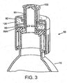
- FIG. 3 is a cutaway view similar to FIG. 2 , but with the shuttle valve 90 pushed downwardly, with the bottom end of the nipple 100 contacting the surface of the storage member 80.
- the ports 92A in the valve member are at least partially aligned with the slot openings 66A formed in the cap member boss 66.
- the supplement material 120 is dispensed through the aligned openings and ports, and into the liquid in the bottle 10.
- the nipple 100 is still in a closed position relative to the valve 90, so that the contents of the bottle cannot be drawn through the valve 90.
- the user may tap the nipple and valve to cause the movement between the closed state shown in FIG. 2 and the dispensing state shown in FIG. 3 .
- the user may shake the bottle and assembled cap system to ensure full dispensing of the supplement material from the storage member into the bottle, and facilitate dissolving or mixing of the supplement with the bottle contents.
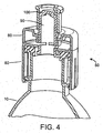
- FIG. 4 is a cutaway view similar to FIG. 3 , but with the nipple 100 pulled up and in an open state relative to the valve 90. In this position, the ports 96 on the tip of the valve are exposed, and provide ports through with the user may drink the bottle contents.
- the valve 90 has remained in the dispensing position relative to the storage member 80.
- the valve may be fitted with a projecting feature that allows the valve to be pushed from the storage position to the dispensing position, but due to engagement with the bottom of the cap member 60 is prevented from being pulled back to the storage position.
- the valve member 90 may be raised to the storage position as the nipple is opened.
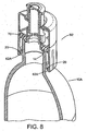
- FIG. 5 is a cutaway view of a bottle 10' with the cap system 50 installed on the bottle neck.
- the bottle 10' has a somewhat large neck diameter than that of the bottle 10, and yet the same cap system is configured to seal and install on the bottle neck.
- This is due to the use of an expandable attach system as provided by the finger portions 62 of the cap member, and the seal 70 with its seal surface broad enough to seal against necks of different sizes.
- the seal surface provided by the seal member 70 is conical, which can increase the seal pressure for larger diameter bottle neck openings, and/or accommodate differences in the distance between the top of the neck and the neck flange for different bottle types.
- a connection which accommodates different neck sizes is employed.
- An exemplary embodiment of a bottle cap dispensing system may accommodate bottle necks of different dimensions, so that one cap dispensing system can be used with several bottle sizes, e.g. with different neck heights (flange to neck opening), and various bottle neck opening diameters. Exemplary ranges are from 5 mm to 25 mm (neck height range) and 18 mm to 30 mm (diameter range of bottle neck openings). A typical diameter range is from 26.5 mm to 28 mm.
- FIG. 6 An alternate dispensing cap system 50' is illustrated in FIG. 6 .
- the cap is similar to the embodiment illustrated in FIGS. 1A-5 .
- the cap member 60' has a plurality of fill openings 65 formed in the web surface 64.
- the fill openings provide a means to allow the product to be dispensed to be filled into the supplement storage member 80' after it has been attached or assembled to the cap member 60'.
- a liquid or powder supplement material can be loaded into the storage member through the fill openings, e.g. by pouring the supplement into the openings with the cap/storage member assembly in an inverted position.
- the bottle seal member 70 is inserted into the cap and pushed against the bottom of the web surface to seal the fill openings.
- the capacity of the storage container 80' is increased in relation to that of storage container 80 ( FIGS. 1-5 ) by increasing the depth dimension in this exemplary embodiment.
- FIG. 6 The embodiment 50' of FIG. 6 is further illustrated in the assembled, cut-away view of FIG. 7 .
- the seal member 70 is shown in the seal position, closing off the fill openings 65 formed in the cap member surface 64.
- FIG. 7 illustrates another feature of the bottle cap assembly 50'. Since some bottles have different neck-flange-to-neck-top-surface dimensions, at least some of the finger portions 62 of the cap member 60' are formed with two sets of barb portions, the barb tip 62A and an intermediate barb portion 62B. In the disclosed embodiment, each of the finger portions is formed with the barb tip portion and the intermediate barb portion. In other embodiments, fewer than all the finger portions may be fabricated with both, one, or none of the barb portions. Moreover, in other embodiments, some of the finger portions may have only a tip barb portion, and others may have only an intermediate barb portion.
- the intermediate barb portions 62B with the tip barb portions 62A enables the bottle cap assembly 50' to accommodate even more variations in the bottle neck.
- the intermediate barb portions 62B may engage the flange to hold the cap assembly in place.
- the barb tip portions may engage the flange to hold the cap assembly in place.
- the versatility of the bottle cap assembly 50' in accommodating bottle necks of different neck opening sizes and flange dimensions is illustrated in the cutaway views of FIGS. 8 , 9 and 10 .
- the bottle 10A has a relatively longer distance between the flange 20 and the neck opening surface 14.
- the bottle cap assembly is secured to the bottle by engagement of the tip barb portions with the flange 20.
- the neck opening of the bottle also has a relatively smaller diameter, with the surface 14 engaging the seal closer to the inward edge of the seal.
- FIG. 9 shows the cap assembly 50' in sealed position on the neck of another bottle 10B, this bottle having a somewhat larger neck opening diameter than that of bottle 10A, so that the neck surface 14 engages the seal surface of the seal member 70 in a position further away from the center of the seal member.
- the distance from the neck opening to the flange 20 is still relatively large, and the tip barb portions 62A are engaging the flange to hold the assembly 50' in sealed position to the bottle neck.
- FIG. 10 shows the cap assembly 50' in sealed position on the neck of yet another bottle 10C, this bottle, having a somewhat smaller neck opening diameter than that of bottle 10C, so that the neck surface 14 engages the seal surface of the seal member 70 in a position closer to the center of the seal member.
- the distance from the neck opening to the flange 20 is relatively smaller than that of bottles 10A and 10B, and the intermediate barb portions 62B are engaging the flange to hold the assembly 50' in sealed position to the bottle neck.
- the cap member is provided with two barb positions relative to the bottle neck opening 14, i.e. the barb position of tip portion 62A and the barb position of intermediate barb portion 62B.
- more than two barb portions positions may be provided, either on each finger portions or at staggered finger portions.
- This may provide a single bottle cap assembly configuration to accommodate more than two or three different bottle sizes.
- the bottle sizes are typically determined by a drink manufacturer, say a bottled water purveyor, sports drink purveyor or other drink vendor.
- Providing flexibility in the dispensing cap assembly to accommodate multiple bottle types provides the advantage of reducing the number of different types of dispensing cap assemblies needed to fit to the multiple bottle types.
- a cap system 150 has the same overall function as the cap system 50 and other cap systems of the prior embodiments.
- a shuttle valve of this embodiment, valve 190 will lock into position when moved (pressed) into its lowermost or low position, thereby remaining fully open to the supplement storage compartment in spite of shaking during mixing of liquid and supplement, and in spite of movement of nipple 200, and other usage and jostling. This promotes and/or ensures a good mix of water and supplement and using all supplement.
- Nipple 200 is the same or similar to nipple 100 and other nipples in the previous embodiments. It is sized to fit over shuttle valve 190.
- a nipple seat and storage compartment member 210 Around nipple 200 is a nipple seat and storage compartment member 210.
- This storage compartment member 210 is preferably of a rigid plastic, such as other rigid plastic members disclosed herein.
- the nipple at its lower end preferably has a rib that mates with a rib of the storage compartment member 210 to limit the upward movement of the nipple, or by other means that are well known in the art for sports bottle type nipples.
- Storage compartment member 210 has a hollow circumferential section 220 open at its lower end for mating with an upper portion of a cap member 160 thereby forming a storage compartment 220A for supplement.
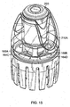
- the storage compartment member 210 has two opposing curved indentations 210A so that even when the nipple 200 is in the downmost position (e.g., as shown in FIG. 15 ), portions of the nipple are exposed to easily grasp the nipple with a finger and opposing thumb to lift the nipple from the closed position to an open position (uppermost position of the nipple, e.g., FIG. 13 ), so that a user may drink from the bottle.
- the storage member 210 has an inner bottom ring portion 210B to mate with an upper surface of ring 166 of web portion 164 of the cap member. There may be small ribs to form a slight interference fit and thus a better seal to keep the supplement in the chamber.
- cap member 160 that functions the same or similar to the cap member 60 and other cap members of the prior embodiments.
- cap member 160 has a lower portion with a plurality of finger portions 162 projecting from a web portion 164.
- the finger portions 162 are the same or substantially the same as in the prior embodiments, and preferably as depicted here with two barbs or tabs that operate the same as in the prior embodiments, forming an attach portion for attaching the cap system and in particular the cap member to the bottle.
- the web portion has a hollow upwardly projecting ring portion 166, i.e. projecting above the web portion away from the finger portions.
- the ring portion 166 has a plurality of spaced dispensing openings 166A formed between adjacent posts 166B, and these openings will allow the supplement material to pass through when the shuttle valve member openings 190A are aligned with the these openings 166A of the storage chamber, as described more fully below with reference to FIG. 13 .
- the cap member 160 further includes an outer circumferential surface 164A and a circumferential vertical wall 164B extending upwardly from the web portion 164 and together defining the outer circumferential surface 164A.
- Surface 164A receives a bottom circumferential edge of the storage compartment member 210.
- the storage compartment member 210 has an inwardly projecting circumferential rib 220B that snap fits over and mates with an outwardly projecting circumferential rib 164C from wall 164B, the rib 164C being of slightly greater diameter than that of rib 220B, thereby providing an attach feature of the storage compartment member 210 to the cap member.
- the cap system also includes a seal member assembly 170 that fits into cap member 160, i.e., sized to fit snugly within a barrel of the cap member formed by the fingers and pressed upwardly against an underside of the web portion 164 of the cap member.
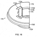
- the seal member assembly comprises two members, a seal member 172 and a rigid member 174.
- the seal member 172 is resilient and preferably fabricated of an elastomeric material, such as, by way of example only, thermoplastic rubber (TPR) (molded rubber), SBR, neoprene rubber, or closed cell foam, and has a center opening configured for concentricity with the opening through the boss.
- TPR thermoplastic rubber
- SBR neoprene rubber
- closed cell foam closed cell foam
- the rigid member 174 is a rigid plastic of a type disclosed herein or other type of rigid member.
- the rigid member 174 has upper tabs 174A that engage slots 172A of the seal member 172 and an upper interior substantially annular surface 174B that receives a corresponding annular downwardly depending tab 172B of the seal member 172.
- the seal member assembly 170 includes a center opening through which the bottle contents may pass, and a generally flat upper surface 74.
- the outer periphery of the seal member 172 includes a downwardly extending peripheral wall 172E that also extends or tapers outwardly, and even more so at its lower and outermost portion 172F to frictionally engage the inner portion of the web member barrel, e.g., as shown in FIG. 11 .
- This shape allows the seal member 172 to slide into the barrel relatively easily, but the outermost portion 172F tends to expand if one attempts to move it downward from the barrel.
- the seal member also has an inwardly tapered lower surface 172D defining a partial conical seal surface which may be contacted by the bottle neck lip when the cap system is attached to the bottle neck, e.g., as shown in the embodiment of FIG. 3 .
- the web portion 164 has an opening or openings 164D through which supplement can be inserted into the chamber.
- the chamber could also be filled in advance, prior to assembly, then snapped on to the cap member at the web portion, in which case the openings 164D would not be needed but could still be present.
- the member 210 may be fabricated of a semi-transparent or transparent plastic material such as, by way of example only, styrene, and is configured for attachment to the cap member by snap fit mentioned above, although adhesive, welding or other connection method could be used. As noted elsewhere herein, single use is preferred for the cap system, although multiple use is possible. Shipment with the chamber filled, or subsequent filling by the user are possible.
- the dispensing cap system 150 further includes the shuttle valve member 190 having a hollow generally cylindrical wall portion 192, and a top web portion 194 at one end thereof which extends across the end of the wall portion and is for mating with the nipple when the nipple is closed to flow of liquid.
- a bottom of the shuttle valve has tabs or fingers 190B that have a gripping projection 190C at their ends. The gripping portions engage a bottom inner annular portion 174C of the rigid member 174 of the seal assembly to hold the shuttle valve 190 securely in the open position as best shown in FIG. 13 .
- boss surfaces or tabs 190D to act as downward motion stoppers that engage the upper portion of annular portion 174C.
- a tip 196 of reduced diameter relative to the wall portion 192 extends above the surface of the web portion 194.
- the sidewall of the tip has several ports (e.g., such as shown as 96A in earlier embodiments) formed therein, and permit the beverage to pass through from the bottle when the valve is in an open position.
- the diameter of the wall portion 192 is sized in cooperation with the diameter of the opening in the storage member, so that the cylindrical wall portion tightly but slidably fits within the opening.
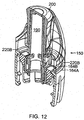
- the shuttle valve has a range of sliding movement within the storage member, and the nipple has a range of sliding movement on the shuttle valve, such that, when the nipple and shuttle valve are in a closed position as in FIG. 11 , the ports are sealed by the nipple. In an open position as in FIG. 12 , the nipple does not cover the ports 196A, allowing liquid to pass through from the bottle, so the user can drink the beverage.
- valve 190 is positioned so that the boss surfaces or tabs 190D may be positioned such that against the upper portion of annular portion 174C and act as temporary downward motion stoppers. However, friction also would act to prevent premature opening of the valve. Further, packaging for the cap system in shipping and otherwise handling would preferably be such to help prevent premature opening of the valve.
- the interior volume of the storage member 210 when filled with a quantity of supplement material, cannot flow out through openings 166A because the openings 190A of the shuttle valve are not aligned. They are blocked by the solid wall portion of the shuttle valve 190.
- the nipple 200 and shuttle valve 190 may be pressed down by the user, resulting in the tabs 190D passing downward below the annular portion 174C and engaging the lower surface of the annular portion.
- There is an annular gap between the openings 190A and openings 166 so that actual alignment of the openings 190A with openings 166 is not necessary for the system to operate, although alignment would be preferred.
- the user shakes the bottle until a good mix is achieved.
- the openings 190A positively stay in communication with the openings 166, thus allowing complete mixing.
- FIG. 13 shows the drinking position of the nipple 200, which has been pulled upward to its topmost position, opening communication with the ports in the shuttle valve.
- the shuttle valve 190 stays down.
- the resiliency is such that the downward force needed to apply the fingers to the bottle neck sufficiently to form a good seal between the seal member and bottle is less than the deformation point and failure point of the bottle. At least ten, or at least twelve or at least fourteen fingers helps to provide good flexibility and resiliency to the fingers to help reduce the downward force of application to the bottle, and yet achieve a strength of attachment to the bottle such that pulling up on the nipple in order to drink will not pull the cap system off of the bottle.
- the force required to apply the cap member to the bottle must be less than such force that would cause the user to apply so much resisting force to the bottle that the user would cause the bottle to be crushed or otherwise fail.
Landscapes
- Engineering & Computer Science (AREA)
- Mechanical Engineering (AREA)
- Closures For Containers (AREA)
- Package Specialized In Special Use (AREA)
Claims (15)
- Système de capuchon de distribution (150) pour distribuer un matériau (120) à travers une ouverture de goulot de bouteille et dans la bouteille pour se mélanger avec le contenu de la bouteille, comprenant :un élément de capuchon (160) ayant une partie d'âme (164) et une structure de raccordement pour la mise en prise sans filetage avec le goulot de la bouteille ;un élément de joint d'étanchéité (172) ayant une surface de joint d'étanchéité agencée pour le contact étanche avec le goulot de la bouteille, la surface de joint d'étanchéité étant suffisante pour fournir le contact étanche avec des goulots de bouteille de différentes tailles d'ouverture ;un élément de stockage (210) assemblé à l'élément de capuchon (160) et ayant un volume de stockage pour contenir le matériau (120) ;un élément de valve (190) ayant un ou plusieurs orifices de valve (196A) et un ou plusieurs orifices de distribution (190A), l'élément de valve (190) étant configuré pour le mouvement coulissant entre une position de stockage dans laquelle le volume de stockage est scellé et une position de distribution dans laquelle un ou plusieurs orifices de distribution (166A) dans l'élément de capuchon (160) sont ouverts pour permettre au matériau (120) de traverser le volume de stockage pour se mélanger avec le contenu de la bouteille ;un mamelon de valve (200) configuré pour s'adapter sur l'élément de valve (190) pour le mouvement coulissant entre une position fermée de valve et une position ouverte dans laquelle le contenu de la bouteille est autorisé à traverser l'élément de valve pour être consommé par un utilisateur ;ladite structure de raccordement comprenant un ensemble de parties de doigt (162) en suspension vers le bas à partir de la partie d'âme (164) et ayant des extrémités distales, les parties de doigt ayant des parties de mise en prise pour mettre en prise une bride de goulot d'une bouteille vers l'intérieur des parties de doigt (162), l'élément de capuchon (160) ayant la résiliente suffisante de sorte que les parties de doigt (162) peuvent s'évaser vers l'extérieur pour permettre aux parties de doigt de passer sur une bride de goulot lorsque l'élément de capuchon (160) est installé sur le goulot et pour permettre aux parties de mise en prise de mettre en prise la bride afin de fixer l'élément de capuchon sur le goulot de bouteille,dans lequel il y a également un élément rigide (174) fixé sur l'élément de joint d'étanchéité (172) pour mettre en prise une partie inférieure de l'élément de valve (190) lorsque l'élément de valve (190) est dans la position de distribution pour maintenir l'élément de valve (190) dans la position de distribution.
- Système selon la revendication 1, dans lequel au moins certaines des parties de mise en prise sur les doigts (162) sont des parties d'ardillon s'étendant radialement vers l'intérieur par rapport aux doigts (162).
- Système selon la revendication 1, dans lequel les parties de mise en prise sont disposées entre les extrémités distales des parties de doigt (162) et la partie d'âme (164).
- Système selon la revendication 1, dans lequel les parties de mise en prise comprennent un premier ensemble de parties de mise en prise positionné au niveau des extrémités distales d'au moins certaines desdites parties de doigt (162) et un second ensemble de parties de mise en prise positionné entre les extrémités distales d'au moins certaines desdites parties de doigt (162) et la partie d'âme (164).
- Système selon la revendication 1, dans lequel l'élément de joint d'étanchéité (172) est fabriqué avec un matériau élastomère, de sorte que la surface de joint d'étanchéité est compressible pour permettre la mise en prise d'étanchéité avec le goulot de la bouteille lorsque les parties de doigt (162) mettent en prise la bride de goulot de bouteille.
- Système selon la revendication 1, dans lequel la surface de joint d'étanchéité a une forme généralement conique.
- Système selon la revendication 1, dans lequel l'élément de joint d'étanchéité (172) s'adapte parfaitement à l'intérieur d'un corps cylindrique de l'élément de capuchon (160).
- Système selon la revendication 1, dans lequel l'élément de stockage (210) est assemblé à l'élément de capuchon (160) et comprend une paroi externe définissant une périphérie externe du volume de stockage pour y maintenir le matériau (120), l'élément de stockage (210) ayant une ouverture formée à travers la paroi externe en alignement avec l'ouverture dans l'élément de capuchon (160).
- Système selon la revendication 1, dans lequel l'élément de valve (190) est un élément de valve généralement cylindrique comprenant un élément de paroi généralement cylindrique (192), avec un élément de bride au niveau d'une première extrémité et une pointe de valve (196) ayant un ou plusieurs orifices de valve (196A) au niveau de la pointe et un ou plusieurs orifices de distribution (190A) disposés de manière adjacente à la première extrémité, l'élément de valve (190) étant configuré pour le mouvement coulissant à l'intérieur de l'ouverture dans l'élément de stockage (210) entre une position de stockage dans laquelle les orifices de distribution (166A) sont bloqués par l'élément de valve (190) et la position de distribution dans laquelle les un ou plusieurs orifices de distribution (166A) sont alignés avec un orifice (190A) correspondant dans l'élément de valve (190) pour permettre au matériau (120) de traverser le volume de stockage ; et dans lequel le mamelon de valve (200) est configuré pour s'adapter sur la valve (190) pour le mouvement coulissant entre une position fermée de valve avec les orifices de valve (196A) fermés par le mamelon de valve (200) et la position ouverte dans laquelle les orifices de valve (196A) sont ouverts.
- Système selon la revendication 1, dans lequel l'élément de joint d'étanchéité (172) a une surface coudée s'étendant vers le bas pour mettre en prise et sceller l'ouverture de goulot de différentes bouteilles ayant des diamètres différents.
- Système selon la revendication 1, dans lequel il y a un premier ensemble de parties de mise en prise sur au moins certaines desdites parties de doigt (162) et positionné à une première distance de la partie d'âme (164) pour mettre en prise la bride de goulot des bouteilles ayant une première distance prédéterminée de leur ouverture de goulot à la bride de goulot, et un second ensemble de parties de mise en prise positionné entre les extrémités distales d'au moins certaines desdites parties de doigt (162) et la partie d'âme (164) et à une seconde distance de la partie d'âme pour mettre en prise la bride de goulot des bouteilles ayant une seconde distance prédéterminée de leur ouverture de goulot à la bride de goulot.
- Système selon la revendication 2 ou 3, dans lequel les parties de mise en prise sont des parties d'ardillon.
- Système selon la revendication 4, dans lequel le premier ensemble de parties de mise en prise et le second ensemble de parties de mise en prise sont des parties d'ardillon.
- Système selon la revendication 1, dans lequel les parties de mise en prise sont disposées au niveau des extrémités distales des parties de doigt (162).
- Système selon la revendication 9, dans lequel les parties de mise en prise s'étendent radialement vers l'intérieur par rapport aux parties de doigt (162) et une partie inférieure des parties de mise en prise se coude vers le haut, lorsqu'elles s'étendent vers l'intérieur afin de faciliter l'évasement vers l'extérieur des parties de doigt (162).
Applications Claiming Priority (3)
| Application Number | Priority Date | Filing Date | Title |
|---|---|---|---|
| US12/789,861 US8083055B2 (en) | 2010-05-28 | 2010-05-28 | Dispensing cap system for beverage bottles |
| US12/983,813 US8141700B2 (en) | 2010-05-28 | 2011-01-03 | Bottle cap for dispersing powdered supplement in situ |
| PCT/US2011/000456 WO2011149501A1 (fr) | 2010-05-28 | 2011-03-11 | Bouchon de bouteille destiné à disperser un supplément poudreux in situ |
Publications (3)
| Publication Number | Publication Date |
|---|---|
| EP2576371A1 EP2576371A1 (fr) | 2013-04-10 |
| EP2576371A4 EP2576371A4 (fr) | 2014-04-02 |
| EP2576371B1 true EP2576371B1 (fr) | 2016-10-19 |
Family
ID=45004238
Family Applications (1)
| Application Number | Title | Priority Date | Filing Date |
|---|---|---|---|
| EP11787003.0A Not-in-force EP2576371B1 (fr) | 2010-05-28 | 2011-03-11 | Bouchon de bouteille destiné à disperser un supplément poudreux in situ |
Country Status (15)
| Country | Link |
|---|---|
| US (1) | US8141700B2 (fr) |
| EP (1) | EP2576371B1 (fr) |
| JP (1) | JP5810154B2 (fr) |
| KR (1) | KR20130090791A (fr) |
| CN (1) | CN102971225B (fr) |
| AU (1) | AU2011258892B2 (fr) |
| BR (1) | BR112012030256A2 (fr) |
| CA (1) | CA2798768A1 (fr) |
| EA (1) | EA024342B1 (fr) |
| IL (1) | IL223218A0 (fr) |
| MX (1) | MX2012013251A (fr) |
| PH (1) | PH12012502262A1 (fr) |
| SG (1) | SG185540A1 (fr) |
| WO (1) | WO2011149501A1 (fr) |
| ZA (1) | ZA201208408B (fr) |
Families Citing this family (54)
| Publication number | Priority date | Publication date | Assignee | Title |
|---|---|---|---|---|
| US9452870B1 (en) | 1987-01-20 | 2016-09-27 | Michael Anderson | Two-piece double-sealed dispensing capsule with button blast and drink through feature |
| US8701906B1 (en) | 2008-12-31 | 2014-04-22 | Blast Max Llc | Ingredient dispensing cap for mixing beverages with push-pull drinking spout |
| USD672237S1 (en) * | 2011-01-11 | 2012-12-11 | Tap the Cap, Inc. | Bottle cap for powdered supplement |
| US9567142B1 (en) | 2011-05-27 | 2017-02-14 | Michael Anderson | One-piece dispensing capsule with integral plunger |
| US20130092699A1 (en) * | 2011-08-18 | 2013-04-18 | Richard Qi Li | Beverage can sealer and holder |
| GB2501138B (en) * | 2012-04-11 | 2014-07-30 | Tamm Inc | Removable bottle cap assembly |
| NL2009188C2 (nl) * | 2012-07-16 | 2014-01-20 | Low Lands Lab B V | Afsluitelement voor het losmaakbaar afsluiten van een houder. |
| US8950608B2 (en) * | 2012-10-14 | 2015-02-10 | Chad A. Dejong | Universal adapter system for bottle containers using a dispensing pump or cap |
| US9051099B2 (en) * | 2012-12-13 | 2015-06-09 | Jose Rodrigo Oliva SALINAS | One piece dispensing lid |
| CN103010593B (zh) * | 2012-12-26 | 2014-06-04 | 广东海兴塑胶有限公司 | 一种带储存溶质的饮料瓶 |
| EP2765089A1 (fr) * | 2013-02-07 | 2014-08-13 | Francesco La Pica | Fermeture pour récipient muni d'un bec verseur |
| US9795242B2 (en) | 2013-02-14 | 2017-10-24 | Cirkul, Inc. | Additive delivery systems and containers |
| US9102441B1 (en) | 2013-09-20 | 2015-08-11 | Bradley Orvik | Compartmentalized dispensing lid for beverage container |
| PL3169600T3 (pl) | 2014-07-18 | 2018-07-31 | Moradi Consulting Gmbh | Wieczko do umieszczania na pojemniku na ciecz |
| GB2521895B (en) * | 2014-09-25 | 2015-12-16 | Grenade Uk Ltd | Drinking vessel |
| US10888826B2 (en) | 2014-11-21 | 2021-01-12 | Cirkul, Inc. | Adjustable additive cartridge systems and methods |
| ES2748334T3 (es) * | 2014-11-21 | 2020-03-16 | Cirkul Inc | Sistemas de cartuchos de aditivos ajustables |
| HK1247064A1 (zh) | 2014-12-05 | 2018-09-21 | 生活燃料有限公司 | 用於优化水合和用於添加剂的背景分配的系统和设备 |
| US10674857B2 (en) | 2014-12-05 | 2020-06-09 | LifeFuels, Inc. | Portable system for dispensing controlled quantities of additives into a beverage |
| WO2016106433A1 (fr) | 2014-12-30 | 2016-07-07 | Moradi Consulting Gmbh | Corps de distribution sous forme de capsules servant à distribuer des additifs à un liquide |
| CN104555056B (zh) * | 2015-01-08 | 2016-08-24 | 珠海经济特区龙狮瓶盖有限公司 | 饮品瓶盖 |
| US10231567B2 (en) | 2015-06-11 | 2019-03-19 | LifeFuels, Inc. | System, method, and apparatus for dispensing variable quantities of additives and controlling characteristics thereof in a beverage |
| US10913647B2 (en) | 2015-06-11 | 2021-02-09 | LifeFuels, Inc. | Portable system for dispensing controlled quantities of additives into a beverage |
| US10889424B1 (en) | 2019-09-14 | 2021-01-12 | LifeFuels, Inc. | Portable beverage container systems and methods for adjusting the composition of a beverage |
| US10655264B2 (en) | 2015-08-04 | 2020-05-19 | Whirlpool Corporation | Laundry treating appliance with internal housing |
| AT517987B1 (de) * | 2015-11-24 | 2019-03-15 | Toifl Werner | Verschluss |
| US10442672B2 (en) * | 2015-11-30 | 2019-10-15 | HAOYU Xing | Water taking device for barreled water bucket |
| US20170340521A1 (en) * | 2016-05-24 | 2017-11-30 | Michael S. Farhi | Clip-on nipple assembly |
| CN110612050B (zh) | 2017-02-22 | 2022-09-09 | 奇库尔公司 | 添加剂输送控制系统和方法 |
| US12017191B2 (en) | 2017-03-06 | 2024-06-25 | Cirkul, Inc. | Adjustable additive delivery systems and dispensing closure valves for the same |
| IT201700033118U1 (it) * | 2017-03-27 | 2018-09-27 | Vigeo S R L | Sistema per la raccolta di campioni bioptici |
| US10293991B2 (en) | 2017-04-15 | 2019-05-21 | Better Tmrw Llc | Two channeled bottle pourer |
| USD856083S1 (en) | 2018-01-05 | 2019-08-13 | LifeFuels, Inc. | Bottle including additive vessels |
| USD887769S1 (en) | 2018-01-05 | 2020-06-23 | LifeFuels, Inc. | Additive vessel |
| US11337533B1 (en) | 2018-06-08 | 2022-05-24 | Infuze, L.L.C. | Portable system for dispensing controlled quantities of additives into a beverage |
| CN108652182B (zh) * | 2018-08-09 | 2024-03-19 | 曼盛包装(上海)有限公司 | 一种带出液结构的梳子 |
| US10512358B1 (en) | 2018-10-10 | 2019-12-24 | LifeFuels, Inc. | Portable systems and methods for adjusting the composition of a beverage |
| CN109515967A (zh) * | 2018-11-19 | 2019-03-26 | 张春倩 | 一种即配式饮料瓶盖 |
| US11148847B2 (en) * | 2019-05-01 | 2021-10-19 | Pepsico, Inc. | Plastic neck outsert for metal beverage container |
| JP7625539B2 (ja) | 2019-05-24 | 2025-02-03 | ユニリーバー・アイピー・ホールディングス・ベスローテン・ヴェンノーツハップ | 濃縮詰め替えカプセル用のカプセルおよびキャップアセンブリ |
| CN113874122A (zh) * | 2019-05-24 | 2021-12-31 | 联合利华知识产权控股有限公司 | 用于浓缩再填充囊的盖组件 |
| WO2020239617A1 (fr) | 2019-05-24 | 2020-12-03 | Unilever N.V. | Système de capuchon pour une capsule de recharge concentrée |
| AR118986A1 (es) | 2019-05-24 | 2021-11-17 | Unilever Nv | Cápsula y tapón para una cápsula de recarga concentrada |
| JP7581246B2 (ja) | 2019-05-24 | 2024-11-12 | ユニリーバー・アイピー・ホールディングス・ベスローテン・ヴェンノーツハップ | 濃縮詰め替えカプセル用のカプセルおよびプラグ |
| US10981772B1 (en) | 2019-09-14 | 2021-04-20 | LifeFuels, Inc. | Portable beverage container systems and methods for adjusting the composition of a beverage |
| FR3105186B1 (fr) * | 2019-12-20 | 2021-11-12 | Abc Transfer | Conteneur etanche comprenant un dispositif permettant un raccordement amovible a une enceinte |
| US12338041B2 (en) | 2019-12-26 | 2025-06-24 | Pharmunion, LLC | Stable lactase product |
| US12128009B1 (en) | 2020-04-25 | 2024-10-29 | Cirkul, Inc. | Systems and methods for bottle apparatuses, container assemblies, and dispensing apparatuses |
| US11903516B1 (en) | 2020-04-25 | 2024-02-20 | Cirkul, Inc. | Systems and methods for bottle apparatuses, container assemblies, and dispensing apparatuses |
| WO2022016012A1 (fr) | 2020-07-15 | 2022-01-20 | Cirkul, Inc. | Distributeurs portatifs de carbonatation |
| CN111703728B (zh) * | 2020-07-26 | 2024-11-15 | 江苏金羚羊食品有限公司 | 一种下压式即配型容器用瓶盖和容器 |
| US12458165B1 (en) | 2020-10-16 | 2025-11-04 | Cirkul, Inc. | Systems and methods for adjusting content of a beverage |
| US20240025603A1 (en) * | 2020-10-30 | 2024-01-25 | C-Loop Packaging Sweden Ab | Patterned can end modular dispensing systems with enhanced recyclability |
| KR102830296B1 (ko) | 2023-05-17 | 2025-07-03 | 배재대학교 산학협력단 | 다기능 쉐이커 |
Family Cites Families (98)
| Publication number | Priority date | Publication date | Assignee | Title |
|---|---|---|---|---|
| US2813649A (en) | 1955-06-30 | 1957-11-19 | Lipari Michael | Receptacles |
| US2807384A (en) | 1956-03-12 | 1957-09-24 | Lipari Michael | Compartmental dispensing receptacle |
| US2793776A (en) | 1956-05-23 | 1957-05-28 | Lipari Michael | Container attachment for providing a compartmental dispensing receptacle |
| US3019932A (en) | 1958-12-12 | 1962-02-06 | Frank K Singiser | Universal cap |
| US3156369A (en) | 1962-09-19 | 1964-11-10 | Ethicon Inc | Bicameral container |
| IT948526B (it) | 1972-02-03 | 1973-06-11 | Inge Spa | Dispositivo di tappatura per botti glie flaconi e simili con capsula a vite e contenitore fratturabile per l iniziale separata conserva zione di componenti del prodotto confezionato |
| JPS5124618Y2 (fr) * | 1973-05-18 | 1976-06-23 | ||
| US3924741A (en) * | 1975-03-04 | 1975-12-09 | Gibson Ass Inc | Two-compartment container |
| US4221291A (en) | 1978-06-20 | 1980-09-09 | General Foods Corporation | Container having separate storage facilities for two materials |
| US4195730A (en) | 1978-06-20 | 1980-04-01 | General Foods Corporation | Container having separate storage facilities for two materials |
| DE8502008U1 (de) | 1985-01-26 | 1985-08-29 | Celamerck Gmbh & Co Kg, 6507 Ingelheim | Verschlußkappe für Zweikomponentenpackungen |
| DE3524289A1 (de) * | 1985-07-06 | 1987-01-08 | Fischer Artur Dr H C | Vorrichtung zum ausspritzen eines bindemittels fuer die verankerung eines befestigungselementes in einem bohrloch |
| US4727985A (en) | 1986-02-24 | 1988-03-01 | The Boc Group, Inc. | Mixing and dispensing apparatus |
| DE3837595A1 (de) * | 1988-04-14 | 1990-05-10 | Goldwell Gmbh | Doppelkammer-behaelter |
| US4865189A (en) * | 1988-08-24 | 1989-09-12 | Alcon Laboratories, Inc. | Device for storage, mixing, and dispensing of two different fluids |
| US4911316A (en) | 1989-04-27 | 1990-03-27 | Cap Snap Co. | Plastic bottle cap sealing plural neck profiles |
| BE1003997A6 (fr) | 1990-03-09 | 1992-09-08 | Continental Photo | Element d'eclairage chimiluminescent tubulaire. |
| US5314084A (en) * | 1992-08-21 | 1994-05-24 | The West Company, Incorporated | Two piece all plastic seal |
| JPH0715559U (ja) * | 1993-05-31 | 1995-03-14 | 浩 津守 | 吐出容器 |
| US5419445A (en) | 1994-06-24 | 1995-05-30 | Kaesemeyer; David M. | Container for storing, mixing and dispensing |
| ES2137013T3 (es) | 1995-07-29 | 1999-12-01 | Rocep Lusol Holdings | Aparato para mezclar un fluido y un liquido. |
| US5678720A (en) | 1995-10-27 | 1997-10-21 | Amhil Enterprises | Lid for disposable containers of differing sizes |
| DE19635833C2 (de) * | 1996-09-04 | 1998-08-06 | Henkel Kgaa | Zwei-Komponenten-Behälter |
| US5960972A (en) * | 1996-11-15 | 1999-10-05 | Constancio Larguia, Sr. | Container cap with interlocked safety closure |
| US6113257A (en) | 1996-12-26 | 2000-09-05 | M.L.I.S. Projects Ltd. | Two-compartment container |
| US5794802A (en) | 1997-03-04 | 1998-08-18 | Caola; Joseph | Container for separation, storage, and mixing of ingredients |
| US6513650B2 (en) | 1997-10-14 | 2003-02-04 | Biogaia Ab | Two-compartment container |
| US6786330B2 (en) | 1997-10-14 | 2004-09-07 | Biogaia Ab | Two-compartment container |
| US5927549A (en) | 1998-03-20 | 1999-07-27 | Aptargroup, Inc. | Dispensing structure with frangible membrane for separating two products |
| JP2000072185A (ja) * | 1998-08-28 | 2000-03-07 | Toto Ltd | 二液混合容器 |
| JP2000103454A (ja) * | 1998-09-29 | 2000-04-11 | Daiwa Can Co Ltd | 飲料充填容器キャップ |
| US6152296A (en) | 1998-11-06 | 2000-11-28 | Shih; Kuang-Sheng | Additive holder for a pet bottle |
| US6372270B1 (en) | 1999-05-26 | 2002-04-16 | Sean P. Denny | Drink mix apparatus for making personal quantities of beverage |
| AU6066799A (en) | 1999-11-26 | 2001-05-31 | Lily Hsu | Container device for separately enclosing two different substances |
| US20010035387A1 (en) | 2000-03-01 | 2001-11-01 | Sutcliffe-Noyd Tami Leigh | Universal baby bottle cap |
| US6945394B2 (en) * | 2000-06-20 | 2005-09-20 | Segovia Jr Eugenio | Beverage device |
| AU2002225842A1 (en) | 2000-11-01 | 2002-05-15 | James A. Vlodek | Closure with selectively operable dispense feature |
| US6959841B2 (en) | 2000-11-01 | 2005-11-01 | Vlodek James A | Closure with selectively operable dispense feature |
| US6527110B2 (en) | 2000-12-01 | 2003-03-04 | Brett Moscovitz | Device for storing and dispensing a substance by mating with a container and associated methods |
| US6533113B2 (en) | 2000-12-01 | 2003-03-18 | Brett Moscovitz | System, devices and methods for storing and mixing substances |
| JP2002211622A (ja) | 2001-01-23 | 2002-07-31 | Mikuni Corp | 内容物混合用キャップ |
| US6540070B1 (en) | 2001-08-20 | 2003-04-01 | Christopher J Conwell | Water bottle attachment with releasable concentrated flavor |
| US6702161B2 (en) | 2001-12-12 | 2004-03-09 | Portola Packaging, Inc. | Closure having rotatable spout and axially movable stem |
| DE10202147A1 (de) | 2002-01-17 | 2003-09-18 | Birkmayer Gesundheitsprodukte | Kunststoff-Flaschenverschluss |
| JP3636143B2 (ja) * | 2002-02-15 | 2005-04-06 | タイガー魔法瓶株式会社 | 液体保温容器 |
| KR20040072287A (ko) | 2003-02-10 | 2004-08-18 | 조영국 | 이종물질을 실시간 혼합시킬 수 있는 용기의 마개 |
| KR20030093938A (ko) | 2002-06-04 | 2003-12-11 | 조영국 | 이종물질을 실시간 혼합시킬 수 있는 용기의 마개 |
| ES2275874T3 (es) | 2002-04-30 | 2007-06-16 | BORMIOLI ROCCO & FIGLIO S.P.A. | Capsula que contiene una sustancia para mezclar en botellas que contienen liquidos presurizados. |
| US6854595B2 (en) | 2002-07-15 | 2005-02-15 | Danny Kiser | Container closure containing a mix |
| JP2004075133A (ja) | 2002-08-20 | 2004-03-11 | Nippon Tansan Gas Co Ltd | 容器の封止機構及びその機構に使用するキャップ |
| US7210575B2 (en) | 2002-09-26 | 2007-05-01 | Boehringer Ingelheim International Gmbh | Two-component packaging unit |
| US6912878B2 (en) * | 2003-02-24 | 2005-07-05 | Alpha Security Products, Inc. | Bottle security device |
| US6974024B2 (en) | 2003-04-12 | 2005-12-13 | Young Kook Cho | Cap device for mixing different kinds of materials separately contained therein and in bottle |
| US6935493B2 (en) | 2003-04-12 | 2005-08-30 | Young Kook Cho | Cap device for mixing different kinds of materials separately contained therein and in bottle |
| US6994211B2 (en) | 2003-04-12 | 2006-02-07 | Young Kook Cho | Cap device for mixing different kinds of materials separately contained therein and in bottle |
| US7172095B2 (en) * | 2003-04-18 | 2007-02-06 | Christopher John Marshall | Bottle closure containing beverage concentrate |
| AU2003204438B1 (en) * | 2003-05-30 | 2004-02-05 | Sailnote Pty Ltd. | Hair colourant applicator |
| US20070023300A1 (en) | 2003-06-18 | 2007-02-01 | Donald Spector | Universal bottle cap having a dissolvable membrane |
| US20050218015A1 (en) | 2003-06-18 | 2005-10-06 | Donald Spector | Universal bottle cap |
| US6962254B2 (en) | 2003-06-18 | 2005-11-08 | Donald Spector | Universal bottle cap |
| US6820740B1 (en) | 2003-06-18 | 2004-11-23 | Donald Spector | Universal cap for dispensing materials by retrofit upon existing bottled beverage containers |
| US6926138B1 (en) | 2003-08-18 | 2005-08-09 | Mark Floyd Basham | Bottle cap including an additive dispenser |
| DE10341112A1 (de) | 2003-09-05 | 2005-03-31 | Li-Li Yehhsu | Behälter mit separaten Speicherkammern |
| ES2340288T3 (es) * | 2003-10-28 | 2010-06-01 | Andrey Vyacheslavovich Agarkov | Depositos para productos de componentes multiples. |
| JP4714696B2 (ja) | 2003-11-22 | 2011-06-29 | リー、ジュン ミン | 第2物質の貯蔵空間を有する瓶の蓋及びそれを用いる製品 |
| US20050184024A1 (en) | 2004-02-19 | 2005-08-25 | Santa Cruz Cathy D. | Bottle-cap having an internal compartment |
| JP4580726B2 (ja) | 2004-10-08 | 2010-11-17 | 日本高圧電気株式会社 | 飲料容器のキャップ構造 |
| JP4453105B2 (ja) | 2004-10-29 | 2010-04-21 | 株式会社吉野工業所 | 二剤混合容器 |
| JP4535261B2 (ja) | 2004-10-29 | 2010-09-01 | 株式会社吉野工業所 | 二剤混合容器 |
| ATE510778T1 (de) * | 2004-11-04 | 2011-06-15 | Viz Entpr Llc | Mehrkammerbehälter und kappe dafür |
| JP2006131283A (ja) | 2004-11-08 | 2006-05-25 | Nicchu Saisei Shigen Kk | 容器の蓋体構造 |
| KR100634354B1 (ko) | 2004-11-23 | 2006-10-16 | 조영국 | 첨가제 첨가용 위조방지 이중캡 |
| US7484633B1 (en) | 2005-03-25 | 2009-02-03 | Moher Laura E | Container system for the storage and mixing of stored ingredients |
| US7055685B1 (en) * | 2005-04-27 | 2006-06-06 | Brent Patterson | Mixing cap and method for use thereof |
| US7909160B2 (en) * | 2005-04-27 | 2011-03-22 | Abrigo, Ltd | Mixing cap and method for use thereof |
| US20080289976A1 (en) | 2005-06-27 | 2008-11-27 | Henry John R | Container attachable to another container for mixing ingredients |
| EP1752381A1 (fr) | 2005-08-12 | 2007-02-14 | Obrist Closures Switzerland GmbH | Bouchon |
| US7588142B1 (en) | 2005-11-18 | 2009-09-15 | Rexam Closures And Containers Inc. | Additive delivery system closure |
| US20070215496A1 (en) | 2006-03-17 | 2007-09-20 | Scarborough Ella B | Bottle assembly |
| US20090321286A1 (en) * | 2006-08-11 | 2009-12-31 | Bernard Frutin | Container closure having a lifting cap for introducing an additive into the contents of the container |
| WO2008026939A1 (fr) * | 2006-08-31 | 2008-03-06 | Alto Packaging Limited | Bouchon de contenant à libération de pression |
| KR20080035708A (ko) | 2006-10-20 | 2008-04-24 | 조영국 | 용기의 마개 |
| US20080116086A1 (en) | 2006-11-22 | 2008-05-22 | Hung Chien-Lung | Bottle cap type additive container |
| US20080202950A1 (en) | 2007-02-27 | 2008-08-28 | Anderson Michael R | Container cap having dispensing storage chamber |
| US8443969B2 (en) | 2007-03-16 | 2013-05-21 | The Coca-Cola Company | Ingredient release spout |
| US8276748B2 (en) | 2007-03-16 | 2012-10-02 | The Coca-Cola Company | Ingredient release spout |
| CN101970128B (zh) * | 2007-06-28 | 2015-05-20 | 米德韦斯特瓦科卡尔玛公司 | 瓶和用于容器的阀配件 |
| DE102007046625B4 (de) * | 2007-09-27 | 2012-06-06 | Gaplast Gmbh | Vorrichtung zum getrennten Aufbewahren einer Substanz, vorzugsweise eines medizinischen oder pharmazeutischen Wirkstoffs, und einer Flüssigkeit und zum Mischen derselben vor dem Gebrauch |
| US20090194533A1 (en) | 2008-02-04 | 2009-08-06 | Lizerbram Eric K | Closure with additive reservoir |
| US8142827B2 (en) | 2008-04-16 | 2012-03-27 | Georgia Crown Distributing Co. | Packaged bottle beverage having an ingredient release closure with improved additive release and method and apparatus thereof |
| US20090308831A1 (en) | 2008-06-13 | 2009-12-17 | Anderson Michael R | Pouch carton and container fitments for use with any ingredients |
| EP2143657A1 (fr) | 2008-07-10 | 2010-01-13 | Nestec S.A. | Fermeture de récipient |
| US20110108509A1 (en) | 2008-07-11 | 2011-05-12 | Raoul Eugenio Fontana | Container closure |
| US8230777B2 (en) * | 2008-07-21 | 2012-07-31 | Nutra-Life, Inc. | Water container cap for holding additives to water |
| WO2010028172A1 (fr) | 2008-09-03 | 2010-03-11 | Flava' Cap Llc | Appareil de fermeture universel avec système de distribution |
| WO2010044515A1 (fr) * | 2008-10-17 | 2010-04-22 | Lee Jeong-Min | Capsule de bouteille |
| GB2471994B (en) | 2009-07-15 | 2011-10-19 | Genmont Biotech Inc | Bottle cap capable of adding additive |
| WO2011098865A1 (fr) | 2010-02-12 | 2011-08-18 | Raoul Eugenio Fontana | Fermeture de contenant |
-
2011
- 2011-01-03 US US12/983,813 patent/US8141700B2/en not_active Expired - Fee Related
- 2011-03-11 WO PCT/US2011/000456 patent/WO2011149501A1/fr not_active Ceased
- 2011-03-11 CA CA2798768A patent/CA2798768A1/fr not_active Abandoned
- 2011-03-11 EA EA201291221A patent/EA024342B1/ru not_active IP Right Cessation
- 2011-03-11 AU AU2011258892A patent/AU2011258892B2/en not_active Ceased
- 2011-03-11 BR BR112012030256A patent/BR112012030256A2/pt not_active IP Right Cessation
- 2011-03-11 JP JP2013512592A patent/JP5810154B2/ja not_active Expired - Fee Related
- 2011-03-11 KR KR1020127033416A patent/KR20130090791A/ko not_active Ceased
- 2011-03-11 MX MX2012013251A patent/MX2012013251A/es active IP Right Grant
- 2011-03-11 PH PH1/2012/502262A patent/PH12012502262A1/en unknown
- 2011-03-11 EP EP11787003.0A patent/EP2576371B1/fr not_active Not-in-force
- 2011-03-11 SG SG2012083390A patent/SG185540A1/en unknown
- 2011-03-11 CN CN201180026201.3A patent/CN102971225B/zh not_active Expired - Fee Related
-
2012
- 2012-11-08 ZA ZA2012/08408A patent/ZA201208408B/en unknown
- 2012-11-22 IL IL223218A patent/IL223218A0/en unknown
Also Published As
| Publication number | Publication date |
|---|---|
| CN102971225A (zh) | 2013-03-13 |
| EA201291221A1 (ru) | 2013-09-30 |
| US20110290678A1 (en) | 2011-12-01 |
| EP2576371A4 (fr) | 2014-04-02 |
| PH12012502262A1 (en) | 2013-02-11 |
| JP5810154B2 (ja) | 2015-11-11 |
| MX2012013251A (es) | 2013-03-12 |
| ZA201208408B (en) | 2014-01-29 |
| CA2798768A1 (fr) | 2011-12-01 |
| WO2011149501A1 (fr) | 2011-12-01 |
| EA024342B1 (ru) | 2016-09-30 |
| CN102971225B (zh) | 2016-08-03 |
| EP2576371A1 (fr) | 2013-04-10 |
| BR112012030256A2 (pt) | 2016-08-09 |
| SG185540A1 (en) | 2012-12-28 |
| IL223218A0 (en) | 2013-02-03 |
| US8141700B2 (en) | 2012-03-27 |
| KR20130090791A (ko) | 2013-08-14 |
| JP2013545673A (ja) | 2013-12-26 |
| AU2011258892A1 (en) | 2012-12-20 |
| AU2011258892B2 (en) | 2016-07-28 |
Similar Documents
| Publication | Publication Date | Title |
|---|---|---|
| AU2011258892B2 (en) | Bottle cap for dispersing powdered supplement in situ | |
| US8083055B2 (en) | Dispensing cap system for beverage bottles | |
| US20120223100A1 (en) | Bottle cap for dispersing powdered supplement in situ | |
| RU2388672C2 (ru) | Контейнер для напитков | |
| EP2670678B1 (fr) | Capuchon distributeur pour contenant | |
| US6874664B1 (en) | Push-pull dispenser with folding fingers | |
| US6202876B1 (en) | Push and twist locking child-resistant and container | |
| US6450352B1 (en) | Child-resistant push and twist locking cap | |
| US20140166510A1 (en) | Container Closure Having Means For Introducing An Additive Into The Contents Of The Container | |
| MXPA02011589A (es) | Aditamento y ensamble de cierre surtidor resellable para sellado a alta presion y surtido bimodal. | |
| RU2254275C2 (ru) | Выливное устройство и укупорочный колпачок со встроенным выливным устройством | |
| GB2523797A (en) | Container assembly | |
| CN1984821A (zh) | 封闭盖 | |
| WO2015184396A1 (fr) | Capuchon de bouteille universel | |
| CN101460368A (zh) | 储藏和饮用容器 | |
| US7490719B2 (en) | Volumetric dispenser | |
| WO2014172588A2 (fr) | Bec verseur pourvu d'un ensemble raccord auto-collant pouvant être monté sur celui-ci | |
| US11440710B2 (en) | Self-venting closure | |
| US12522410B2 (en) | Self-venting closure | |
| EP2203358B9 (fr) | Fermeture non réutilisable pour embouchures filetées | |
| EP4733222A1 (fr) | Bouchon et récipient le comprenant | |
| HK1190686B (en) | Dispensing cap for a container |
Legal Events
| Date | Code | Title | Description |
|---|---|---|---|
| PUAI | Public reference made under article 153(3) epc to a published international application that has entered the european phase |
Free format text: ORIGINAL CODE: 0009012 |
|
| 17P | Request for examination filed |
Effective date: 20121221 |
|
| AK | Designated contracting states |
Kind code of ref document: A1 Designated state(s): AL AT BE BG CH CY CZ DE DK EE ES FI FR GB GR HR HU IE IS IT LI LT LU LV MC MK MT NL NO PL PT RO RS SE SI SK SM TR |
|
| RIN1 | Information on inventor provided before grant (corrected) |
Inventor name: SIMONIAN, JEANNINE, NMI Inventor name: FETTES, IAN, J. Inventor name: SIMONIAN, CHRISTOPHER, H.Y. |
|
| RAP1 | Party data changed (applicant data changed or rights of an application transferred) |
Owner name: TAP THE CAP, INC. |
|
| RIN1 | Information on inventor provided before grant (corrected) |
Inventor name: SIMONIAN, CHRISTOPHER, H.Y. Inventor name: SIMONIAN, JEANNINE, NMI Inventor name: FETTES, IAN, J. |
|
| RIN1 | Information on inventor provided before grant (corrected) |
Inventor name: SIMONIAN, JEANNINE, NMI Inventor name: SIMONIAN, CHRISTOPHER, H.Y. Inventor name: FETTES, IAN, J. |
|
| RAP1 | Party data changed (applicant data changed or rights of an application transferred) |
Owner name: PEP INNOVATIONS, INC. |
|
| DAX | Request for extension of the european patent (deleted) | ||
| A4 | Supplementary search report drawn up and despatched |
Effective date: 20140228 |
|
| RIC1 | Information provided on ipc code assigned before grant |
Ipc: B65D 47/24 20060101ALI20140224BHEP Ipc: B65D 25/08 20060101AFI20140224BHEP Ipc: B65D 53/02 20060101ALI20140224BHEP Ipc: B65D 51/28 20060101ALI20140224BHEP |
|
| 17Q | First examination report despatched |
Effective date: 20150728 |
|
| GRAP | Despatch of communication of intention to grant a patent |
Free format text: ORIGINAL CODE: EPIDOSNIGR1 |
|
| INTG | Intention to grant announced |
Effective date: 20160510 |
|
| GRAS | Grant fee paid |
Free format text: ORIGINAL CODE: EPIDOSNIGR3 |
|
| GRAA | (expected) grant |
Free format text: ORIGINAL CODE: 0009210 |
|
| AK | Designated contracting states |
Kind code of ref document: B1 Designated state(s): AL AT BE BG CH CY CZ DE DK EE ES FI FR GB GR HR HU IE IS IT LI LT LU LV MC MK MT NL NO PL PT RO RS SE SI SK SM TR |
|
| REG | Reference to a national code |
Ref country code: GB Ref legal event code: FG4D |
|
| REG | Reference to a national code |
Ref country code: CH Ref legal event code: EP |
|
| REG | Reference to a national code |
Ref country code: AT Ref legal event code: REF Ref document number: 838107 Country of ref document: AT Kind code of ref document: T Effective date: 20161115 |
|
| REG | Reference to a national code |
Ref country code: IE Ref legal event code: FG4D |
|
| REG | Reference to a national code |
Ref country code: DE Ref legal event code: R096 Ref document number: 602011031507 Country of ref document: DE |
|
| REG | Reference to a national code |
Ref country code: CH Ref legal event code: NV Representative=s name: E. BLUM AND CO. AG PATENT- UND MARKENANWAELTE , CH |
|
| REG | Reference to a national code |
Ref country code: NL Ref legal event code: MP Effective date: 20161019 |
|
| REG | Reference to a national code |
Ref country code: LT Ref legal event code: MG4D |
|
| PG25 | Lapsed in a contracting state [announced via postgrant information from national office to epo] |
Ref country code: LV Free format text: LAPSE BECAUSE OF FAILURE TO SUBMIT A TRANSLATION OF THE DESCRIPTION OR TO PAY THE FEE WITHIN THE PRESCRIBED TIME-LIMIT Effective date: 20161019 |
|
| REG | Reference to a national code |
Ref country code: AT Ref legal event code: MK05 Ref document number: 838107 Country of ref document: AT Kind code of ref document: T Effective date: 20161019 |
|
| PG25 | Lapsed in a contracting state [announced via postgrant information from national office to epo] |
Ref country code: LT Free format text: LAPSE BECAUSE OF FAILURE TO SUBMIT A TRANSLATION OF THE DESCRIPTION OR TO PAY THE FEE WITHIN THE PRESCRIBED TIME-LIMIT Effective date: 20161019 Ref country code: GR Free format text: LAPSE BECAUSE OF FAILURE TO SUBMIT A TRANSLATION OF THE DESCRIPTION OR TO PAY THE FEE WITHIN THE PRESCRIBED TIME-LIMIT Effective date: 20170120 Ref country code: SE Free format text: LAPSE BECAUSE OF FAILURE TO SUBMIT A TRANSLATION OF THE DESCRIPTION OR TO PAY THE FEE WITHIN THE PRESCRIBED TIME-LIMIT Effective date: 20161019 Ref country code: NO Free format text: LAPSE BECAUSE OF FAILURE TO SUBMIT A TRANSLATION OF THE DESCRIPTION OR TO PAY THE FEE WITHIN THE PRESCRIBED TIME-LIMIT Effective date: 20170119 |
|
| PG25 | Lapsed in a contracting state [announced via postgrant information from national office to epo] |
Ref country code: FI Free format text: LAPSE BECAUSE OF FAILURE TO SUBMIT A TRANSLATION OF THE DESCRIPTION OR TO PAY THE FEE WITHIN THE PRESCRIBED TIME-LIMIT Effective date: 20161019 Ref country code: AT Free format text: LAPSE BECAUSE OF FAILURE TO SUBMIT A TRANSLATION OF THE DESCRIPTION OR TO PAY THE FEE WITHIN THE PRESCRIBED TIME-LIMIT Effective date: 20161019 Ref country code: PL Free format text: LAPSE BECAUSE OF FAILURE TO SUBMIT A TRANSLATION OF THE DESCRIPTION OR TO PAY THE FEE WITHIN THE PRESCRIBED TIME-LIMIT Effective date: 20161019 Ref country code: PT Free format text: LAPSE BECAUSE OF FAILURE TO SUBMIT A TRANSLATION OF THE DESCRIPTION OR TO PAY THE FEE WITHIN THE PRESCRIBED TIME-LIMIT Effective date: 20170220 Ref country code: NL Free format text: LAPSE BECAUSE OF FAILURE TO SUBMIT A TRANSLATION OF THE DESCRIPTION OR TO PAY THE FEE WITHIN THE PRESCRIBED TIME-LIMIT Effective date: 20161019 Ref country code: RS Free format text: LAPSE BECAUSE OF FAILURE TO SUBMIT A TRANSLATION OF THE DESCRIPTION OR TO PAY THE FEE WITHIN THE PRESCRIBED TIME-LIMIT Effective date: 20161019 Ref country code: BE Free format text: LAPSE BECAUSE OF FAILURE TO SUBMIT A TRANSLATION OF THE DESCRIPTION OR TO PAY THE FEE WITHIN THE PRESCRIBED TIME-LIMIT Effective date: 20161019 Ref country code: IS Free format text: LAPSE BECAUSE OF FAILURE TO SUBMIT A TRANSLATION OF THE DESCRIPTION OR TO PAY THE FEE WITHIN THE PRESCRIBED TIME-LIMIT Effective date: 20170219 Ref country code: HR Free format text: LAPSE BECAUSE OF FAILURE TO SUBMIT A TRANSLATION OF THE DESCRIPTION OR TO PAY THE FEE WITHIN THE PRESCRIBED TIME-LIMIT Effective date: 20161019 |
|
| REG | Reference to a national code |
Ref country code: DE Ref legal event code: R097 Ref document number: 602011031507 Country of ref document: DE |
|
| PG25 | Lapsed in a contracting state [announced via postgrant information from national office to epo] |
Ref country code: SK Free format text: LAPSE BECAUSE OF FAILURE TO SUBMIT A TRANSLATION OF THE DESCRIPTION OR TO PAY THE FEE WITHIN THE PRESCRIBED TIME-LIMIT Effective date: 20161019 Ref country code: CZ Free format text: LAPSE BECAUSE OF FAILURE TO SUBMIT A TRANSLATION OF THE DESCRIPTION OR TO PAY THE FEE WITHIN THE PRESCRIBED TIME-LIMIT Effective date: 20161019 Ref country code: RO Free format text: LAPSE BECAUSE OF FAILURE TO SUBMIT A TRANSLATION OF THE DESCRIPTION OR TO PAY THE FEE WITHIN THE PRESCRIBED TIME-LIMIT Effective date: 20161019 Ref country code: DK Free format text: LAPSE BECAUSE OF FAILURE TO SUBMIT A TRANSLATION OF THE DESCRIPTION OR TO PAY THE FEE WITHIN THE PRESCRIBED TIME-LIMIT Effective date: 20161019 Ref country code: EE Free format text: LAPSE BECAUSE OF FAILURE TO SUBMIT A TRANSLATION OF THE DESCRIPTION OR TO PAY THE FEE WITHIN THE PRESCRIBED TIME-LIMIT Effective date: 20161019 |
|
| PLBE | No opposition filed within time limit |
Free format text: ORIGINAL CODE: 0009261 |
|
| STAA | Information on the status of an ep patent application or granted ep patent |
Free format text: STATUS: NO OPPOSITION FILED WITHIN TIME LIMIT |
|
| PG25 | Lapsed in a contracting state [announced via postgrant information from national office to epo] |
Ref country code: IT Free format text: LAPSE BECAUSE OF FAILURE TO SUBMIT A TRANSLATION OF THE DESCRIPTION OR TO PAY THE FEE WITHIN THE PRESCRIBED TIME-LIMIT Effective date: 20161019 Ref country code: SM Free format text: LAPSE BECAUSE OF FAILURE TO SUBMIT A TRANSLATION OF THE DESCRIPTION OR TO PAY THE FEE WITHIN THE PRESCRIBED TIME-LIMIT Effective date: 20161019 Ref country code: BG Free format text: LAPSE BECAUSE OF FAILURE TO SUBMIT A TRANSLATION OF THE DESCRIPTION OR TO PAY THE FEE WITHIN THE PRESCRIBED TIME-LIMIT Effective date: 20170119 |
|
| 26N | No opposition filed |
Effective date: 20170720 |
|
| REG | Reference to a national code |
Ref country code: DE Ref legal event code: R119 Ref document number: 602011031507 Country of ref document: DE |
|
| REG | Reference to a national code |
Ref country code: CH Ref legal event code: PL |
|
| GBPC | Gb: european patent ceased through non-payment of renewal fee |
Effective date: 20170311 |
|
| PG25 | Lapsed in a contracting state [announced via postgrant information from national office to epo] |
Ref country code: MC Free format text: LAPSE BECAUSE OF FAILURE TO SUBMIT A TRANSLATION OF THE DESCRIPTION OR TO PAY THE FEE WITHIN THE PRESCRIBED TIME-LIMIT Effective date: 20161019 Ref country code: SI Free format text: LAPSE BECAUSE OF FAILURE TO SUBMIT A TRANSLATION OF THE DESCRIPTION OR TO PAY THE FEE WITHIN THE PRESCRIBED TIME-LIMIT Effective date: 20161019 |
|
| REG | Reference to a national code |
Ref country code: IE Ref legal event code: MM4A |
|
| REG | Reference to a national code |
Ref country code: FR Ref legal event code: ST Effective date: 20171130 |
|
| PG25 | Lapsed in a contracting state [announced via postgrant information from national office to epo] |
Ref country code: DE Free format text: LAPSE BECAUSE OF NON-PAYMENT OF DUE FEES Effective date: 20171003 Ref country code: FR Free format text: LAPSE BECAUSE OF NON-PAYMENT OF DUE FEES Effective date: 20170331 Ref country code: LU Free format text: LAPSE BECAUSE OF NON-PAYMENT OF DUE FEES Effective date: 20170311 |
|
| PG25 | Lapsed in a contracting state [announced via postgrant information from national office to epo] |
Ref country code: GB Free format text: LAPSE BECAUSE OF NON-PAYMENT OF DUE FEES Effective date: 20170311 Ref country code: IE Free format text: LAPSE BECAUSE OF NON-PAYMENT OF DUE FEES Effective date: 20170311 Ref country code: LI Free format text: LAPSE BECAUSE OF NON-PAYMENT OF DUE FEES Effective date: 20170331 Ref country code: CH Free format text: LAPSE BECAUSE OF NON-PAYMENT OF DUE FEES Effective date: 20170331 |
|
| PG25 | Lapsed in a contracting state [announced via postgrant information from national office to epo] |
Ref country code: MT Free format text: LAPSE BECAUSE OF NON-PAYMENT OF DUE FEES Effective date: 20170311 |
|
| PG25 | Lapsed in a contracting state [announced via postgrant information from national office to epo] |
Ref country code: HU Free format text: LAPSE BECAUSE OF FAILURE TO SUBMIT A TRANSLATION OF THE DESCRIPTION OR TO PAY THE FEE WITHIN THE PRESCRIBED TIME-LIMIT; INVALID AB INITIO Effective date: 20110311 |
|
| PG25 | Lapsed in a contracting state [announced via postgrant information from national office to epo] |
Ref country code: ES Free format text: LAPSE BECAUSE OF NON-PAYMENT OF DUE FEES Effective date: 20161019 |
|
| PG25 | Lapsed in a contracting state [announced via postgrant information from national office to epo] |
Ref country code: CY Free format text: LAPSE BECAUSE OF NON-PAYMENT OF DUE FEES Effective date: 20161019 |
|
| PG25 | Lapsed in a contracting state [announced via postgrant information from national office to epo] |
Ref country code: MK Free format text: LAPSE BECAUSE OF FAILURE TO SUBMIT A TRANSLATION OF THE DESCRIPTION OR TO PAY THE FEE WITHIN THE PRESCRIBED TIME-LIMIT Effective date: 20161019 |
|
| PG25 | Lapsed in a contracting state [announced via postgrant information from national office to epo] |
Ref country code: TR Free format text: LAPSE BECAUSE OF FAILURE TO SUBMIT A TRANSLATION OF THE DESCRIPTION OR TO PAY THE FEE WITHIN THE PRESCRIBED TIME-LIMIT Effective date: 20161019 |
|
| PG25 | Lapsed in a contracting state [announced via postgrant information from national office to epo] |
Ref country code: AL Free format text: LAPSE BECAUSE OF FAILURE TO SUBMIT A TRANSLATION OF THE DESCRIPTION OR TO PAY THE FEE WITHIN THE PRESCRIBED TIME-LIMIT Effective date: 20161019 |