EP2576410B1 - Greifanordnung und greifelemente für eine mehrschalengreiferanordnung - Google Patents
Greifanordnung und greifelemente für eine mehrschalengreiferanordnung Download PDFInfo
- Publication number
- EP2576410B1 EP2576410B1 EP11792851.5A EP11792851A EP2576410B1 EP 2576410 B1 EP2576410 B1 EP 2576410B1 EP 11792851 A EP11792851 A EP 11792851A EP 2576410 B1 EP2576410 B1 EP 2576410B1
- Authority
- EP
- European Patent Office
- Prior art keywords
- gripping
- main beam
- beam structure
- pipe
- grab
- Prior art date
- Legal status (The legal status is an assumption and is not a legal conclusion. Google has not performed a legal analysis and makes no representation as to the accuracy of the status listed.)
- Active
Links
Images




Classifications
-
- E—FIXED CONSTRUCTIONS
- E21—EARTH OR ROCK DRILLING; MINING
- E21B—EARTH OR ROCK DRILLING; OBTAINING OIL, GAS, WATER, SOLUBLE OR MELTABLE MATERIALS OR A SLURRY OF MINERALS FROM WELLS
- E21B19/00—Handling rods, casings, tubes or the like outside the borehole, e.g. in the derrick; Apparatus for feeding the rods or cables
- E21B19/14—Racks, ramps, troughs or bins, for holding the lengths of rod singly or connected; Handling between storage place and borehole
- E21B19/15—Racking of rods in horizontal position; Handling between horizontal and vertical position
- E21B19/155—Handling between horizontal and vertical position
-
- B—PERFORMING OPERATIONS; TRANSPORTING
- B66—HOISTING; LIFTING; HAULING
- B66C—CRANES; LOAD-ENGAGING ELEMENTS OR DEVICES FOR CRANES, CAPSTANS, WINCHES, OR TACKLES
- B66C1/00—Load-engaging elements or devices attached to lifting or lowering gear of cranes or adapted for connection therewith for transmitting lifting forces to articles or groups of articles
- B66C1/10—Load-engaging elements or devices attached to lifting or lowering gear of cranes or adapted for connection therewith for transmitting lifting forces to articles or groups of articles by mechanical means
- B66C1/42—Gripping members engaging only the external or internal surfaces of the articles
- B66C1/58—Gripping members engaging only the external or internal surfaces of the articles and deforming the articles, e.g. by using gripping members such as tongs or grapples
- B66C1/59—Tongs for sacks
-
- B—PERFORMING OPERATIONS; TRANSPORTING
- B66—HOISTING; LIFTING; HAULING
- B66C—CRANES; LOAD-ENGAGING ELEMENTS OR DEVICES FOR CRANES, CAPSTANS, WINCHES, OR TACKLES
- B66C3/00—Load-engaging elements or devices attached to lifting or lowering gear of cranes or adapted for connection therewith and intended primarily for transmitting lifting forces to loose materials; Grabs
-
- B—PERFORMING OPERATIONS; TRANSPORTING
- B66—HOISTING; LIFTING; HAULING
- B66C—CRANES; LOAD-ENGAGING ELEMENTS OR DEVICES FOR CRANES, CAPSTANS, WINCHES, OR TACKLES
- B66C3/00—Load-engaging elements or devices attached to lifting or lowering gear of cranes or adapted for connection therewith and intended primarily for transmitting lifting forces to loose materials; Grabs
- B66C3/04—Tine grabs
-
- E—FIXED CONSTRUCTIONS
- E21—EARTH OR ROCK DRILLING; MINING
- E21B—EARTH OR ROCK DRILLING; OBTAINING OIL, GAS, WATER, SOLUBLE OR MELTABLE MATERIALS OR A SLURRY OF MINERALS FROM WELLS
- E21B19/00—Handling rods, casings, tubes or the like outside the borehole, e.g. in the derrick; Apparatus for feeding the rods or cables
- E21B19/14—Racks, ramps, troughs or bins, for holding the lengths of rod singly or connected; Handling between storage place and borehole
Definitions
- This disclosure relates to a gripping assembly with gripping members, as part of a grapple attachment, for grasping and manipulating elongated objects, for example cylindrical elongated objects such as pipes, tubes, trees, etc. or non-cylindrical objects such as I-beams, rectangular or square tubing, etc.
- the grapple attachment is attachable to, for example, a trackhoe, backhoe, excavator or other piece of heavy construction equipment.
- each pipe is individually lifted from or loaded onto the bed of a truck, rail car or pipe rack.
- nylon straps and cables with or without manual calipers, are secured around the pipe than attached to the bucket of an excavator.
- the calipers or nylon straps are placed, as close as possible, at the longitudinal center of the pipe. This is important since being off-center, even by a few centimeters (inches), results in decreased control and unwanted tilt of the pipe.
- Pipe hooks are also used to manipulate the pipe.
- the pipe hooks are located at each end of the pipe and are attached to cables.
- a worker is provided at each end of the pipe to place the hooks and control the motion of the pipe. When unloading the pipe from the truck in this manner, it is dangerous for the worker as the worker can easily fall off of the truck or be hit by or crushed by the pipe.
- Pipeline vacuum lifts are also used to lift large diameter pipes. While a vacuum lift eliminates the need for workers at each pipe end, the vacuum lift needs to be generally centered on the pipe to avoid tilting of the pipe. If the vacuum lift is not centered properly on the pipe, an off center lift occurs creating a tipping movement. This tipping movement can break the vacuum seal between the vacuum lift and the pipe or result in dangerous tilting and loss of control of the pipe. In addition, loss of suction or vacuum power can result in release of the pipe from the vacuum lift resulting in dangerous conditions. In addition, in order to obtain an effective seal of the vacuum lift, the surface of the pipe must be clean without the presence of any dirt, snow or ice.
- Document DE-A-102007034506 discloses a gripper for handling heavy loads having two opposite gripper arms, at which a clamping bracket for actuated accommodation of a load is arranged.
- Document DE-U-29502091 discloses a device for handling pipes of a pipe string, which is composed of a plurality of such pipes, wherein the individual tubes each consist of an inner and an outer tube.
- the subject-matter of the present invention is a grapple attachment used to grasp and manipulate elongated objects as defined in independent claim 1.
- Claims 2-4 define preferred embodiments.
- a gripping assembly with gripping members, as part of a grapple attachment, used to grasp and manipulate elongated objects, for example pipe, is described.
- the described grapple attachment can be used in the pipeline construction industry to grasp and manipulate pipe of varying diameters, including large diameter pipe, for example 50,8 cm (20 inch pipe), but can be used in other industries as well, such as the logging industry, to grasp other objects. It is to be understood that the concepts as described herein can be equally applied to the grasping and manipulating of any elongated objects, whether cylindrical or non-cylindrical, for example pipes, cylindrical tubes, trees, I-beams, square tubes, triangular tubes, etc.
- the grapple attachment allows for the picking of pipe from, and placement of pipe on, a stack of pipes without disturbing or damaging adjacent pipes while providing control over the positioning of the pipe.
- the grapple attachment can also be used to lay pipe, for example in a trench, and to remove pipe.
- the grapple attachment is able to be used on all pipe surface types, including pipe surfaces that are dirty, or snow or ice covered.
- the gripping members are configured to prevent damage, not only to the pipe being manipulated, but to adjacent pipes and the coatings of the adjacent pipes.
- the gripping members are configured so that the gripping pressure will not crush the pipe.
- the grapple attachment uses actuators, for example, to actuate the gripping motion by moving grab arms, for tilting the main beam structure and to alter the positions of the gripping members.
- the actuators described herein can be hydraulic actuators, pneumatic actuators, mechanical actuators such as screw-type actuators or geared actuators, or other actuators suitable for the purpose.
- an open or non-gripping position is one in which first and second grab arms are moved away from each other so that a pipe can fit in the space between the grab arms.
- a closed or gripping position is one in which the grab arms are moved towards each other so that a pipe located between the grab arms is squeezed between the grab arms to permit the pipe to be picked up.
- the configuration of the grab arms results in the pipe being clamped or grasped by the grab arms and not rolled into the grab arms as is typical.
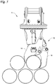
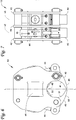
- Figs. 1A and 1B illustrate examples of a grapple attachment 1 provided with a gripping assembly 11 having different embodiments of gripping members 9, 13. Another embodiment of a gripping member 12 is illustrated in Fig. 2 .
- the gripping members 9, 12, 13 are designed to be interchangeably mountable on the gripping assembly 11 to allow alteration of the type of gripping member 9, 12, 13 used on the grapple attachment 1.
- the grapple attachment 1 comprises a bracket attachment 3, a swing drive 106, a lower head assembly 5, tilt actuators 118, 120 and the gripping assembly 11.
- the bracket attachment 3 is configured to attach to a piece of construction equipment, for example an excavator, trackhoe, backhoe, etc. In the illustrated embodiment, the bracket attachment 3 attaches to the construction equipment via a pair of spaced attachment pins 100, 102.
- the swing drive 106 rotates the lower head assembly 5 about a swivel axis a-a (shown in Fig. 10 ) that extends along the x-axis or vertical axis through a centre point of the lower head assembly 5.
- the rotation control includes a hydraulic swing motor 106 that causes rotation of the lower head assembly 5 about the axis a-a driven by the motor 106.
- a hydraulic swivel 108 transfers hydraulic pressure between the stationary/rotating boundary between the bracket attachment 3 and the lower head assembly 5 for use by various hydraulic components of the grapple attachment 1.
- a swing bearing 110 between the bracket attachment 3 and the lower head assembly 5 permits rotation relative to the bracket attachment 3.
- a hydraulic manifold 112 is located in the housing 104 for directing hydraulic fluid to various hydraulic actuators.
- a main hydraulic control valve 114 is mounted on the bracket attachment 3.
- the gripping assembly 11 is pivotally connected to the lower head assembly 5 by a pivot pin 116 so that the gripping assembly 11 can pivot about a pivot axis b-b disposed on a z-axis or lateral axis that is substantially perpendicular to the swivel axis a-a.
- the gripping assembly 11 comprises a longitudinal support structure or main beam structure 14 that supports various embodiments of the gripping members 9, 12, 13.
- the main beam structure 14 extends along a longitudinal axis (y-axis) that is substantially perpendicular to the swivel axis a-a and the pivot axis b-b.
- the main beam structure 14 can have any configuration suitable for supporting the gripping members 9, 12, 13 and performing the other functions of the main beam structure 14 implied by this description.
- the main beam structure 14 is a generally rectangular, tubular beam that has a generally square cross-section.
- the main beam structure 14 can alternatively be, for example, cylindrical or triangular, or be shaped like an I- or H-beam, and can also be a solid structure.
- Tilt actuators 118, 120 are provided for positively controlling pivoting movement of the main beam structure 14 about the pivot axis b-b, thereby controlling the angle of tilt of the gripping assembly 11 and a pipe held thereby.
- the tilt actuators 118, 120 are identical in construction although they could be different if desired.
- the tilt actuators 118, 120 are hydraulic actuators, although other types of actuators could be used, for example pneumatic actuators or mechanical actuators.
- the tilt actuators 118, 120 have a first end connected to the housing 104 of the lower head assembly 5 and a second end connected to the main beam structure 14.
- At least one of the gripping members 13 (as well as the gripping members 9, 12), or both of the gripping members 13, are designed to be adjustable in position relative to the swivel axis a-a and the pivot axis b-b in a direction parallel to the longitudinal axis y.
- the gripping members 9, 12, 13 are slidably disposed on the main beam structure 14.
- the means for slidably disposing the gripping members 9, 12, 13 on the main beam structure 14 and for adjusting the positions of the gripping members 9, 12, 13 on the main beam structure 14 are the same and will be described in the following paragraph with respect to the gripping members 13.
- the gripping members 13 are longitudinally adjustable on the main beam structure 14 by sliding back and forth on the main beam structure 14 in the directions shown by the arrows a1, a2.
- the gripping members 13 are disposed at opposite ends of the main beam structure 14.
- a shift actuator 8 is mounted within the main beam structure 14 along the longitudinal direction thereof.
- the gripping members 13 are connected to one end of the shift actuator 8 via, for example, a fastening pin 7.
- the other end of the longitudinal actuator 8 is fixed to the main beam structure 14 via a fastening means 6, for example, a bolt.
- the shift actuators 8 are illustrated as hydraulic actuators although other types of actuators can be used, such as pneumatic or mechanical actuators.
- Actuation of the shift actuator 8 moves the attached gripping member 13 via the fastening pin 7 along the main beam structure 14 on the longitudinal axis. Actuation of the shift actuator 8 results in the shortening or lengthening of the shift actuator 8. As the fastening pin 7 is connected to one end of the shift actuator 8, the fastening pin 7 thus moves in relation to the shift actuator 8. And, as the gripping member 13 is connected to the fastening pin 7, the gripping member 13 thus moves in relation to the fastening pin 7 and the shift actuator 8. The fastening pin 7 is held within and travels in a longitudinal slot 15 in the main beam structure 14 thereby controlling the pathway of the fastening pin 7. Stops 4 are provided on the main beam structure 14 to limit the range of movement of the gripping members 13 and prevent the gripping members 13 from over travel.
- the gripping members 13 and the shift actuators 8 can be configured to move the gripping members 13 in a number of ways.
- the gripping members 13 can move simultaneously in the same direction such that the distance between the gripping members 13 remains the same.
- the gripping members 13 can be made to move independently of each other, or move simultaneously with each other, to allow adjustment in the distance between the gripping members 13.
- the gripping members 13 are mounted so as to be replaceable by differently configured gripping members 9, 12, 13 designed to perform the broad function of gripping an object, but in different ways or for different sized objects.
- Each of the gripping members 9, 12, 13 includes a support member 130 that includes a main beam structure opening 132 (as shown in Fig. 4 ) extending laterally therethrough that is configured to allow passage of the main beam structure 14 when the gripping member 9, 12, 13 is mounted on the main beam structure 14.
- the support member 130 can take on a number of different configurations as long as the support member 130 can support one or more grab arms as discussed further below, and the support member 130 can be suitably mounted on the main beam structure 14.
- the support members 14 are made from spaced apart metal plates. However, the support members 14 could be forged or molded from solid metal.
- the gripping members 9, 12, 13 are mounted on the main beam structure 14 so that they are movable and can be longitudinally adjusted.
- the gripping member 12 includes a first grab arm 16 and a second grab arm 18 pivotably connected to the first grab arm 16.
- the first grab arm 16 can be pivotably connected to the second grab arm 18.
- the grab arms 16, 18 are positioned so that each grab arm 16, 18 has the same vertical axis v1, i.e. the grab arms 16, 18 are not offset.
- the grab arms 16, 18 could be on different vertical axes, thereby being offset from each other.
- the gripping member 12 includes a first plate 20 and second plate 22 spaced from and parallel to each other.
- the first plate 20 and second plate 22 are connected to each other.
- the plates 20, 22 can be connected by the use of suitable fastening means 23a, 23b, as shown in Figs. 2 and 3 , sufficient to keep the plates 20, 22 spaced and form a strong support member 130.
- the fastening means can be rods, bolts, pins, and/or spacer plates or any other method of fastening.
- a main beam structure opening 21 is provided in each of the plates 20, 22 to receive the main beam structure 14 of the gripping assembly 11.
- the main beam structure openings 21 are aligned with each other to form the opening 132.
- the main beam structure openings 21 are shown as being square in shape, but it is understood that the main beam structure openings 21 can be any shape so long as the main beam structure 14 can be received and the gripping member 12 can not move rotationally on the main beam structure 14.
- the shown main beam structure openings 21 are closed in that they are bounded on all sides by the plate 20, 22.
- the first grab arm 16 is integrally formed with the gripping member 12 and is non-pivotable.
- the second grab arm 18 is pivotably connected between the first plate 20 and the second plate 22.
- a rod as a fastening means 24 is disposed in a tube arm pivot 25 of the second grab arm 18 and the fastening means 24 is connected to the first plate 20 and the second plate 22.
- Other methods of attaching the second grab arm 18 to the plates 20, 22 can be used so long as the second grab arm 18 pivots.
- the second grab arm 18 has a pivot main beam structure 28 and is pivotably connected to one end of an actuator 30.
- the other end of the actuator 30 is pivotably connected between the first plate 20 and second plate 22 of the gripping member 12. Actuation of the actuator 30 moves the second grab arm 18 between an open or non-gripping position and a closed or gripping position.
- the gripping member 12 is mountable on the main beam structure 14 by inserting the main beam structure 14 through the aligned openings 21. Once mounted on the main beam structure 14, the gripping member 12 cannot rotate relative to the main beam structure 14.
- the fastening pin 7 is then connected to the gripping member 12, and the fastening means 6 connected to the actuator 8 and the main beam structure 14, as illustrated in Figures 1A , 1B and 10 . This prevents the gripping member 12 from sliding off of the main beam structure 14.
- the support member 130 and the first and second grab arms 16, 18 define an object receiving area when the first and second grab arms 16, 18 are at the gripping position in which is received an object such as a pipe.
- the object receiving area is disposed below the main beam structure opening 132.
- the object receiving area includes a center C, and the object receiving area and the main beam structure opening 132 are positioned relative to each other such that in a front view of the gripping member as in Fig. 4 , a vertical line L-L extending through the center of the object receiving area also extends through a center of the main beam structure opening 132.
- the gripping members 9, 13 define similar object gripping areas and the relation between the gripping areas and the main beam structure openings is the same.
- a horizontal plane H is located at the tip 17 of the first grab arm 16 and is perpendicular to the vertical line L-L that bisects the main beam structure opening 132.
- the first grab arm 16 has a concave contact surface 26 that has a radius r1 that is, preferably, approximately equal to the radius of the pipe.
- the radius r1 can be, for example, approximately 25,4 cm (10 inches) for use with pipe having a 50,8 cm (twenty inch) outer diameter.
- the concave contact surface 26 may have a radius r1 that is slightly larger than half the diameter of the pipe.
- the second grab arm 18 is preferably configured so that it has a concave contact surface 27 that has a radius r2 that is approximately equal to the radius of the pipe.
- the concave contact surface 27 may have a radius r2 that is slightly larger than half the diameter of the pipe.
- the tip 19 of the second grab arm 18 is configured to be disposed at an angle ⁇ of approximately 40° from the horizontal plane H and at an approximate distance r2 from the centre point C. It is to be understood that the angle ⁇ can be more or less than 40°.
- the first grab arm 16 and second grab arm 18 are configured so that the concave contact surfaces 26, 27 come in contact with the pipe when gripping the pipe.
- each grab arm 16, 18 has a profile that tapers towards a free end.
- the gripping member 12 is configured so that only the second grab arm 18 is movable when the gripping motion is actuated.
- the gripping member 12 is configured so that the first grab arm 16 is movable relative to the second grab arm 18 when the gripping motion is actuated.
- the actuator 30 is used to actuate and move the second grab arm 18 between a gripping and non-gripping position. Load hold valves are incorporated on the actuators 30 such that the second grab arm 18 stays locked in place in the event of a hydraulic hose or pressure failure.
- the grab arms 16, 18 can include resilient pads 31, 32, 33, 34, 35, 36 as shown in Fig. 2 .
- the pads 32, 34 are preferably vulcanized rubber with a steel backing but can be any material, including rubber or plastic, that provides a positive grip while protecting the pipe.
- the pads 32, 34 can be somewhat resilient to aid the pipe to resist lateral and rotational movement once clamped.
- the pads 33, 35 are protection pads that are preferably a UMHW plastic or Nylatron ® , but can be any type of plastic, rubber or other material.
- the pads 33, 35 allow the grab arms 16, 18 to contact adjacent pipes while protecting the contacted pipes from damage and allow the grab arms 16, 18 to slide easily along the contacted pipe.
- the pads 31, 36 are tip pads that can be made of the same material as the pads 32, 34 or the protection pads 33, 35.
- the pads 31, 32, 33, 34, 35, 36 are configured to allow for the removal and replacement of the pads 31, 32, 33, 34, 35, 36.
- the pads 31, 32, 33, 34, 35, 36 are preferably installed on the grab arms 16, 18 so any part of the gripping member 12 that comes in contact with the pipe, or with adjacent pipes, is covered by the pads 31, 32, 33, 34, 35, 36.
- the pads 31, 32, 33, 34, 35, 36 can be provided as one continuous piece or can be provided in sections.
- the grab arm 16, 18 tips 17, 19 extend slightly wider than the diameter of the pipe such that the gripping member 12 can be placed over the pipe.
- the gripping member 12 is configured to limit the amount the second grab arm 18 can move towards the first grab arm 16 when a gripping position is actuated, thus preventing damage to the pipe by crushing. This limitation can be incorporated physically or through electronic controls or software.
- the grab arms 16, 18 do not open to such an extent to permit the gripping member 12 from spanning the top of more than one pipe to prevent picking up more than one pipe.
- the profile of the grab arms 16, 18 guide the grab arms 16, 18 down the curved outer surfaces between two pipes and the narrow free end of the first grab arm 16 permits the first grab arm 16 to more easily fit between adjacent pipes.
- the second grab arm 18 is actuated to a gripping position so that the pipe is securely held within the gripping member 12 and the pipe can be safely lifted.
- the tip 17 of the first grab arm 16 contacts the pipe at approximately the center line of the pipe. The gripping member 12 is thus able to grasp and load or offload the pipes, without disturbing adjacent pipes.
- the gripping member 13 is provided with two grab arms 40 that are movable.
- the gripping member 13 includes a first plate 42 and a second plate 43 spaced apart and parallel to each other.
- the grab arms 40 are pivotably connected to the first and second plates 42, 43.
- Separate actuators 44 are connected to each grab arm 40. One end of each actuator 44 is connected to the respective grab arm 40 and the other end of the actuator 44 is connected to the plates 42, 43.
- the gripping member 13 is configured to be slidably connected to the main beam structure 14 in a manner similar to the gripping member 12. As shown in Fig. 6 , the gripping member 13 is provided with main beam structure openings 46 in the plates 42, 43 where the openings 46 are aligned with each other. When viewing the gripping member 13 from the side, as in Fig. 7 , the grab arms 40 are positioned so that the grab arms 40 have different vertical axes v2, v3, i.e. the grab arms 40 are offset. When offset, the grab arms 40 can be configured so that the grab arms 40 bypass each other when in the gripping position. In another embodiment, the grab arms 40 have the same vertical axis and are not offset.
- the main beam structure openings 46 are shown as being square in shape, but it is understood that the main beam structure openings 46 can be any shape so long as the main beam structure 14 can be received and the gripping member 13 can be mounted on the main beam structure 14.
- the shown main beam structure openings 46 are closed in that they are surrounded on all sides by the plate 42, 43.
- the gripping member 13 includes a third plate 49 that is disposed between and connected to the first plate 42 and the second plate 43.
- the third plate 49 includes a main beam structure opening that aligns with the main beam structure openings 46 of the first plate 42 and the second plate 43.
- One of the grab arms 40 is connected between the first plate 42 and the third plate 49 and the other grab arm 40 is connected between the second plate 43 and the third plate 49 so that the grab arms 40 are on different vertical axes v2, v3.
- a third plate 49 is not necessary as long as a means is provided that allows separation of the grab arms 40. For example, spacers or washers can be inserted between the grab arms 40.
- the plates 42, 43, 49 have a concave contact surface 48 that has a radius approximately equal to half the diameter of the pipe to be moved.
- the concave contact surfaces 48 can have a radius that is slightly larger than the diameter of the pipe to be moved.
- the contact surfaces 48 are not related to the diameter of the pipe and can have any radius or can be a straight edge.
- the grab arms 40 are configured so that they open and close simultaneously. When open, the grab arms 40 preferably extend slightly more than the diameter of a pipe. Preferably, the grab arms 40 do not open to a width that would span the top of more than one pipe to prevent gripping more than one pipe. As the gripping member 13 is lowered, the profile of the grab arms 40 guide the grab arms 40 down and around the curved outer surfaces of the pipe and the narrow free end of the grab arms 40 permits the grab arms 40 to more easily fit between adjacent pipes. Once the grab arms 40 are past the center line of the pipe, the grab arms 40 are actuated so that the pipe is moved up to and against the concave contact surface 48 so that the pipe is securely held within the gripping member 13 and can be safely moved.
- the grab arms 40 are configured so that the front side 41 comes in contact with the pipe when closed around the pipe.
- Each grab arm 40 has a profile that tapers towards a free end.
- the gripping member 13 is configured so that both grab arms 40 move simultaneously when the gripping motion is actuated.
- the actuators 44 are used to actuate and move the grab arms 40.
- Each grab arm 40 has its own actuator 44. Load hold valves are incorporated on the actuators such that the grab arms 40 stay locked in place in the event of a hydraulic hose or pressure failure.
- the free end of the grab arm also has a back side 45.
- the front side 41 of each grab arm 40 is a curved gripping surface whose radius is approximately half the diameter of the pipe.
- the grab arm 40 free end is elongated allowing for pipe to be picked from the center of a pipe rack.
- the concave contact surface 48, the front side 41 and back side 45 of the grab arms 40 can include pads 50, 51, 52.
- the concave contact surface 48 pads 50 are installed to create a generally V-shape allowing for a tight grip.
- the pads 50, 51, 52 can be provided as one continuous pad that covers the entire surface of the grab arms 40 or can be provided as non-continuous individual pieces that cover a major portion of the grab arms 40.
- the pads 50, 51 are preferably vulcanized rubber with a steel backing but can be any material that provides a positive grip while protecting the pipe, including rubbers, plastics or other materials.
- the pads 50, 51 can be somewhat resilient to aid the pipe to resist lateral and rotational movement once clamped.
- Protection pads 52 are preferably a UMHW plastic or Nylatron ® , but can be any type of plastic, rubber or other material. The protection pads 52 allow the grab arms 40 to contact adjacent pipes while protecting the pipes from damage and allows the grab arms 40 to slide easily along the adjacent pipe.
- Grab arm 40 tip pads can be provided and made of the same material as the pads 50, 51 or the protection pads 52.
- the pads 50, 51, 52 are configured to allow for the removal and replacement of the pads 50, 51, 52.
- the pads 50, 51, 52 are preferably installed on the grab arms 40 so any part of the gripping member 13 that comes in contact with the pipe, or with adjacent pipes, is covered by the pads 50, 51, 52.
- the pads 50, 51, 52 can be provided as one continuous piece or can be provided in sections.
- the support member 130 and the grab arms 40 define an object receiving area when the first and second grab arms 40 are at the gripping position in which is received an object such as a pipe.
- the object receiving area is disposed below the main beam structure opening defined by the aligned openings 46.
- the object receiving area includes a center, and the object receiving area and the main beam structure opening are positioned relative to each other such that in a front view of the gripping member as in Figure 6 , a vertical line L-L extending through the center of the object receiving area also extends through a center of the main beam structure opening.
- the gripping member 9 includes two movable grab arms 60.
- Each grab arm 60 contains an elongated section 62 and a shorter section 63, that are integrally connected, where an angle ⁇ is created where the sections 62, 63 meet. Due to the configuration of the grab arms 60, this embodiment creates six points of contact on the pipe. The elongation and angle ⁇ of the grab arms 60 allows for pipe to be picked from a pipe stack without unduly moving the adjacent pipes.
- the gripping member 9 includes a first plate 64 and a second plate 65 spaced apart and parallel to each other.
- the grab arms 60 are pivotably connected to the first and second plates 64, 65.
- Separate actuators 68 are connected to each grab arm 60. One end of the actuator 68 is connected to the grab arm 60 and the other end of the actuator 68 is connected to the plates 64, 65.
- the gripping member 9 is configured to be slidably connected to the main beam structure 14 similar to the gripping members 12, 13. As shown in Fig. 8 , the gripping member 9 is provided with aligned main beam structure openings 70 in the plates 64, 65. In the embodiment shown, the main beam structure openings 70 are shown as being square in shape, but it is understood that the main beam structure openings 70 can be any shape.
- the grab arms 60 are positioned so that the grab arms 60 have different vertical axes v4, v5, i.e. the grab arms 60 are offset.
- the grab arms 60 can be configured so that when offset they bypass each other in the gripping position. In another embodiment, the grab arms 60 have the same vertical axis and are not offset.
- a third plate 66 is disposed between and connected to the first plate 64 and the second plate 65.
- the third plate 66 also includes a main beam structure opening that aligns with the main beam structure openings 70 of the first plate 64 and the second plate 65.
- One of the grab arms 60 is connected between the first plate 64 and the third plate 66 and the other grab arm 60 is connected between the second plate 65 and the third plate 66 so that the grab arms 60 are on different vertical axes v4, v5. It is to be understood that the inclusion of a third plate 66 is not necessary as long as a means is provided that allows separation of the grab arms 60. For example, spacers or washers can be inserted between the grab arms 60.
- the plates 64, 65, 66 have a concave contact surface 67 that has a radius approximately equal to half the diameter of the pipe to be moved.
- the concave contact surface 67 can have a radius that is slightly larger than the diameter of the pipe to be moved.
- the contact surface 67 is not related to the diameter of the pipe and can have any radius or can be a straight edge.
- the grab arms 60 are configured so that they open and close simultaneously. When open, the grab arms 60 preferably extend slightly more than the diameter of a pipe and preferably do not extend wide enough to grip more than one pipe. As the gripping member 9 is lowered, the profile of the grab arms 60 guide the grab arms 60 down and around the curved outer surfaces of the pipe and the narrow free end of the grab arms 60 permits the grab arms 60 to more easily fit between adjacent pipes. Once the grab arms 60 are past the center line of the pipe, the grab arms 60 are actuated so that the pipe is moved up to and against the concave contact surface 67 so that the pipe is securely held within the gripping member 9 and can be safely moved.
- the grab arms 60 are configured so that the contact surfaces 55 come in contact with the pipe when closed around the pipe. In the embodiment shown, there are six points of contact. Each grab arm 60 has a profile that tapers towards a free end. Load hold valves are incorporated on the actuators 68 such that the grab arms 60 stay locked in place in the event of a hydraulic hose or pressure failure.
- the free end of the grab arm 60 has a front side 72 and a back side 73.
- the grab arm 60 free end is elongated allowing for pipe to be picked from the center of a pipe pile.
- the concave contact surface 67, the front side 72 and back side 73 of the grab arms 60 can include pads 74, 75.
- the pads 74 on the concave contact surface 67 are installed in a generally V-shape allowing for a tight grip.
- the pads 74, 75 can be provided as one continuous pad or can be provided as non-continuous individual pieces.
- the pads 74 are preferably vulcanized rubber with a steel backing but can be any material that provides a positive grip while protecting the pipe, including rubbers, plastics or other materials.
- the pads 74 can be somewhat resilient to aid the pipe to resist lateral and rotational movement once clamped.
- Protection pads 75 are preferably a UMHW plastic or Nylatron ® , but can be any type of plastic, rubber or other material. The protection pads 75 allow the grab arms 60 to contact adjacent pipes while protecting the pipes from damage and allows the grab arms 60 to slide easily along the pipe.
- Grab arm 60 tip pads can be provided and made of the same material as the pads 74 or the protection pads 75.
- the pads 74, 75 are configured to allow for the removal and replacement of the pads 74, 75.
- the pads 74, 75 are preferably installed on the grab arms 60 so any part of the gripping member 9 that comes in contact with the pipe, or with adjacent pipes, is covered by the pads 74, 75.
- the pads 74, 75 can be provided as one continuous piece or can be provided in sections.
- the shape or configuration of the grab arms is not limited to the embodiments as described above and can be any shape or configuration that allows for the encompassing and gripping of pipe.
Landscapes
- Engineering & Computer Science (AREA)
- Life Sciences & Earth Sciences (AREA)
- Geology (AREA)
- Mining & Mineral Resources (AREA)
- Mechanical Engineering (AREA)
- Physics & Mathematics (AREA)
- Environmental & Geological Engineering (AREA)
- Fluid Mechanics (AREA)
- General Life Sciences & Earth Sciences (AREA)
- Geochemistry & Mineralogy (AREA)
- Load-Engaging Elements For Cranes (AREA)
- Clamps And Clips (AREA)
Claims (4)
- Greiferbefestigung (1), dadurch gekennzeichnet, dass sie umfasst:eine Bügelbefestigung (3), die dazu ausgestaltet ist, an einem Bauausrüstungsteil befestigt zu werden;eine untere Kopfanordnung (5), die mit der Bügelbefestigung verbunden ist und dazu ausgestaltet ist, um eine Schwenkachse (a-a) rotierbar zu sein;eine Greifanordnung (11), die mit der unteren Kopfanordnung zur Drehbewegung um eine Drehachse (b-b), die zur Schwenkachse im Wesentlichen senkrecht ist, drehbar verbunden ist;die Greifanordnung umfasst eine Hauptbalkenstruktur (14), die sich entlang einer Längsachse erstreckt, die zur Schwenkachse und zur Drehachse im Wesentlichen senkrecht ist, und ein Paar Greifelemente (9, 12, 13), jedes umfassend:ein Stützelement (130), wobei das Stützelement (130) eine einzelne Hauptbalkenstrukturöffnung (21, 46, 70, 132) umfasst, die sich seitlich dadurch erstreckt, die dazu ausgestaltet ist, die Hauptbalkenstruktur (14) der Greifanordnung (11) aufzunehmen, wobei die einzelne Hauptbalkenstrukturöffnung (21, 46, 70, 132) eine verschlossene Öffnung ist, wo, in einer Frontansicht des Stützelementes (130), die verschlossene Öffnung allseits vom Stützelement (130) begrenzt ist;einen ersten Greifarm (16, 40, 60) und einen zweiten Greifarm (18, 40, 60), die mit dem Stützelement (130) verbunden sind, wobei jeder vom ersten Greifarm (16) und vom zweiten Greifarm (18) sich zu einem freien Ende hin verjüngen, zumindest einer von den ersten und zweiten Greifarmen (16, 18) mit dem Stützelement (130) beweglich verbunden ist, die ersten und zweiten Greifarme (16, 18) eine Greifstellung und eine Nicht-Greifstellung haben;einen ersten Aktuator (30, 44, 68), der ein Ende, das mit dem Stützelement (130) verbunden ist, und ein zweites Ende hat, das mit dem einen beweglich verbundenen Greifarm verbunden ist;worin das Stützelement (130) und die ersten und zweiten Greifarme (16, 18) einen Gegenstandsaufnahmebereich definieren, wenn die ersten und zweiten Greifarme (16, 18) in der Greifstellung sind, wobei der Gegenstandsaufnahmebereich unter der Hauptbalkenstrukturöffnung (21, 46, 70, 132) angeordnet ist; unddas Greifelement (9, 12, 13) mit einem Schaltaktuator (8) verbindbar ist, der das das Greifelement (9, 12, 13) entlang der Hauptbalkenstruktur (14) entlang der Längsrichtung derselben betätigen kann, und die einzelne Hauptbalkenstrukturöffnung (21, 46, 70, 132) dem Greifelement (9, 12, 13) ermöglicht, entlang der Hauptbalkenstruktur (14) zu gleiten, worin jedes Greifelement (9, 12, 13) auf der Hauptbalkenstruktur (14) an entgegengesetzten Seiten der Drehachse montiert ist, mit der Hauptbalkenstruktur (14), die sich durch die Hauptbalkenstrukturöffnungen (21, 46, 70, 132) der Greifelemente (9, 12, 13) erstreckt, jedes von der Vielzahl von Greifelementen (9, 12, 13) zwischen der Nicht-Greifstellung und der Greifstellung betätigbar ist, und zumindest eines von den Greifelementen (9, 12, 13) in seiner Stellung auf der Hauptbalkenstruktur (14) relativ zur Schwenkachse und zur Drehachse in einer zur Längsachse parallelen Richtung einstellbar ist, und ein Schaltaktuator (8) innerhalb der Hauptbalkenstruktur (14) angeordnet ist und mit dem einstellbaren Greifelement (9, 12, 13) verbunden ist, um die Stellung des Greifelementes (9, 12, 13) auf der Hauptbalkenstruktur (14) einzustellen.
- Greiferbefestigung nach Anspruch 1, worin jedes der Greifelemente (9, 12, 13) in seiner Stellung auf der Hauptbalkenstruktur einstellbar ist, und ein Paar Schaltaktuatoren (8) innerhalb der Hauptbalkenstruktur angeordnet sind und mit den einstellbaren Greifelementen verbunden sind, um die Stellung der Greifelemente auf der Hauptbalkenstruktur einzustellen.
- Greiferbefestigung nach Anspruch 1, ferner umfassend Kippaktuatoren (118, 120), wobei jeder Kippaktuator ein erstes Ende, das mit der unteren Kopfanordnung verbunden ist, und ein zweites Ende hat, das mit der Hauptbalkenstruktur verbunden ist.
- Greiferbefestigung nach Anspruch 1, worin der Schaltaktuator sich entlang der Längsachse der Hauptbalkenstruktur erstreckt.
Applications Claiming Priority (2)
| Application Number | Priority Date | Filing Date | Title |
|---|---|---|---|
| US12/794,877 US8567836B2 (en) | 2007-08-31 | 2010-06-07 | Gripping assembly and gripping members for a grapple attachment |
| PCT/US2011/037121 WO2011156099A2 (en) | 2010-06-07 | 2011-05-19 | Gripping assembly and gripping members for a grapple attachment |
Publications (3)
| Publication Number | Publication Date |
|---|---|
| EP2576410A2 EP2576410A2 (de) | 2013-04-10 |
| EP2576410A4 EP2576410A4 (de) | 2014-02-12 |
| EP2576410B1 true EP2576410B1 (de) | 2022-01-12 |
Family
ID=45098583
Family Applications (1)
| Application Number | Title | Priority Date | Filing Date |
|---|---|---|---|
| EP11792851.5A Active EP2576410B1 (de) | 2010-06-07 | 2011-05-19 | Greifanordnung und greifelemente für eine mehrschalengreiferanordnung |
Country Status (7)
| Country | Link |
|---|---|
| US (2) | US8567836B2 (de) |
| EP (1) | EP2576410B1 (de) |
| CN (1) | CN102917970B (de) |
| AU (1) | AU2011264570B2 (de) |
| BR (1) | BR112012031270B1 (de) |
| CA (1) | CA2799776C (de) |
| WO (1) | WO2011156099A2 (de) |
Families Citing this family (54)
| Publication number | Priority date | Publication date | Assignee | Title |
|---|---|---|---|---|
| US8567836B2 (en) | 2007-08-31 | 2013-10-29 | Lavalley Industries, Llc | Gripping assembly and gripping members for a grapple attachment |
| CN101970792B (zh) | 2007-08-31 | 2014-03-12 | 勒瓦利工业公司 | 用于钻杆的抓钩装置 |
| KR101210589B1 (ko) * | 2010-01-19 | 2012-12-11 | 인석신 | 천공기용 로드 장착장치 |
| USD645062S1 (en) | 2010-11-30 | 2011-09-13 | Lavalley Industries, Llc | Gripping arm |
| US8328071B2 (en) | 2011-02-17 | 2012-12-11 | Lavalley Industries, Llc | Position adjustable grapple attachment |
| CA2836479C (en) * | 2011-05-26 | 2016-05-24 | Lavalley Industries, Llc | An attachment for making up or breaking out pipe |
| US8926257B2 (en) * | 2012-01-05 | 2015-01-06 | Cnh Industrial America Llc | Gripping device for articulated work machine |
| US9243461B1 (en) * | 2012-01-17 | 2016-01-26 | Loadmaster Universal Rigs, Inc. | Catwalk mechanism and method for installing tubulars on a drill string |
| AU2013295616B2 (en) * | 2012-07-27 | 2017-09-28 | Lavalley Industries, Llc | Grab arm housing for grapple attachment |
| US10093000B2 (en) * | 2012-08-06 | 2018-10-09 | Mcelroy Manufacturing, Inc. | Socket fusion jig |
| US9353500B1 (en) | 2012-10-26 | 2016-05-31 | Cold Stone Shorelines And Retaining Walls, Inc. | Excavator thumb having hardened removable teeth defining a platform beyond a wear and tear surface of thumb |
| SE536961C2 (sv) * | 2012-12-21 | 2014-11-11 | Atlas Copco Rocktech Ab | Gripdon till en borrsträngskomponenthanterare, förfarande för manövrering av gripdon, borrsträngskomponenthanterare samtbergborrigg |
| CN103132933B (zh) * | 2013-02-25 | 2015-04-15 | 吉林大学 | 一种铁钻工夹持拧卸装置 |
| EP2781660B1 (de) * | 2013-03-21 | 2018-04-18 | Caterpillar Global Mining LLC | Hydraulischer aktuator |
| NO20130805A1 (no) | 2013-06-10 | 2014-12-11 | Mhwirth As | Løftearmsammenstilling og fremgangsmåte for å bytte ut en holder i nevnte løftearmsammenstilling |
| US9242410B2 (en) * | 2013-09-17 | 2016-01-26 | Mcelroy Manufacturing, Inc. | Top-loading straddle-mounted pipe fusion machine |
| US9976280B2 (en) | 2014-01-16 | 2018-05-22 | Michael A. Honermann | Skid loader attachment including a rotatable and extendable claw |
| US9551193B2 (en) * | 2014-03-25 | 2017-01-24 | Schramm, Inc. | Drill pipe handling apparatus having improved pipe gripping mechanism |
| US8973244B2 (en) | 2014-04-17 | 2015-03-10 | Lavalley Industries, Llc | Pipe processing tool with pipe deformation members |
| WO2016073982A1 (en) * | 2014-11-07 | 2016-05-12 | Terra Sonic International, LLC | Apparatus and method for a pipe handling system |
| CA2967343C (en) | 2014-11-13 | 2023-02-28 | Lavalley Industries, Llc | An attachment for making up or breaking out pipe |
| US10144619B2 (en) | 2014-11-13 | 2018-12-04 | Lavalley Industries, Llc. | Attachment with vacuum and grab arms |
| US9439363B1 (en) * | 2015-04-27 | 2016-09-13 | Caterpillar Forest Products Inc. | Bracket system for grapple assembly |
| CN104909269B (zh) * | 2015-06-20 | 2017-05-31 | 海安宝虹机械科技有限公司 | 一种起重机起吊装置 |
| GB2544794B (en) * | 2015-11-27 | 2018-08-01 | Eastern Attachments Ltd | Loading vehicle attachments |
| DE102015122891B4 (de) * | 2015-12-29 | 2018-12-06 | Horst Busch Elektro-Technik GmbH | Einspannvorrichtung für ein längliches Bauteil zum Transport, zur Montage und Demontage des Bauteils mittels eines Baufahrzeuges |
| US10844674B2 (en) | 2016-04-29 | 2020-11-24 | Schlumberger Technology Corporation | High trip rate drilling rig |
| WO2017190118A2 (en) * | 2016-04-29 | 2017-11-02 | Schlumberger Technology Corporation | Tubular delivery arm for a drilling rig |
| US10400525B2 (en) | 2016-05-13 | 2019-09-03 | Dr Fabrication Inc. | Rod positioning device |
| CN105904432A (zh) * | 2016-05-24 | 2016-08-31 | 陈薇 | 一种水利工程管件码垛工业机器人 |
| CN105945913A (zh) * | 2016-05-24 | 2016-09-21 | 陈薇 | 一种水利工程施工现场作业自动化设备用抓取机 |
| CN105856251A (zh) * | 2016-05-24 | 2016-08-17 | 陈薇 | 一种水利工程管件码垛工业机器人用夹持机械手 |
| WO2018016472A1 (ja) * | 2016-07-19 | 2018-01-25 | 有限会社ウエスト興業八頭 | 作業車のアーム先端に装着されるアタッチメント、アタッチメントを備えた作業車及びアタッチメント用ブレーキ |
| US20180119501A1 (en) * | 2016-10-28 | 2018-05-03 | VAUGHN KENNEMER, Trustee of the Vaughn Kennemer Trust, u/t/a January 5, 2017 | Catwalk Pipe Restraint System |
| RU2652761C1 (ru) * | 2016-11-30 | 2018-04-28 | Публичное акционерное общество "Невское проектно-конструкторское бюро" | Траверса с захватами за бугели |
| RU2653911C1 (ru) * | 2017-02-28 | 2018-05-15 | Акционерное общество "Инжиниринговая компания "АЭМ-технологии" (АО "АЭМ-технологии") | Траверса модульная |
| US10150652B2 (en) * | 2017-03-27 | 2018-12-11 | Tei Rock Drills, Inc. | Rod and casing handler |
| US10597954B2 (en) | 2017-10-10 | 2020-03-24 | Schlumberger Technology Corporation | Sequencing for pipe handling |
| CN108545467A (zh) * | 2018-05-08 | 2018-09-18 | 上海市第中学 | 一种抓取工具 |
| CZ2018406A3 (cs) * | 2018-08-08 | 2019-10-09 | Robotsystem, S.R.O. | Robotický efektor s lineárními aktuátory a regulací uchopovací síly |
| CZ309817B6 (cs) * | 2019-03-21 | 2023-11-08 | Robotsystem, S.R.O. | Monoblok duálního efektoru ukládání vyhořelého jaderného paliva s regulací uchopovací síly |
| CN111285191B (zh) * | 2020-03-12 | 2023-09-26 | 青岛铱薪工业自动化有限公司 | 一种纱管夹具及割纱设备 |
| US20240021329A1 (en) * | 2020-11-16 | 2024-01-18 | William F. Bianco | Apparatus and methods for grappling instruments |
| CN112460880B (zh) * | 2020-11-18 | 2022-02-18 | 山东省科学院海洋仪器仪表研究所 | 一种防止冰块间粘结附着的方法 |
| CN112554812A (zh) * | 2020-12-09 | 2021-03-26 | 湖南迈通智能装备有限公司 | 一种可自动调平的辅助换杆系统及其控制方法 |
| CN112983021B (zh) * | 2021-02-01 | 2022-04-26 | 广州中穗建设有限公司 | 一种新型装配式建筑用的墙体定位装置 |
| AU2023221940A1 (en) * | 2022-02-21 | 2024-08-08 | Tei Rock Drills, Inc. | Rod and casing handler |
| USD1043763S1 (en) | 2022-10-31 | 2024-09-24 | Nye Manufacturing Ltd. | Stump harvester |
| USD1061628S1 (en) * | 2022-11-01 | 2025-02-11 | Nye Manufacturing Ltd. | Pulverizing attachment |
| USD1051953S1 (en) * | 2022-11-01 | 2024-11-19 | Nye Manufacturing Ltd. | Concrete pulverizer |
| USD1040869S1 (en) * | 2022-11-01 | 2024-09-03 | Nye Manufacturing Ltd. | Concrete pulverizer |
| CN119306102B (zh) * | 2024-11-05 | 2025-04-15 | 灌云连庆工程器材有限公司 | 一种港口集装箱内钢管吊装装置 |
| US12442259B1 (en) | 2024-12-09 | 2025-10-14 | Caterpillar Global Mining Equipment Llc | Positioning system for blast hole drilling operations |
| CN120004114B (zh) * | 2025-04-21 | 2025-06-24 | 洛阳理工学院 | 一种排水管道吊装安装装置 |
Citations (1)
| Publication number | Priority date | Publication date | Assignee | Title |
|---|---|---|---|---|
| US20070013199A1 (en) * | 2005-07-12 | 2007-01-18 | Novatek International, Inc. | Clamping assembly |
Family Cites Families (54)
| Publication number | Priority date | Publication date | Assignee | Title |
|---|---|---|---|---|
| US3231303A (en) * | 1963-04-01 | 1966-01-25 | Robert G Letourneau | Rotatable grapple |
| US3311350A (en) * | 1965-05-18 | 1967-03-28 | Maurice M Irwin | Hydraulic lift attachment for vehicles |
| US3333717A (en) * | 1965-12-15 | 1967-08-01 | Charles A Scaperotto | Attachment for load-handling machinery |
| US3727653A (en) * | 1968-12-06 | 1973-04-17 | Drott Mfg Corp | Tree cutting apparatus |
| US3561615A (en) * | 1969-07-16 | 1971-02-09 | Terry A Forsberg | Pipe positioning and handling device |
| US3719296A (en) * | 1970-09-25 | 1973-03-06 | E Larson | Load handling container apparatus |
| US3713554A (en) * | 1971-02-22 | 1973-01-30 | Peterson Ind Inc | Container dumping apparatus |
| US3817567A (en) * | 1972-06-08 | 1974-06-18 | Lull Eng Co Inc | Versatile utility carriage for mobile loaders |
| US3927778A (en) * | 1973-04-16 | 1975-12-23 | Iowa Mold Tooling Co | Tire changing apparatus |
| US3911981A (en) * | 1974-10-29 | 1975-10-14 | Case Co J I | Tree harvesting apparatus |
| US4212577A (en) * | 1977-06-25 | 1980-07-15 | Swanson Ronald V | Grapple |
| US4486136A (en) * | 1982-09-14 | 1984-12-04 | Howard Edwin L | Device for determining weight of objects being moved |
| US4697509A (en) * | 1986-04-07 | 1987-10-06 | Labounty Roy E | Auto body crushing device |
| US4810019A (en) * | 1987-02-05 | 1989-03-07 | Bruecher Eberhard | Mechanically operated collet chuck for gripping round objects |
| US4858979A (en) * | 1988-07-19 | 1989-08-22 | The United States Of America As Represented By The Administrator, National Aeronautics And Space Administration | Gripping device |
| US4951990A (en) * | 1989-10-03 | 1990-08-28 | The United States Of America As Represented By The Secretary Of The Navy | Fifty five gallon drum handling apparatus |
| USD323169S (en) * | 1989-10-11 | 1992-01-14 | Nippon Pneumatic Manufacturing Co., Ltd. | Crusher for use with a power shovel |
| US5219265A (en) * | 1992-01-13 | 1993-06-15 | Caterpillar Inc. | Grapple assembly |
| US5209536A (en) * | 1992-02-03 | 1993-05-11 | Rogers Sr Albert B | Hydraulic grapple clamp |
| CA2518604C (en) * | 1992-04-30 | 2008-03-25 | Dreco Energy Services Ltd. | Gripper head assembly for a pipe handling system |
| ES2132235T3 (es) * | 1992-06-15 | 1999-08-16 | Macdonald Johnston Eng | Aparato de agarre de contenedores de basura. |
| US5330242A (en) * | 1992-12-23 | 1994-07-19 | Lucky Sr Bobby D | Rotatable hydraulic grapple |
| LU88462A1 (fr) * | 1994-02-28 | 1995-09-01 | Wurth Paul Sa | Dispositif pour changer des tiges de forage et/ou de perçage sur une machine de perçage d'un trou de coulée |
| DE29502091U1 (de) | 1995-02-09 | 1995-04-06 | Boart Longyear GmbH & Co. KG Hartmetallwerkzeugfabrik, 36149 Burghaun | Vorrichtung zum Handhaben von Rohren eines Bohrgestänges |
| US5607251A (en) * | 1996-04-03 | 1997-03-04 | The Stanley Works | Quick coupler assembly for hanging attachment |
| US5918923A (en) * | 1997-04-04 | 1999-07-06 | Killion; Richard L. | Pipe laying attachment for hydraulic equipment |
| US5975604A (en) * | 1997-05-27 | 1999-11-02 | Wolin; Robert H. | Grapple with universal attachment device |
| US6024145A (en) * | 1998-04-08 | 2000-02-15 | Ackles; Gary | Articulated boom and head for manipulating objects under water |
| WO1999066244A2 (en) * | 1998-06-19 | 1999-12-23 | Ryan Incorporated Eastern | Apparatus and methods for placing and engaging elongate workpieces |
| US6176531B1 (en) * | 1998-11-16 | 2001-01-23 | Ronald E Wheeler | Grapple system |
| SE523382C2 (sv) | 1999-03-09 | 2004-04-13 | Indexator Ab | Anordning och förfarande vid en svängdämpare samt användning av sådan |
| AUPP009999A0 (en) | 1999-04-28 | 1999-05-20 | Boart Longyear Pty Ltd | Drill rod handling device |
| US6347464B1 (en) * | 1999-12-29 | 2002-02-19 | Gene Klager | Self-cleaning hydraulic clam bucket |
| KR200227816Y1 (ko) | 2001-01-22 | 2001-06-15 | 풍전산업주식회사 | 로그그래플의 집게 벌림장치 |
| CA2353239A1 (en) * | 2001-07-18 | 2003-01-18 | Rotobec Inc. | Motor-driven, boom-mounted rotor assembly |
| US6729832B1 (en) * | 2002-02-07 | 2004-05-04 | Word, Iii Thomas Nott | Apparatus to effectuate retrieval, transport and positioning of configurated pipe-like structures |
| DE10206645B4 (de) | 2002-02-15 | 2006-01-26 | Prime Drilling Gmbh | Vorrichtung zum Einlegen und Entnehmen von Bohrgestängen in und aus Horizontalbohranlagen |
| SE525043C2 (sv) | 2002-04-02 | 2004-11-16 | Indexator Ab | Anordning vid en rotator |
| DE202004013842U1 (de) * | 2004-09-06 | 2004-11-18 | Liebherr-Hydraulikbagger Gmbh | Grab- oder Greifwerkzeug |
| US20070110553A1 (en) * | 2005-11-14 | 2007-05-17 | Neal John C | Hydraulic grapple apparatus and method for use of same |
| SE529658C2 (sv) | 2006-02-26 | 2007-10-16 | Indexator Ab | Arrangemang vid en rotationsanordning |
| US20070280812A1 (en) * | 2006-05-17 | 2007-12-06 | Axium Inc. | Tool and method for mixed palletizing/depalletizing |
| US7503606B2 (en) * | 2006-06-05 | 2009-03-17 | Hall David R | Lifting assembly |
| DE102007034506B4 (de) | 2006-07-25 | 2010-12-30 | Wimo Hebetechnik Gmbh | Zange für den Umschlag auch schwerer Lasten |
| SE531107C2 (sv) | 2006-12-16 | 2008-12-23 | Indexator Ab | Metod |
| CN101970792B (zh) * | 2007-08-31 | 2014-03-12 | 勒瓦利工业公司 | 用于钻杆的抓钩装置 |
| US8567836B2 (en) | 2007-08-31 | 2013-10-29 | Lavalley Industries, Llc | Gripping assembly and gripping members for a grapple attachment |
| CA2641321A1 (en) | 2007-10-23 | 2009-04-23 | Tim Martin | Pipe grapple apparatus and method |
| CA2608453A1 (en) * | 2007-10-23 | 2009-04-23 | Ledcor Limited | Pipe grappler |
| CN101445205B (zh) * | 2007-11-27 | 2011-12-14 | 贵阳铝镁设计研究院有限公司 | 双联夹具 |
| US7950709B1 (en) * | 2008-03-27 | 2011-05-31 | Orange Township Products L.P.A. | Method and apparatus for gripping and installing pipe |
| USD645062S1 (en) * | 2010-11-30 | 2011-09-13 | Lavalley Industries, Llc | Gripping arm |
| US8444366B2 (en) * | 2010-12-16 | 2013-05-21 | Jerry Allen Cole | Forklift adapter |
| US8328071B2 (en) * | 2011-02-17 | 2012-12-11 | Lavalley Industries, Llc | Position adjustable grapple attachment |
-
2010
- 2010-06-07 US US12/794,877 patent/US8567836B2/en active Active
-
2011
- 2011-05-19 BR BR112012031270-7A patent/BR112012031270B1/pt active IP Right Grant
- 2011-05-19 CN CN201180027345.0A patent/CN102917970B/zh active Active
- 2011-05-19 WO PCT/US2011/037121 patent/WO2011156099A2/en not_active Ceased
- 2011-05-19 EP EP11792851.5A patent/EP2576410B1/de active Active
- 2011-05-19 AU AU2011264570A patent/AU2011264570B2/en active Active
- 2011-05-19 CA CA2799776A patent/CA2799776C/en active Active
-
2013
- 2013-09-25 US US14/036,596 patent/US9085944B2/en active Active
Patent Citations (1)
| Publication number | Priority date | Publication date | Assignee | Title |
|---|---|---|---|---|
| US20070013199A1 (en) * | 2005-07-12 | 2007-01-18 | Novatek International, Inc. | Clamping assembly |
Also Published As
| Publication number | Publication date |
|---|---|
| BR112012031270B1 (pt) | 2020-08-25 |
| CA2799776A1 (en) | 2011-12-15 |
| AU2011264570B2 (en) | 2014-07-24 |
| EP2576410A2 (de) | 2013-04-10 |
| WO2011156099A3 (en) | 2012-05-10 |
| WO2011156099A2 (en) | 2011-12-15 |
| US20100308609A1 (en) | 2010-12-09 |
| CA2799776C (en) | 2014-04-08 |
| CN102917970A (zh) | 2013-02-06 |
| US20140028042A1 (en) | 2014-01-30 |
| US9085944B2 (en) | 2015-07-21 |
| BR112012031270A2 (pt) | 2016-11-01 |
| EP2576410A4 (de) | 2014-02-12 |
| CN102917970B (zh) | 2015-07-01 |
| AU2011264570A1 (en) | 2012-12-13 |
| US8567836B2 (en) | 2013-10-29 |
Similar Documents
| Publication | Publication Date | Title |
|---|---|---|
| US8567836B2 (en) | Gripping assembly and gripping members for a grapple attachment | |
| US8069592B2 (en) | Heavy equipment vehicle for laying pipe | |
| CA2699728C (en) | Grapple attachment for use with drill pipes | |
| US10661397B2 (en) | Position adjustable grapple attachment | |
| US7950709B1 (en) | Method and apparatus for gripping and installing pipe | |
| US20090155040A1 (en) | Pipe Grapple Apparatus and Method | |
| US10144619B2 (en) | Attachment with vacuum and grab arms | |
| CA2836479A1 (en) | An attachment for making up or breaking out pipe | |
| US5918923A (en) | Pipe laying attachment for hydraulic equipment | |
| JP2025532031A (ja) | 明細書 | |
| WO2025250360A1 (en) | Pipe handling attachment for handling curved pipe | |
| WO2005123564A1 (en) | An attachment for a mobile material handler | |
| WO2009135211A2 (en) | Grapple/tong type gripper | |
| HK1149305B (en) | Grapple attachment for use with drill pipes |
Legal Events
| Date | Code | Title | Description |
|---|---|---|---|
| PUAI | Public reference made under article 153(3) epc to a published international application that has entered the european phase |
Free format text: ORIGINAL CODE: 0009012 |
|
| 17P | Request for examination filed |
Effective date: 20121221 |
|
| AK | Designated contracting states |
Kind code of ref document: A2 Designated state(s): AL AT BE BG CH CY CZ DE DK EE ES FI FR GB GR HR HU IE IS IT LI LT LU LV MC MK MT NL NO PL PT RO RS SE SI SK SM TR |
|
| DAX | Request for extension of the european patent (deleted) | ||
| A4 | Supplementary search report drawn up and despatched |
Effective date: 20140114 |
|
| RIC1 | Information provided on ipc code assigned before grant |
Ipc: B66C 1/59 20060101AFI20140108BHEP Ipc: E21B 19/14 20060101ALI20140108BHEP Ipc: B66C 3/04 20060101ALI20140108BHEP Ipc: B66C 3/00 20060101ALI20140108BHEP Ipc: E21B 19/15 20060101ALI20140108BHEP |
|
| STAA | Information on the status of an ep patent application or granted ep patent |
Free format text: STATUS: EXAMINATION IS IN PROGRESS |
|
| 17Q | First examination report despatched |
Effective date: 20180704 |
|
| RIN1 | Information on inventor provided before grant (corrected) |
Inventor name: LAVALLEY, JASON Inventor name: LAVALLEY, ROGER Inventor name: LARSON, MARVIN Inventor name: KILPO, LAWRENCE D. Inventor name: BURGESS, MICHAEL |
|
| GRAP | Despatch of communication of intention to grant a patent |
Free format text: ORIGINAL CODE: EPIDOSNIGR1 |
|
| STAA | Information on the status of an ep patent application or granted ep patent |
Free format text: STATUS: GRANT OF PATENT IS INTENDED |
|
| INTG | Intention to grant announced |
Effective date: 20210810 |
|
| GRAS | Grant fee paid |
Free format text: ORIGINAL CODE: EPIDOSNIGR3 |
|
| GRAA | (expected) grant |
Free format text: ORIGINAL CODE: 0009210 |
|
| STAA | Information on the status of an ep patent application or granted ep patent |
Free format text: STATUS: THE PATENT HAS BEEN GRANTED |
|
| AK | Designated contracting states |
Kind code of ref document: B1 Designated state(s): AL AT BE BG CH CY CZ DE DK EE ES FI FR GB GR HR HU IE IS IT LI LT LU LV MC MK MT NL NO PL PT RO RS SE SI SK SM TR |
|
| RAP3 | Party data changed (applicant data changed or rights of an application transferred) |
Owner name: LAVALLEY INDUSTRIES, LLC |
|
| REG | Reference to a national code |
Ref country code: GB Ref legal event code: FG4D |
|
| REG | Reference to a national code |
Ref country code: CH Ref legal event code: EP |
|
| REG | Reference to a national code |
Ref country code: DE Ref legal event code: R096 Ref document number: 602011072396 Country of ref document: DE |
|
| REG | Reference to a national code |
Ref country code: IE Ref legal event code: FG4D |
|
| REG | Reference to a national code |
Ref country code: AT Ref legal event code: REF Ref document number: 1462268 Country of ref document: AT Kind code of ref document: T Effective date: 20220215 |
|
| REG | Reference to a national code |
Ref country code: LT Ref legal event code: MG9D |
|
| REG | Reference to a national code |
Ref country code: NL Ref legal event code: MP Effective date: 20220112 |
|
| REG | Reference to a national code |
Ref country code: AT Ref legal event code: MK05 Ref document number: 1462268 Country of ref document: AT Kind code of ref document: T Effective date: 20220112 |
|
| PG25 | Lapsed in a contracting state [announced via postgrant information from national office to epo] |
Ref country code: NL Free format text: LAPSE BECAUSE OF FAILURE TO SUBMIT A TRANSLATION OF THE DESCRIPTION OR TO PAY THE FEE WITHIN THE PRESCRIBED TIME-LIMIT Effective date: 20220112 |
|
| PG25 | Lapsed in a contracting state [announced via postgrant information from national office to epo] |
Ref country code: SE Free format text: LAPSE BECAUSE OF FAILURE TO SUBMIT A TRANSLATION OF THE DESCRIPTION OR TO PAY THE FEE WITHIN THE PRESCRIBED TIME-LIMIT Effective date: 20220112 Ref country code: RS Free format text: LAPSE BECAUSE OF FAILURE TO SUBMIT A TRANSLATION OF THE DESCRIPTION OR TO PAY THE FEE WITHIN THE PRESCRIBED TIME-LIMIT Effective date: 20220112 Ref country code: PT Free format text: LAPSE BECAUSE OF FAILURE TO SUBMIT A TRANSLATION OF THE DESCRIPTION OR TO PAY THE FEE WITHIN THE PRESCRIBED TIME-LIMIT Effective date: 20220512 Ref country code: NO Free format text: LAPSE BECAUSE OF FAILURE TO SUBMIT A TRANSLATION OF THE DESCRIPTION OR TO PAY THE FEE WITHIN THE PRESCRIBED TIME-LIMIT Effective date: 20220412 Ref country code: LT Free format text: LAPSE BECAUSE OF FAILURE TO SUBMIT A TRANSLATION OF THE DESCRIPTION OR TO PAY THE FEE WITHIN THE PRESCRIBED TIME-LIMIT Effective date: 20220112 Ref country code: HR Free format text: LAPSE BECAUSE OF FAILURE TO SUBMIT A TRANSLATION OF THE DESCRIPTION OR TO PAY THE FEE WITHIN THE PRESCRIBED TIME-LIMIT Effective date: 20220112 Ref country code: ES Free format text: LAPSE BECAUSE OF FAILURE TO SUBMIT A TRANSLATION OF THE DESCRIPTION OR TO PAY THE FEE WITHIN THE PRESCRIBED TIME-LIMIT Effective date: 20220112 Ref country code: BG Free format text: LAPSE BECAUSE OF FAILURE TO SUBMIT A TRANSLATION OF THE DESCRIPTION OR TO PAY THE FEE WITHIN THE PRESCRIBED TIME-LIMIT Effective date: 20220412 |
|
| PG25 | Lapsed in a contracting state [announced via postgrant information from national office to epo] |
Ref country code: PL Free format text: LAPSE BECAUSE OF FAILURE TO SUBMIT A TRANSLATION OF THE DESCRIPTION OR TO PAY THE FEE WITHIN THE PRESCRIBED TIME-LIMIT Effective date: 20220112 Ref country code: LV Free format text: LAPSE BECAUSE OF FAILURE TO SUBMIT A TRANSLATION OF THE DESCRIPTION OR TO PAY THE FEE WITHIN THE PRESCRIBED TIME-LIMIT Effective date: 20220112 Ref country code: GR Free format text: LAPSE BECAUSE OF FAILURE TO SUBMIT A TRANSLATION OF THE DESCRIPTION OR TO PAY THE FEE WITHIN THE PRESCRIBED TIME-LIMIT Effective date: 20220413 Ref country code: FI Free format text: LAPSE BECAUSE OF FAILURE TO SUBMIT A TRANSLATION OF THE DESCRIPTION OR TO PAY THE FEE WITHIN THE PRESCRIBED TIME-LIMIT Effective date: 20220112 Ref country code: AT Free format text: LAPSE BECAUSE OF FAILURE TO SUBMIT A TRANSLATION OF THE DESCRIPTION OR TO PAY THE FEE WITHIN THE PRESCRIBED TIME-LIMIT Effective date: 20220112 |
|
| PG25 | Lapsed in a contracting state [announced via postgrant information from national office to epo] |
Ref country code: IS Free format text: LAPSE BECAUSE OF FAILURE TO SUBMIT A TRANSLATION OF THE DESCRIPTION OR TO PAY THE FEE WITHIN THE PRESCRIBED TIME-LIMIT Effective date: 20220512 |
|
| REG | Reference to a national code |
Ref country code: DE Ref legal event code: R097 Ref document number: 602011072396 Country of ref document: DE |
|
| PG25 | Lapsed in a contracting state [announced via postgrant information from national office to epo] |
Ref country code: SM Free format text: LAPSE BECAUSE OF FAILURE TO SUBMIT A TRANSLATION OF THE DESCRIPTION OR TO PAY THE FEE WITHIN THE PRESCRIBED TIME-LIMIT Effective date: 20220112 Ref country code: SK Free format text: LAPSE BECAUSE OF FAILURE TO SUBMIT A TRANSLATION OF THE DESCRIPTION OR TO PAY THE FEE WITHIN THE PRESCRIBED TIME-LIMIT Effective date: 20220112 Ref country code: RO Free format text: LAPSE BECAUSE OF FAILURE TO SUBMIT A TRANSLATION OF THE DESCRIPTION OR TO PAY THE FEE WITHIN THE PRESCRIBED TIME-LIMIT Effective date: 20220112 Ref country code: EE Free format text: LAPSE BECAUSE OF FAILURE TO SUBMIT A TRANSLATION OF THE DESCRIPTION OR TO PAY THE FEE WITHIN THE PRESCRIBED TIME-LIMIT Effective date: 20220112 Ref country code: DK Free format text: LAPSE BECAUSE OF FAILURE TO SUBMIT A TRANSLATION OF THE DESCRIPTION OR TO PAY THE FEE WITHIN THE PRESCRIBED TIME-LIMIT Effective date: 20220112 Ref country code: CZ Free format text: LAPSE BECAUSE OF FAILURE TO SUBMIT A TRANSLATION OF THE DESCRIPTION OR TO PAY THE FEE WITHIN THE PRESCRIBED TIME-LIMIT Effective date: 20220112 |
|
| PLBE | No opposition filed within time limit |
Free format text: ORIGINAL CODE: 0009261 |
|
| STAA | Information on the status of an ep patent application or granted ep patent |
Free format text: STATUS: NO OPPOSITION FILED WITHIN TIME LIMIT |
|
| PG25 | Lapsed in a contracting state [announced via postgrant information from national office to epo] |
Ref country code: AL Free format text: LAPSE BECAUSE OF FAILURE TO SUBMIT A TRANSLATION OF THE DESCRIPTION OR TO PAY THE FEE WITHIN THE PRESCRIBED TIME-LIMIT Effective date: 20220112 |
|
| 26N | No opposition filed |
Effective date: 20221013 |
|
| REG | Reference to a national code |
Ref country code: CH Ref legal event code: PL |
|
| REG | Reference to a national code |
Ref country code: BE Ref legal event code: MM Effective date: 20220531 |
|
| PG25 | Lapsed in a contracting state [announced via postgrant information from national office to epo] |
Ref country code: MC Free format text: LAPSE BECAUSE OF FAILURE TO SUBMIT A TRANSLATION OF THE DESCRIPTION OR TO PAY THE FEE WITHIN THE PRESCRIBED TIME-LIMIT Effective date: 20220112 Ref country code: LU Free format text: LAPSE BECAUSE OF NON-PAYMENT OF DUE FEES Effective date: 20220519 Ref country code: LI Free format text: LAPSE BECAUSE OF NON-PAYMENT OF DUE FEES Effective date: 20220531 Ref country code: CH Free format text: LAPSE BECAUSE OF NON-PAYMENT OF DUE FEES Effective date: 20220531 |
|
| PG25 | Lapsed in a contracting state [announced via postgrant information from national office to epo] |
Ref country code: SI Free format text: LAPSE BECAUSE OF FAILURE TO SUBMIT A TRANSLATION OF THE DESCRIPTION OR TO PAY THE FEE WITHIN THE PRESCRIBED TIME-LIMIT Effective date: 20220112 |
|
| PG25 | Lapsed in a contracting state [announced via postgrant information from national office to epo] |
Ref country code: IE Free format text: LAPSE BECAUSE OF NON-PAYMENT OF DUE FEES Effective date: 20220519 |
|
| PG25 | Lapsed in a contracting state [announced via postgrant information from national office to epo] |
Ref country code: BE Free format text: LAPSE BECAUSE OF NON-PAYMENT OF DUE FEES Effective date: 20220531 |
|
| PG25 | Lapsed in a contracting state [announced via postgrant information from national office to epo] |
Ref country code: HU Free format text: LAPSE BECAUSE OF FAILURE TO SUBMIT A TRANSLATION OF THE DESCRIPTION OR TO PAY THE FEE WITHIN THE PRESCRIBED TIME-LIMIT; INVALID AB INITIO Effective date: 20110519 |
|
| PG25 | Lapsed in a contracting state [announced via postgrant information from national office to epo] |
Ref country code: MK Free format text: LAPSE BECAUSE OF FAILURE TO SUBMIT A TRANSLATION OF THE DESCRIPTION OR TO PAY THE FEE WITHIN THE PRESCRIBED TIME-LIMIT Effective date: 20220112 Ref country code: CY Free format text: LAPSE BECAUSE OF FAILURE TO SUBMIT A TRANSLATION OF THE DESCRIPTION OR TO PAY THE FEE WITHIN THE PRESCRIBED TIME-LIMIT Effective date: 20220112 |
|
| PG25 | Lapsed in a contracting state [announced via postgrant information from national office to epo] |
Ref country code: TR Free format text: LAPSE BECAUSE OF FAILURE TO SUBMIT A TRANSLATION OF THE DESCRIPTION OR TO PAY THE FEE WITHIN THE PRESCRIBED TIME-LIMIT Effective date: 20220112 |
|
| PG25 | Lapsed in a contracting state [announced via postgrant information from national office to epo] |
Ref country code: MT Free format text: LAPSE BECAUSE OF FAILURE TO SUBMIT A TRANSLATION OF THE DESCRIPTION OR TO PAY THE FEE WITHIN THE PRESCRIBED TIME-LIMIT Effective date: 20220112 |
|
| PGFP | Annual fee paid to national office [announced via postgrant information from national office to epo] |
Ref country code: DE Payment date: 20250325 Year of fee payment: 15 |
|
| PGFP | Annual fee paid to national office [announced via postgrant information from national office to epo] |
Ref country code: IT Payment date: 20250422 Year of fee payment: 15 |
|
| PGFP | Annual fee paid to national office [announced via postgrant information from national office to epo] |
Ref country code: GB Payment date: 20260312 Year of fee payment: 16 |
|
| PGFP | Annual fee paid to national office [announced via postgrant information from national office to epo] |
Ref country code: FR Payment date: 20260309 Year of fee payment: 16 |