EP2576852B1 - Verfahren zum ausbilden von legierungen mit einer struktur aus spinodalen glasmatrix-mikrobestandteilen und deformationsmechanismen - Google Patents
Verfahren zum ausbilden von legierungen mit einer struktur aus spinodalen glasmatrix-mikrobestandteilen und deformationsmechanismen Download PDFInfo
- Publication number
- EP2576852B1 EP2576852B1 EP11787532.8A EP11787532A EP2576852B1 EP 2576852 B1 EP2576852 B1 EP 2576852B1 EP 11787532 A EP11787532 A EP 11787532A EP 2576852 B1 EP2576852 B1 EP 2576852B1
- Authority
- EP
- European Patent Office
- Prior art keywords
- range
- alloy
- gpa
- glass
- alloy composition
- Prior art date
- Legal status (The legal status is an assumption and is not a legal conclusion. Google has not performed a legal analysis and makes no representation as to the accuracy of the status listed.)
- Not-in-force
Links
- 239000000956 alloy Substances 0.000 title claims description 185
- 229910045601 alloy Inorganic materials 0.000 title claims description 184
- 238000000034 method Methods 0.000 title claims description 68
- 239000011521 glass Substances 0.000 title claims description 43
- 239000011159 matrix material Substances 0.000 title claims description 31
- 230000007246 mechanism Effects 0.000 title description 16
- 230000001747 exhibiting effect Effects 0.000 title description 2
- 239000011888 foil Substances 0.000 claims description 65
- 239000000835 fiber Substances 0.000 claims description 36
- 239000000203 mixture Substances 0.000 claims description 24
- 238000001816 cooling Methods 0.000 claims description 10
- XEEYBQQBJWHFJM-UHFFFAOYSA-N Iron Chemical compound [Fe] XEEYBQQBJWHFJM-UHFFFAOYSA-N 0.000 claims description 6
- PXHVJJICTQNCMI-UHFFFAOYSA-N Nickel Chemical compound [Ni] PXHVJJICTQNCMI-UHFFFAOYSA-N 0.000 claims description 6
- 230000009477 glass transition Effects 0.000 claims description 6
- XUIMIQQOPSSXEZ-UHFFFAOYSA-N Silicon Chemical compound [Si] XUIMIQQOPSSXEZ-UHFFFAOYSA-N 0.000 claims description 5
- 229910052710 silicon Inorganic materials 0.000 claims description 5
- 239000010703 silicon Substances 0.000 claims description 5
- 239000011651 chromium Substances 0.000 claims description 3
- 229910052742 iron Inorganic materials 0.000 claims description 3
- 229910052759 nickel Inorganic materials 0.000 claims description 3
- ZOXJGFHDIHLPTG-UHFFFAOYSA-N Boron Chemical compound [B] ZOXJGFHDIHLPTG-UHFFFAOYSA-N 0.000 claims description 2
- VYZAMTAEIAYCRO-UHFFFAOYSA-N Chromium Chemical compound [Cr] VYZAMTAEIAYCRO-UHFFFAOYSA-N 0.000 claims description 2
- 229910052796 boron Inorganic materials 0.000 claims description 2
- 229910052804 chromium Inorganic materials 0.000 claims description 2
- 230000008569 process Effects 0.000 description 46
- 238000005266 casting Methods 0.000 description 41
- 239000000463 material Substances 0.000 description 26
- 229910052751 metal Inorganic materials 0.000 description 26
- 239000002184 metal Substances 0.000 description 26
- 238000012360 testing method Methods 0.000 description 26
- 239000012071 phase Substances 0.000 description 21
- 238000003917 TEM image Methods 0.000 description 20
- 239000005300 metallic glass Substances 0.000 description 19
- 239000000047 product Substances 0.000 description 19
- 238000009864 tensile test Methods 0.000 description 18
- 238000002074 melt spinning Methods 0.000 description 17
- XKRFYHLGVUSROY-UHFFFAOYSA-N Argon Chemical compound [Ar] XKRFYHLGVUSROY-UHFFFAOYSA-N 0.000 description 14
- CURLTUGMZLYLDI-UHFFFAOYSA-N Carbon dioxide Chemical compound O=C=O CURLTUGMZLYLDI-UHFFFAOYSA-N 0.000 description 13
- 230000003993 interaction Effects 0.000 description 13
- RYGMFSIKBFXOCR-UHFFFAOYSA-N Copper Chemical compound [Cu] RYGMFSIKBFXOCR-UHFFFAOYSA-N 0.000 description 12
- 229910052802 copper Inorganic materials 0.000 description 12
- 239000010949 copper Substances 0.000 description 12
- 150000002500 ions Chemical class 0.000 description 12
- 230000009466 transformation Effects 0.000 description 12
- 238000005452 bending Methods 0.000 description 11
- 238000005498 polishing Methods 0.000 description 11
- 230000015572 biosynthetic process Effects 0.000 description 10
- 238000006073 displacement reaction Methods 0.000 description 10
- 238000001106 transmission high energy electron diffraction data Methods 0.000 description 10
- 238000011068 loading method Methods 0.000 description 9
- 229910002092 carbon dioxide Inorganic materials 0.000 description 8
- 239000013256 coordination polymer Substances 0.000 description 8
- 239000007788 liquid Substances 0.000 description 8
- 238000004519 manufacturing process Methods 0.000 description 8
- 230000001902 propagating effect Effects 0.000 description 8
- 229910052786 argon Inorganic materials 0.000 description 7
- 239000007789 gas Substances 0.000 description 7
- 238000010884 ion-beam technique Methods 0.000 description 7
- 230000000737 periodic effect Effects 0.000 description 7
- 238000001330 spinodal decomposition reaction Methods 0.000 description 7
- 238000004364 calculation method Methods 0.000 description 6
- 238000002149 energy-dispersive X-ray emission spectroscopy Methods 0.000 description 6
- 238000002844 melting Methods 0.000 description 6
- 230000008859 change Effects 0.000 description 5
- 238000000113 differential scanning calorimetry Methods 0.000 description 5
- 238000007496 glass forming Methods 0.000 description 5
- 238000000227 grinding Methods 0.000 description 5
- 230000006698 induction Effects 0.000 description 5
- 238000002156 mixing Methods 0.000 description 5
- 230000006911 nucleation Effects 0.000 description 5
- 238000010899 nucleation Methods 0.000 description 5
- 239000004033 plastic Substances 0.000 description 5
- 239000010453 quartz Substances 0.000 description 5
- VYPSYNLAJGMNEJ-UHFFFAOYSA-N silicon dioxide Inorganic materials O=[Si]=O VYPSYNLAJGMNEJ-UHFFFAOYSA-N 0.000 description 5
- 238000013459 approach Methods 0.000 description 4
- 230000007547 defect Effects 0.000 description 4
- 125000005843 halogen group Chemical group 0.000 description 4
- 239000002086 nanomaterial Substances 0.000 description 4
- 238000012545 processing Methods 0.000 description 4
- 238000000844 transformation Methods 0.000 description 4
- 238000004458 analytical method Methods 0.000 description 3
- 239000001569 carbon dioxide Substances 0.000 description 3
- 238000000576 coating method Methods 0.000 description 3
- 238000004455 differential thermal analysis Methods 0.000 description 3
- 238000010894 electron beam technology Methods 0.000 description 3
- 238000005259 measurement Methods 0.000 description 3
- 238000005457 optimization Methods 0.000 description 3
- 230000002829 reductive effect Effects 0.000 description 3
- 230000004044 response Effects 0.000 description 3
- 238000004098 selected area electron diffraction Methods 0.000 description 3
- 238000005482 strain hardening Methods 0.000 description 3
- 230000001960 triggered effect Effects 0.000 description 3
- 239000011248 coating agent Substances 0.000 description 2
- 239000013065 commercial product Substances 0.000 description 2
- 239000002131 composite material Substances 0.000 description 2
- 239000000470 constituent Substances 0.000 description 2
- 239000013078 crystal Substances 0.000 description 2
- 238000000354 decomposition reaction Methods 0.000 description 2
- 238000010438 heat treatment Methods 0.000 description 2
- 230000000670 limiting effect Effects 0.000 description 2
- 239000002707 nanocrystalline material Substances 0.000 description 2
- 238000007709 nanocrystallization Methods 0.000 description 2
- 239000000843 powder Substances 0.000 description 2
- 238000001878 scanning electron micrograph Methods 0.000 description 2
- 238000007711 solidification Methods 0.000 description 2
- 230000008023 solidification Effects 0.000 description 2
- 239000000126 substance Substances 0.000 description 2
- XLYOFNOQVPJJNP-UHFFFAOYSA-N water Substances O XLYOFNOQVPJJNP-UHFFFAOYSA-N 0.000 description 2
- RZVAJINKPMORJF-UHFFFAOYSA-N Acetaminophen Chemical compound CC(=O)NC1=CC=C(O)C=C1 RZVAJINKPMORJF-UHFFFAOYSA-N 0.000 description 1
- 238000007088 Archimedes method Methods 0.000 description 1
- UGFAIRIUMAVXCW-UHFFFAOYSA-N Carbon monoxide Chemical compound [O+]#[C-] UGFAIRIUMAVXCW-UHFFFAOYSA-N 0.000 description 1
- 229920001651 Cyanoacrylate Polymers 0.000 description 1
- -1 FCC metals Chemical class 0.000 description 1
- 229910017709 Ni Co Inorganic materials 0.000 description 1
- 239000004830 Super Glue Substances 0.000 description 1
- 125000004429 atom Chemical group 0.000 description 1
- 229910002091 carbon monoxide Inorganic materials 0.000 description 1
- 238000010960 commercial process Methods 0.000 description 1
- 230000000052 comparative effect Effects 0.000 description 1
- 230000006835 compression Effects 0.000 description 1
- 238000007906 compression Methods 0.000 description 1
- 239000000110 cooling liquid Substances 0.000 description 1
- 230000007797 corrosion Effects 0.000 description 1
- 238000005260 corrosion Methods 0.000 description 1
- 230000003247 decreasing effect Effects 0.000 description 1
- 238000011161 development Methods 0.000 description 1
- 238000009792 diffusion process Methods 0.000 description 1
- 230000010339 dilation Effects 0.000 description 1
- 239000012153 distilled water Substances 0.000 description 1
- 238000009826 distribution Methods 0.000 description 1
- 238000005516 engineering process Methods 0.000 description 1
- 230000003628 erosive effect Effects 0.000 description 1
- 238000007380 fibre production Methods 0.000 description 1
- 229910052734 helium Inorganic materials 0.000 description 1
- 239000001307 helium Substances 0.000 description 1
- SWQJXJOGLNCZEY-UHFFFAOYSA-N helium atom Chemical compound [He] SWQJXJOGLNCZEY-UHFFFAOYSA-N 0.000 description 1
- 238000005098 hot rolling Methods 0.000 description 1
- 238000003384 imaging method Methods 0.000 description 1
- 239000012535 impurity Substances 0.000 description 1
- 238000011065 in-situ storage Methods 0.000 description 1
- 239000011261 inert gas Substances 0.000 description 1
- 230000000977 initiatory effect Effects 0.000 description 1
- 229910001338 liquidmetal Inorganic materials 0.000 description 1
- 239000000696 magnetic material Substances 0.000 description 1
- 239000000155 melt Substances 0.000 description 1
- 238000000048 melt cooling Methods 0.000 description 1
- 230000008018 melting Effects 0.000 description 1
- 229910001092 metal group alloy Inorganic materials 0.000 description 1
- 150000002739 metals Chemical class 0.000 description 1
- 230000000116 mitigating effect Effects 0.000 description 1
- 238000012986 modification Methods 0.000 description 1
- 230000004048 modification Effects 0.000 description 1
- 239000002159 nanocrystal Substances 0.000 description 1
- 238000013387 non optimize process Methods 0.000 description 1
- 229940099678 norco Drugs 0.000 description 1
- 239000003921 oil Substances 0.000 description 1
- 230000003647 oxidation Effects 0.000 description 1
- 238000007254 oxidation reaction Methods 0.000 description 1
- 230000036961 partial effect Effects 0.000 description 1
- 230000035515 penetration Effects 0.000 description 1
- 238000005191 phase separation Methods 0.000 description 1
- 230000000704 physical effect Effects 0.000 description 1
- 238000007517 polishing process Methods 0.000 description 1
- 238000012805 post-processing Methods 0.000 description 1
- 238000002360 preparation method Methods 0.000 description 1
- 238000011002 quantification Methods 0.000 description 1
- 238000007712 rapid solidification Methods 0.000 description 1
- 230000009467 reduction Effects 0.000 description 1
- 230000008521 reorganization Effects 0.000 description 1
- 239000002356 single layer Substances 0.000 description 1
- 239000007790 solid phase Substances 0.000 description 1
- 238000000992 sputter etching Methods 0.000 description 1
- 238000002076 thermal analysis method Methods 0.000 description 1
- 230000007704 transition Effects 0.000 description 1
- 238000005303 weighing Methods 0.000 description 1
- 238000004804 winding Methods 0.000 description 1
Images









Classifications
-
- C—CHEMISTRY; METALLURGY
- C22—METALLURGY; FERROUS OR NON-FERROUS ALLOYS; TREATMENT OF ALLOYS OR NON-FERROUS METALS
- C22C—ALLOYS
- C22C45/00—Amorphous alloys
- C22C45/02—Amorphous alloys with iron as the major constituent
-
- C—CHEMISTRY; METALLURGY
- C21—METALLURGY OF IRON
- C21D—MODIFYING THE PHYSICAL STRUCTURE OF FERROUS METALS; GENERAL DEVICES FOR HEAT TREATMENT OF FERROUS OR NON-FERROUS METALS OR ALLOYS; MAKING METAL MALLEABLE, e.g. BY DECARBURISATION OR TEMPERING
- C21D9/00—Heat treatment, e.g. annealing, hardening, quenching or tempering, adapted for particular articles; Furnaces therefor
- C21D9/52—Heat treatment, e.g. annealing, hardening, quenching or tempering, adapted for particular articles; Furnaces therefor for wires; for strips ; for rods of unlimited length
- C21D9/525—Heat treatment, e.g. annealing, hardening, quenching or tempering, adapted for particular articles; Furnaces therefor for wires; for strips ; for rods of unlimited length for wire, for rods
-
- C—CHEMISTRY; METALLURGY
- C22—METALLURGY; FERROUS OR NON-FERROUS ALLOYS; TREATMENT OF ALLOYS OR NON-FERROUS METALS
- C22C—ALLOYS
- C22C37/00—Cast-iron alloys
- C22C37/10—Cast-iron alloys containing aluminium or silicon
-
- C—CHEMISTRY; METALLURGY
- C22—METALLURGY; FERROUS OR NON-FERROUS ALLOYS; TREATMENT OF ALLOYS OR NON-FERROUS METALS
- C22C—ALLOYS
- C22C38/00—Ferrous alloys, e.g. steel alloys
- C22C38/002—Ferrous alloys, e.g. steel alloys containing In, Mg, or other elements not provided for in one single group C22C38/001 - C22C38/60
-
- C—CHEMISTRY; METALLURGY
- C22—METALLURGY; FERROUS OR NON-FERROUS ALLOYS; TREATMENT OF ALLOYS OR NON-FERROUS METALS
- C22C—ALLOYS
- C22C38/00—Ferrous alloys, e.g. steel alloys
- C22C38/02—Ferrous alloys, e.g. steel alloys containing silicon
-
- C—CHEMISTRY; METALLURGY
- C22—METALLURGY; FERROUS OR NON-FERROUS ALLOYS; TREATMENT OF ALLOYS OR NON-FERROUS METALS
- C22C—ALLOYS
- C22C38/00—Ferrous alloys, e.g. steel alloys
- C22C38/08—Ferrous alloys, e.g. steel alloys containing nickel
-
- C—CHEMISTRY; METALLURGY
- C22—METALLURGY; FERROUS OR NON-FERROUS ALLOYS; TREATMENT OF ALLOYS OR NON-FERROUS METALS
- C22C—ALLOYS
- C22C38/00—Ferrous alloys, e.g. steel alloys
- C22C38/10—Ferrous alloys, e.g. steel alloys containing cobalt
- C22C38/105—Ferrous alloys, e.g. steel alloys containing cobalt containing Co and Ni
-
- C—CHEMISTRY; METALLURGY
- C22—METALLURGY; FERROUS OR NON-FERROUS ALLOYS; TREATMENT OF ALLOYS OR NON-FERROUS METALS
- C22C—ALLOYS
- C22C38/00—Ferrous alloys, e.g. steel alloys
- C22C38/18—Ferrous alloys, e.g. steel alloys containing chromium
- C22C38/34—Ferrous alloys, e.g. steel alloys containing chromium with more than 1.5% by weight of silicon
-
- C—CHEMISTRY; METALLURGY
- C22—METALLURGY; FERROUS OR NON-FERROUS ALLOYS; TREATMENT OF ALLOYS OR NON-FERROUS METALS
- C22C—ALLOYS
- C22C38/00—Ferrous alloys, e.g. steel alloys
- C22C38/18—Ferrous alloys, e.g. steel alloys containing chromium
- C22C38/40—Ferrous alloys, e.g. steel alloys containing chromium with nickel
- C22C38/48—Ferrous alloys, e.g. steel alloys containing chromium with nickel with niobium or tantalum
-
- C—CHEMISTRY; METALLURGY
- C22—METALLURGY; FERROUS OR NON-FERROUS ALLOYS; TREATMENT OF ALLOYS OR NON-FERROUS METALS
- C22C—ALLOYS
- C22C38/00—Ferrous alloys, e.g. steel alloys
- C22C38/18—Ferrous alloys, e.g. steel alloys containing chromium
- C22C38/40—Ferrous alloys, e.g. steel alloys containing chromium with nickel
- C22C38/52—Ferrous alloys, e.g. steel alloys containing chromium with nickel with cobalt
-
- C—CHEMISTRY; METALLURGY
- C22—METALLURGY; FERROUS OR NON-FERROUS ALLOYS; TREATMENT OF ALLOYS OR NON-FERROUS METALS
- C22C—ALLOYS
- C22C38/00—Ferrous alloys, e.g. steel alloys
- C22C38/18—Ferrous alloys, e.g. steel alloys containing chromium
- C22C38/40—Ferrous alloys, e.g. steel alloys containing chromium with nickel
- C22C38/54—Ferrous alloys, e.g. steel alloys containing chromium with nickel with boron
-
- C—CHEMISTRY; METALLURGY
- C22—METALLURGY; FERROUS OR NON-FERROUS ALLOYS; TREATMENT OF ALLOYS OR NON-FERROUS METALS
- C22C—ALLOYS
- C22C38/00—Ferrous alloys, e.g. steel alloys
- C22C38/18—Ferrous alloys, e.g. steel alloys containing chromium
- C22C38/40—Ferrous alloys, e.g. steel alloys containing chromium with nickel
- C22C38/56—Ferrous alloys, e.g. steel alloys containing chromium with nickel with more than 1.7% by weight of carbon
Definitions
- the present application relates to a method of forming metallic compositions that are capable of developing plasticity at room temperature by triggering the formation of spinodal glass matrix microconstituent structures and an associated number of shear bands per linear unit.
- metallic glasses and nanomaterials can show ductility when tested in compression
- the same materials when tested in tension may generally exhibit a tensile ductility which may be close to zero and fracture in a brittle manner. Due to the extremely fine length scale of the structural order (i.e. molecular associations) and near defect free nature of these materials (i.e. no 1-d dislocation or 2-d grain / phase boundary defects), relatively high strength may be obtained. However, due to the lack of crystallinity, dislocations may not be found and so far there does not appear to be a mechanism for significant (i.e. > 2%) tensile elongation. Metallic glasses may exhibit relatively limited fracture toughness associated with the rapid propagation of shear bands and/or cracks which may be a concern for the technological utilization of these materials.
- plastic deformation may be inhomogeneous with cooperative atomic reorganization in shear transformation zones, which may take place in thin bands of shear bands.
- shear bands may propagate in a runaway fashion followed by the commensurate nucleation of cracks, which may result in catastrophic failure.
- dislocation pile-ups may become more difficult and their movement may be limited by the large amount of 2-d defect phases and grain boundaries. Reductions in grain / phase size may render otherwise mobile dislocations immobile due to the effective disruption of slip systems in the grain/phase boundary area.
- WO 2010/048060 A1 in the name of applicant describes the formation of spinodal microconstituent structures in a metallic glass matrix which exhibit combinations of relatively high tensile strength and relatively high elongation.
- US 2010/111747 A1 describes mechanisms for plasticity at room temperature which may arise from spinodal glass matrix constituent structures in a glass forming matrix.
- An aspect of the present disclosure relates to a method to promote the creation of relatively high shear band densities in a ribbon, fiber, foil, sheet and/or microwire according to claim 1.
- the alloy composition supplied in said method consists of iron present in the range of 52 at% to 65 at%, nickel present in the range of 10 at% to 16.5 at%, boron present in the range of 13 at% to 15 at%, silicon present in the range of 0.4 at% to 0.5 at%, and chromium present in the range of 3 at % to 13.35 at%.
- the present application relates to metallic glass forming chemistries which may be triggered to form spinodal glass matrix microconstituent (SGMM) structures that exhibit relatively significant ductility (elongations of greater than or equal to ⁇ 1.0 %) and high tensile strength (greater than or equal to 2.35 GPa for wire and greater than or equal to 0.62 GPa for fibers) and their use in a method to promote the creation of relatively high shear band densities in a ribbon, fiber, foil, sheet and/or microwire.
- the alloys herein may be configured to provide shear band per linear meter of greater than 1.1 x 10 2 m -1 to 10 7 m -1 .
- Spinodal microconstituents may be understood as microconstituents formed by a transformation mechanism which is not nucleation controlled. More basically, spinodal decomposition may be understood as a mechanism by which a solution of two or more components (e.g. metal compositions) of the alloy can separate into distinct regions (or phases) with distinctly different chemical compositions and physical properties. This mechanism differs from classical nucleation in that phase separation may occur uniformly throughout the material and not just at discrete nucleation sites. One or more semicrystalline clusters or crystalline phases may therefore form through a successive diffusion of atoms on a local level until the chemistry fluctuations lead to at least one distinct crystalline phase.
- spinodal decomposition may be understood as a mechanism by which a solution of two or more components (e.g. metal compositions) of the alloy can separate into distinct regions (or phases) with distinctly different chemical compositions and physical properties. This mechanism differs from classical nucleation in that phase separation may occur uniformly throughout the material and not just at discrete nu
- Semi-crystalline clusters may be understood herein as exhibiting a largest linear dimension of 2 nm or less, whereas crystalline clusters may exhibit a largest linear dimension of greater than 2 nm. Note that during the early stages of the spinodal decomposition, the clusters which are formed may be relatively small and while their chemistry differs from the glass matrix, they are not yet fully crystalline and have not yet achieved well ordered crystalline periodicity. Additional crystalline phases may exhibit the same crystal structure or distinct structures. Furthermore the glass matrix may be understood to include microstructures that may exhibit associations of structural units in the solid phase that may be randomly packed together. The level of refinement, or the size, of the structural units may be in the angstrom scale range (i.e. 5 ⁇ to 100 ⁇ ) and additionally may range up in size up to the nm range (10 to 100 nm). Examples of the SGMM structure are included in the Case Examples in this application.
- the alloys may be triggered to provide deformation responses including Induced Shear Band Blunting (ISBB) and Shear Band Arresting Interactions (SBAI) which are associated with the spinodal glass matrix microconstituent (SGMM).
- ISBB Induced Shear Band Blunting
- SBAI Shear Band Arresting Interactions
- SGMM spinodal glass matrix microconstituent
- ISBB involves the ability to blunt and stop propagating shear bands through interactions with the SGMM structure.
- SBAI involves arresting of shear bands through shear band / shear band interactions and occur after the initial or primary shear bands are blunted through ISBB.
- the alloys herein are configured to involve moving shear bands (i.e., discontinuities where localized deformation occurs) in a spinodal glass matrix microconstituent which are blunted by localized deformation induced changes (LDIC). LDIC is described further herein. With increasing levels of stress, once a shear band is blunted, new shear bands may be nucleated and then interact with existing shear bands creating relatively high shear band densities in tension and the development of relatively significant levels of plasticity.
- moving shear bands i.e., discontinuities where localized deformation occurs
- LDIC localized deformation induced changes
- the alloys herein with the triggered SGMM structures are capable of preventing or mitigating shear band propagation in tension, which results in relatively significant tensile ductility ( ⁇ 1% elongation) and leads to strain hardening during tensile testing.
- Specific examples of the alloys and their properties are included in the Case Examples reported below.
- Glass forming chemistries that may be used to form compositions including the spinodal glass matrix microconstituent structures may include certain iron based glass forming alloys which are then processed to provide the SGMM structures noted herein.
- the operable system size may be defined as the volume of material containing the SGMM structure. Additionally, for a liquid melt cooling on a chill surface such as a wheel or roller (which can be as wide as engineering will allow) 2-dimensional cooling dominates so the thickness will be the limiting factor on structure formation and resulting operable system size. At thicknesses above a reasonable system size compared to the mechanism size, the ductility mechanism will be unaffected. For example, the shear band widths are relatively small (10 to 100 nm) and even with the LDIC interactions with the structure the interaction size is from 20 to 200 nm. Thus, for example, achievement of significant ductility ( ⁇ 1%) at a 100 micron thickness means that the system thickness is already 500 to 10,000 times greater than ductility mechanism sizes.
- the operable system size which when exceeded would allow for ISBB and SBAI interactions would be ⁇ 1 micron in thickness or 1 ⁇ m 3 in volume. Achieving thicknesses greater ⁇ 1 micron or operable volumes greater 1 ⁇ m 3 would not be expected to significantly affect the operable mechanisms or achievement of significant levels of plasticity. Thus, greater thickness or greater volume samples or products would be contemplated to achieve an operable ductility with ISBB and SBAI mechanisms in a similar fashion as identified as long as the SGMM structure is formed.
- the alloys in ingot form may exhibit a density in the range of 7.5 grams per cubic centimeter (g/cm 3 ) to 7.8 g/cm 3 , including all values and increments therein, such as 7.50, 7.51, 7.52, 7.53, 7.54, 7.55, 7.56, 7.57, 7.58, 7.59, 7.60, 7.61, 7.62, 7.63, 7.64, 7.65, 7.66, 7.67, 7.68, 7.69, 7.70, 7.71, 7.72, 7.73, 7.74, 7.75, 7.76, 7.77, 7.78, 7.79, 7.80.
- the alloys are processed by a number of processing techniques to yield thin product forms including ribbons, fibers, foils (relatively thin sheet), relatively thick sheet and microwires.
- processing techniques that may be configured to provide the SGMM structures herein and associated plasticity include but are not limited to melt-spinning / jet Casting, hyperquenching, Taylor-Ulitovsky wire casting, planar flow casting, and twin roll casting. Additional details of these manufacturing techniques, operating in a manner to provide the SGMM structures herein, are included below. Cooling rates may be in the range of 10 3 K/s to 10 6 K/s, including all values and ranges therein, such as 10 4 K/s-10 6 K/s, etc.
- the products may exhibit a thickness in the range of 0.001 mm to 3 mm, including all values and ranges therein.
- the products may have a thickness in the range of 0.001 mm to 0.15 mm, 0.001 mm to 0.12 mm, 0.016 mm to 0.075 mm, etc.
- a liquid melt may be ejected using gas pressure onto a rapidly moving copper wheel. Continuous or broken up lengths of ribbon may be produced.
- the ribbon may be in the range of 1 to 2 mm wide and 0.015 to 0.15 mm thick, including all values and increments therein. The width and thickness may depend on the melt spun materials viscosity and surface tension and the wheel tangential velocity. Typical cooling rates in the melt-spinning process may be from ⁇ 10 4 to ⁇ 10 6 K/s, including all values and increments therein. Ribbons may generally be produced in a continuous fashion up to 25 m long using a laboratory scale system. Existing commercial systems used for magnetic materials may also be called jet casters.
- Process parameters in one embodiment of melt spinning may include providing the liquid melt in a chamber, which is in an environment including air or an inert gas, such as helium, carbon dioxide, carbon dioxide and carbon monoxide mixtures, or carbon dioxide and argon mixtures.
- the chamber pressure may be in the range of 0.25 atm to 1 atm, including all values and increments therein.
- the casting wheel tangential velocity may be in the range of 15 meters per second (m/s) to 30 m/s, including all values and increments therein.
- Resulting ejection pressures may be in the range of 100 to 300 mbar and resulting ejection temperatures may be in the range of 1000°C to 1300 °C, including all values and increments therein.
- Hyperquenching may be understood as a relatively large scale commercial process that may be based on relatively continuous rapid solidification molten metal and used for fiber production.
- Molten metal may be consistently poured onto the moving surface of a rotating chill roll with a specifically designed groove pattern.
- Fibers may be solidified on the chill roll at lengths which can vary from a few mm's to a 100 mm, including all values and increments therein and thickness from 0.015 to 0.15 mm, including all values and increments therein.
- Typical cooling rates in the melt-spinning process may be from ⁇ 10 4 to ⁇ 10 6 K/s, including all values and increments therein.
- metal feedstock in the form of a powder, ingot, or wire/ribbon may be held in a glass tube, typically a borosilicate composition, which is closed at one end. This end of the tube may then be heated in order to soften the glass to a temperature at which the metal part is in liquid state while the glass may be softened yet not melted.
- the glass containing the liquid melt may then be drawn down to produce a fine glass capillary containing a metal core.
- the molten metal fills the glass capillary and a microwire may be produced where the metal core is completely coated by a glass shell.
- the process may be continuous by continuously feeding the metal drop using powder or wire/ribbon with new alloy material.
- the method has been advocated as a relatively low cost production method.
- the amount of glass used in the process may be balanced by the continuous feeding of the glass tube through the inductor zone, whereas the formation of the metallic core is restricted by the initial quantity of the master alloy droplet.
- the microstructure of a microwire (and hence, its properties) may depend mainly on the cooling rate, which can be controlled by a cooling mechanism when the metal-filled capillary enters into a stream of cooling liquid (water or oil) on its way to the receiving coil.
- Metal cores in the range of 1 to 120 ⁇ m with a glass coating which may be in the range of 2 to 20 ⁇ m in thickness, including all values and increments therein, may be produced by this method. Cooling rates may vary from 10 3 to 10 6 K/s, including all values and increments therein, in the process.
- Planar flow casting may be understood as a relatively low cost and relatively high volume technique to produce wide ribbon in the form of continuous sheet and involves flowing a liquid melt at a close distance over a chill surface.
- Widths of thin foil /sheet up to 18.4" (215 mm) may be produced on a commercial scale with thickness in the range of 0.016 to 0.075 mm, including all values and increments therein, with cooling rates which may be in the range of ⁇ 10 4 to ⁇ 10 6 K/s, including all values and increments therein.
- the individual sheets (from 5 to 50) can be warm pressed to roll bond the compacts into sheets. Sheets may also be cut, chopped, slit, and corrugated into other product and product forms.
- the glass forming alloys upon formation, may exhibit glass to crystalline temperature ranges, which may exhibit one or more transition peaks.
- the glass to crystalline onset to peak range may be 395 °C to 576 °C, including all values and increments therein, when measured at 10 °C/min.
- Primary onset glass transition temperatures may be in the range of 395 °C to 505 °C and secondary onset glass transition temperatures, when present, may be in the range of 460 °C to 541 °C.
- Primary peak glass transition temperatures may be in the range of 419 °C to 521 °C and secondary onset glass transition temperatures, when present, may be in the range of 465 °C to 576 °C.
- the enthalpies of transformation may be in the range of -21.4 J/g to -115.3 J/g, including all values and increments therein.
- the properties may be obtained either by DSC or DTA when measure at a heating/cooling rate of 10 °C/min.
- the formed alloys may also exhibit complete bending on one or both sides of the formed alloys, when tested under the 180 ° bend test. That is, a ribbon or foil of the alloys described herein, having a thickness in the range of 20 ⁇ m to 85 ⁇ m, may be folded completely over in either direction.
- the formed alloys in ribbon form (as formed by melt spinning), may exhibit the following mechanical properties when tested at a strain rate of 0.001s -1 .
- the ultimate tensile strength may be in the range of 2.30 GPa to 3.27 GPa, including all values and increments therein.
- the total elongation may be in the range of 2.27 % to 4.78 %, including all values and increments therein.
- the alloys When formed into a foil (as formed by planar flow casting) the alloys may exhibit an ultimate tensile strength in the range of 1.77 GPa to 3.13 GPa and a total elongation of 2.6 % to 3.6 %.
- the foils may exhibit an average microhardness in the range of 9.10 GPa to 9.21 GPa when tested under a 50 gram load.
- the formed alloys in wire form may exhibit the following mechanical properties when tested at a strain rate of 0.001s -1 .
- the ultimate tensile strength may be in the range of 2.3 GPa to 5.8 GPa, including all values and increments therein.
- the total elongation may be in the range of 1.9 % to 12.8 %, including all values and increments therein.
- the alloys When formed into fibers (as formed by hyperquenching) the alloys may exhibit an ultimate tensile strength in the range of 0.62 GPa to 1.47 GPa and a total elongation of 0.67 % to 2.56 %.
- the alloy compositions may exhibit an ultimate tensile strength in the range of 0.62 GPa to 5.8 GPa, including all values and ranges therein, when measured at a strain rate of 0.001 s -1 .
- the alloy compositions may exhibit a total elongation in the range of 0.67 % to 12.8 %, including all values and ranges therein, when measured at a strain rate of 0.001 s -1 .
- the alloys may also exhibit a microhardness in the range of 9.10 GPa to 9.21 GPa, including all values and ranges therein when tested under a 50 gram load.
- the formed alloys as noted when produced as noted indicate a number of nanoscale features and exhibit the formation of the indicated SGMM structures and shear band densities or number per unit of measurement, such as linear meter.
- a metallic glass matrix may be present wherein the matrix may include semi-crystalline or crystalline clusters. The clusters may exhibit a size in the range of 1 to 15 nm in thickness and 2 to 60 nm in length.
- the metallic glass matrix may include interconnected nanoscale phases range from several nm in length to 125 nanometers in length.
- alloy feedstocks of the targeted alloys were weighed out according to the atomic ratios provided in Tables 1, wherein alloys 1 to 10 are comparative examples.
- the feedstock material was then placed into the copper hearth of an arc-melting system.
- the feedstock was arc-melted into an ingot using high purity argon as a shielding gas.
- the ingots were flipped several times and re-melted to ensure homogeneity.
- the ingots were then cast in the form of a finger approximately 12 mm wide by 30 mm long and 8 mm thick.
- the resulting fingers were then placed in a melt-spinning chamber in a quartz crucible with a hole diameter of ⁇ 0.81 mm.
- Table 1 The alloys of Table 1 were melt-spun under various conditions. Representative melt-spinning parameters for each alloy are listed in Table 2, which resulted in the achievement of relatively significant levels of tensile ductility.
- Table 2 Melt-Spinning Parameters of Alloys Alloy Purity Chamber gas Pressure in chamber [atm] Wheel Speed [m/s] Ejection Pressure [mbar] Ejection Temperature [°C] 1 HP He 1/3 16 280 1200 2 HP Air 1/3 30 280 1250 3 HP He 1/3 10.5 280 1200 4 CP Norco 9 (CO 2 / Ar) 1/3 15 280 1225 5 HP He 1/3 16 280 1250 6 CP Air 1 25 280 1200 7 CP Air 1/3 25 280 1300 8 CP CO 2 1/3 25 140 1300 9 CP CO 2 +CO 1/3 25 280 1250 10 CP Air 1/3 25 140 1200 11 CP CO2 1/3 25 280 1208 12 CP CO2 1/3 25 280 1276
- the glass to crystalline transformation occurs in either one stage or two stages in the range of temperature from 395°C to 576°C and with enthalpies of transformation from -21.4 J/g to -115.3 J/g.
- Table 4 DSC Data for Glass to Crystalline Transformations in Melt-Spun Ribbons Alloy Glass Peak #1 Peak #1 ⁇ H Peak #2 Peak #2 ⁇ H Onset (°C) Peak (°C) (-J/g) Onset (°C) Peak (-J / g) 1 Yes 466 469 115.3 - - - 2 Yes 439 450 30.2 477 483 65.3 3 Yes 395 419 21.4 460 465 55.1 4 Yes 485 492 43.2* - - - 5 Yes 484 492 51.1 - - - 6 Yes 457 463 23.0 501 509 33.8 7 Yes 505 520 114.0 - - - 8 Yes 499 521 102.4 - - - 9 Yes 486 496 35.1 517 531 49.4
- the ability of the ribbons to bend completely flat indicates a ductile condition whereby relatively high strain can be obtained but not measured by traditional bend testing.
- the ribbons When the ribbons are folded completely around themselves, they experience high strain which can be as high as 119.8% as derived from complex mechanics.
- four types of behavior can be observed; Type 1 Behavior - not bendable without breaking, Type 2 Behavior - bendable on one side with the side contacting the casting wheel facing outward (wheel side), Type 3 Behavior - bendable on one side with the side away from the casting wheel facing outward (free side), and Type 4 Behavior - bendable on both sides, either the side contacting the casting wheel or the side not contacting the casting wheel.
- the mechanical properties of metallic ribbons were obtained at room temperature using microscale tensile testing.
- the testing was carried out in a commercial tensile stage made by Ernest Fullam Inc., which was monitored and controlled by a MTEST Windows software program.
- the deformation was applied by a stepping motor through the gripping system while the load was measured by a load cell that was connected to the end of one gripping jaw.
- Displacement was obtained using a Linear Variable Differential Transformer (LVDT) which was attached to the two gripping jaws to measure the change of gauge length.
- LVDT Linear Variable Differential Transformer
- the initial gauge length for tensile testing was set at ⁇ 7 to ⁇ 9 mm with the exact value determined after the ribbon was fixed, by accurately measuring the ribbon span between the front faces of the two gripping jaws. All tests were performed under displacement control, with a strain rate of ⁇ 0.001 s -1 .
- a summary of the tensile test results including total elongation, yield strength, ultimate tensile strength, and Young's Modulus are shown in Table 6 for each alloy listed in Table 1 and melt-spun at parameters specified in Table 2. Note that the results shown in Table 6 have been adjusted for machine compliance and have been measured at a gauge length of 9 mm.
- each distinct alloy was measured in triplicate since occasional macrodefects arising from the melt-spinning process can lead to localized areas with reduced properties.
- the tensile strength values vary from 2.30 GPa to 3.27 GPa while the total elongation values vary from 2.27% to 4.78%.
- Young's Modulus value for the alloys was measured in a range from 66.4 to 188.5 GPa. Additionally, all alloys have demonstrated the ability to exhibit strain hardening like a crystalline metal.
- Table 1 For commercial processing studies, the alloys listed in Table 1 were made up in commercial purity (up to 10 at% impurity) using various ferroadditive and other readily commercially available constituents chosen to minimize alloy cost. In Table 7, a summary of the alloys utilized for commercial production trials is presented. A description of the resulting commercial product forms including the physical dimensions and the total length produced is provided in Table 8.
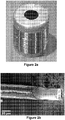
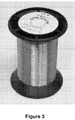
- the metal core diameter varied from 3 to 162 ⁇ m while the total wire diameter (i.e. with glass coating) varied from 5 to 182 ⁇ m.
- the length of the wire produced varied from 28 to 9000 m depending on the stability of the process conditions.
- microwires were measured at room temperature using microscale tensile testing.
- the testing was carried out in a commercial tensile stage made by Ernest Fullam, Inc., which was monitored and controlled by a MTEST Windows software program.
- the deformation was applied by a stepping motor through the gripping system while the load was measured by a load cell that was connected to the end of one gripping jaw.
- Displacement was obtained using a Linear Variable Differential Transformer (LVDT) which was attached to the two gripping jaws to measure the change of gauge length.
- LVDT Linear Variable Differential Transformer
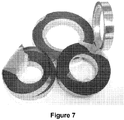
- foils from Alloy 6, Alloy 8, Alloy 9, Alloy 11, and Alloy 12 were produced.
- the foil thickness varied from 22 to 49 ⁇ m
- foil width varied from 6.5 to 50 mm
- the length of the foil produced was ⁇ 100 m to greater than 1 km per run.
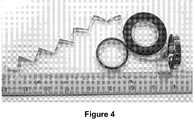
- Bend ability of foils was estimated by corrugation method on 1 m long continuous foil using a custom-built corrugation machine. An image of the foil after corrugation is presented in Figure 13 . All five alloys have demonstrated Type 4 bending behavior with 0 breaks during corrugation deformation (Table 14). Table 14 Results on Bend Ability Testing of Foils Alloy Bend ability Breaks per 1 m 6 Type 4 0 8 Type 4 0 9 Type 4 0 11 Type 4 0 12 Type 4 0
- the mechanical properties of foils were estimated by microhardness measurement and tensile testing. Microhardness testing was performed under a load of 50 g using a M400H1 microhardness tester manufactured by Leco Corporation. Summary of microhardness data is presented in Table 15. As it can be seen, all three alloys have shown average microhardness values in a range from 9.10 to 9.21 GPa. Using a well established relationship where the tensile strength of a material is ⁇ 1/3 of its hardness, the strength level of foil material can be estimated. Expected strength value for all three alloys in foil form is at least 3 GPa.
- Tensile properties of the foils were measured at room temperature using microscale tensile testing.
- the testing was carried out in a commercial tensile stage made by Ernest Fullam, Inc., which was monitored and controlled by a MTEST Windows software program.
- the deformation was applied by a stepping motor through the gripping system while the load was measured by a load cell that was connected to the end of one gripping jaw.
- Displacement was obtained using a Linear Variable Differential Transformer (LVDT) which was attached to the two gripping jaws to measure the change of gauge length.
- Dogbone specimens with gauge length of 9 mm and gauge width of 2 mm were cut by EDM. Before testing, the geometrical parameters of each specimen were carefully measured at least three times at different locations in the gauge length.
- fibers from Alloy 8 were produced.
- the fiber thickness varied from 37 to 53 ⁇ m, with a fiber width from 1.4 to 2.3 mm and lengths from 25 to 30 mm.
- the ability of the fibers to bend completely flat indicates a ductile condition whereby high strain can be obtained but not measured by traditional bend testing.
- 180° bending i.e.
- Type 1 Behavior not bendable without breaking
- Type 2 Behavior bendable on one side with wheel side out (wheel side)
- Type 3 Behavior bendable on one side with free side out (free side)
- Type 4 Behavior bendable on both sides.
- Figure 14 a summary of the 180° bending results as a function of wheel speed during the hyperquenching process is presented.
- Tensile properties of the fibers that exhibited 100% bendability were measured at room temperature using microscale tensile testing.
- the testing was carried out in a commercial tensile stage made by Ernest Fullam, Inc., which was monitored and controlled by a MTEST Windows software program.
- the deformation was applied by a stepping motor through the gripping system while the load was measured by a load cell that was connected to the end of one gripping jaw.
- Displacement was obtained using a Linear Variable Differential Transformer (LVDT) which was attached to the two gripping jaws to measure the change of gauge length.
- LVDT Linear Variable Differential Transformer
- the tensile property values of the commercially produced fibers are lower than that for laboratory produced ribbons from the same alloy (Table 6).
- the main reason for tensile property deviations appears to be due to a large degree of macrodefects ( MD ) in commercially produced fiber that can be clearly seen in Figures 15a and 15b . Formation of these macrodefects appears to be a result of non-optimized hyperquenching process parameters at the initial commercial trial and can be eliminated by further process optimization.
- the cross sectional area is greatly reduced from the average value measured with a micrometer, which leads to anomalously low tensile strength values.
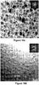
- TEM foils were prepared using mechanical grinding to less than 10 ⁇ m followed by chemo-mechanical polishing. They were then ion milled until perforation using a Gatan Precision Ion Polishing System (PIPS), which was operated at an ion beam energy level of ⁇ 4 keV. TEM observation was carried out in a JOEL 2010 TEM. The TEM micrographs of ribbon microstructures along with the corresponding selected area diffraction patterns in the insets are shown in Figures 16a through 16c .
- PIPS Gatan Precision Ion Polishing System
- the nanoscale structures resulting from spinodal decomposition are interconnected nanoscale phases in a metallic glass matrix which can range in size from several nanometers to ⁇ 100 nm.
- spinodal decomposition in various forms were observed including microconstituent bands, partial decomposition, and full decomposition when uniform and periodic distribution of the crystalline phases in the amorphous matrix is formed. Note that this specific spinodal microconstituent with crystalline spinodally formed phases in an amorphous matrix is representative of the identified SGMM structure.
- microwires from Alloy 3 with metal core diameter of ⁇ 33 ⁇ m, from Alloy 4 with metal core diameter of ⁇ 20 ⁇ m and from Alloy 8 with metal core diameter of ⁇ 20 ⁇ m were produced.
- Samples for TEM analysis were prepared by first preparing a single layer of uniformly aligned microwires array which was then fixed onto a TEM grid with a 2 mm wide slot using very tiny drops of super glue. After curing, the microwires were ion milled in a Gatan Precision Ion Polishing System (PIPS), which was operated at an ion beam energy level of ⁇ 4 keV.
- PIPS Gatan Precision Ion Polishing System
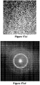
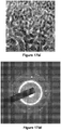
- the ion beam incident angle was 10° first, then reduced to 7° after penetration, and finished up by further reducing the angle to 4° to assure appropriate thin area for TEM examination. Since ion-milling is a slow polishing process in which the material is gradually removed from the currently outmost surface, TEM micrographs obtained from a sharp nanoscale tip illustrate the microstructures at the microwire center. Microstructures observed in the microwires are shown in Figure 17a i , 17b i and 17c i .
- the structure consists of a metallic glass matrix containing a periodic arrangement of clusters which are from 1 to 15 nm thick and 2 to 60 nm long.
- the periodic arrangement of clusters, their shape, and their size are indicative that they formed from a supersaturated glass matrix as a result of a spinodal decomposition.
- the center of microwire has a nanoscale spinodal glass matrix microconstituent structure, which has been frequently observed in melt-spun ribbons of the same alloy.
- the corresponding SAED patterns, shown in Figure 17a ii , 17b ii , 17c ii consist of multiple diffraction rings, including both the first bright amorphous halo of the glass matrix and the crystalline diffraction rings of the clusters.
- the high diffraction intensity of the amorphous halo indicates that the amorphous phase has a relatively large volume fraction forming the matrix phase of microwires.
- the relatively weak diffraction intensities of the crystalline diffraction rings suggest that the nanocrystals are dispersed inside the amorphous matrix.
- foils from Alloy 8 were produced. Samples of less than 10 ⁇ m thin for TEM analysis were prepared using mechanical grinding followed by chemo-mechanical polishing. They were then ion milled until perforation using a Gatan Precision Ion Polishing System (PIPS), which was operated at an ion beam energy level of ⁇ 4 keV. TEM observation was carried out in a JOEL 2010 TEM. The TEM micrograph of the foil microstructure along with the corresponding selected area diffraction pattern are shown in Figures 18a and 18b . The structure consists of a metallic glass matrix containing a periodic arrangement of clusters which are 5 - 30 nm in size.
- PIPS Gatan Precision Ion Polishing System
- the periodic arrangement of clusters, their shape, and their size are indicative that they formed from a supersaturated glass matrix as a result of spinodal decomposition.
- the corresponding SAED pattern suggests that the most of the volume remains amorphous, with semicrystalline clusters that formed and they are in the stage before forming crystals.
- the periodic arrangement of clusters, their shape, and their size are indicative that they formed from a supersaturated glass matrix as a result of spinodal decomposition.
- the corresponding SAED pattern consists of multiple diffraction rings, including both the first bright amorphous halo of the glass matrix and the crystalline diffraction rings of the clusters.
- the high diffraction intensity of the amorphous halo indicates that the amorphous phase has a relatively large volume fraction forming the matrix phase of the fiber.
- a 15 g alloy feedstock of the Alloy 1 was weighed out according to the atomic ratio's provided in Table 1.
- the feedstock material was then placed into the copper hearth of an arc-melting system.
- the feedstock was arc-melted into an ingot using high purity argon as a shielding gas.
- the ingot was flipped and re-melted several times to ensure composition homogeneity.
- the ingot was then cast in the form of a finger approximately 12 mm wide by 30 mm long and 8 mm thick.
- the resulting fingers were then placed in a melt-spinning chamber in a quartz crucible with a hole diameter of ⁇ 0.81 mm.
- a foil from Alloy 1 was produced.
- the foils were tested by 180° bending and the surface of the tested specimen was examined by SEM using an EVO-60 scanning electron microscope manufactured by Carl Zeiss SMT Inc. Typical operating conditions were electron beam energy of 17.5kV, filament current of 2.4 A, and spot size setting of 800.
- Energy Dispersive Spectroscopy was conducted with an Apollo silicon drift detector (SDD-10) using Genesis software both of which are from EDAX. The amplifier time was set to 6.4 micro-sec so that the detector dead time was about 12 -15%. After deformation, high shear band density, or number of shear bands per unit measurement, was observed on the foil surface as shown in Figure 22 .
- fibers from Alloy 8 were produced.
- the fibers were tested by 180° bending and the surface of the tested fibers was examined by SEM using an EVO-60 scanning electron microscope manufactured by Carl Zeiss SMT Inc. Typical operating conditions were electron beam energy of 17.5kV, filament current of 2.4 A, and spot size setting of 800.
- Energy Dispersive Spectroscopy was conducted with an Apollo silicon drift detector (SDD-10) using Genesis software both of which are from EDAX. The amplifier time was set to 6.4 micro-sec so that the detector dead time was about 12 -15%.
- a 15 g alloy feedstock of Alloy 1 was weighed out according to the atomic ratios provided in Table 1.
- the feedstock material was then placed into the copper hearth of an arc-melting system.
- the feedstock was arc-melted into an ingot using high purity argon as a shielding gas.
- the ingot was flipped and re-melted several times to ensure composition homogeneity.
- the ingot was then cast in the form of a finger approximately 12 mm wide by 30 mm long and 8 mm thick.
- the resulting fingers were then placed in a melt-spinning chamber in a quartz crucible with a hole diameter of ⁇ 0.81 mm.
- the ingots were melted using RF induction and then ejected onto a 245 mm diameter copper wheel traveling at a tangential velocity of 10.5 m/s.
- the ribbon was 1.33 mm wide and 0.07 mm thick.
- Melt-spun ribbons were tested in tension and from selected samples TEM foils were prepared from the gauge of tested specimen using mechanical grinding to less than 10 ⁇ m followed by chemo-mechanical polishing. They were then ion milled until perforation using a Gatan Precision Ion Polishing System (PIPS), which was operated at an ion beam energy level of ⁇ 4 keV.
- TEM observation was carried out in a JOEL 2010 TEM.
- LDIC Localized Deformation Induced Changes
- FIG. 26a a TEM micrograph is shown illustrating the ISBB mechanism whereby a shear band oriented ⁇ 40° from the tensile axis ( T ) is observed in the middle of the figure moving from left to right.
- the interaction between the shear band and the SGMM structure is complex and in Figure 26b , the tip of a shear band is shown which clearly illustrates that after the shear band is blunted, long range stress fields are created in the direction of the long axis of the shear band resulting in extended (up to several hundred nm) LDIC occurring beyond the shear transformation zone.
- FIGs 27a and 27b details on the SBAI mechanism can be seen, when two shear bands, after interacting, split into four separate fine branches which are quickly arrested after a short linear distance.
- the SGMM structure has the inherent ability to stop a propagating shear band (ISBB) and that once blunted, shear bands which are subsequently activated through additional stress are arrested through SBAI. It is contemplated that the culmination of these complex interactions then allows for multiple shear banding and global plasticity observed in the studied alloys in different product forms.
- ISBB propagating shear band
- SGMM structure exhibits strain hardening during tensile testing requiring progressively higher force to maintain continuous plastic deformation.
- An example of stress-strain curves for each type of studied product forms are shown in Figure 28 .
- the mechanical properties of the product forms were obtained at room temperature using microscale tensile testing. The testing was carried out in a commercial tensile stage made by Ernest Fullam Inc., which was monitored and controlled by a MTEST Windows software program. The deformation was applied by a stepping motor through the gripping system while the load was measured by a load cell that was connected to the end of one gripping jaw. Displacement was obtained using a Linear Variable Differential Transformer (LVDT) which was attached to the two gripping jaws to measure the change of gauge length.
- LVDT Linear Variable Differential Transformer
- the thickness and width of a tensile specimen was carefully measured at least three times at different locations in the gauge length. The average values were then recorded as gauge thickness and width, and used as input parameters for subsequent stress and strain calculation.
- the initial gauge length for tensile testing was set at ⁇ 7 to ⁇ 9 mm with the exact value determined after the product was fixed, by accurately measuring the span between the front faces of the two gripping jaws. All tests were performed under displacement control, with a strain rate of ⁇ 0.001 s -1 .
- the level of tensile strength and ductility depends on alloy composition, geometrical parameters of product form, quality of produced product (controlled by production process optimization for each alloy) and testing conditions. Nevertheless, as the tensile curves show, after the yield strength is exceeded, typically at 1.0 to 1.5% of elastic strain, the SGMM alloy continues to gain strength until failure regardless the product form and quality. Typically, shear deformation requires dilation and necessitates the creation of free volume which promotes a local decrease in viscosity leading to strain softening and catastrophic failure.
- a microwire from Alloy 3 was produced with a metal core diameter at 20 ⁇ m.
- the microwire was tested in torsion by taking a 40 mm microwire segment and fixing this to a beam.
- a dead load of 1.0 g mass was then attached to the end of the microwire sample which corresponds to a load of ⁇ 32 MPa.
- the resulting torsional load was applied by manually turning the dead load and the total number of turns were counted and used to calculate the shear strain.
- the testing results are presented in Table 18. As shown, the shear strain on breaking is from 5.79 % to 7.03 %.
- the surfaces of the torsion tested microwires were examined in an EVO-60 scanning electron microscope manufactured by Carl Zeiss SMT Inc.
- An Alloy 3 microwire that was tested under unconstrained tension-torsion loading at least three levels of shear bands involving shear band formation, shear band blunting and shear band arresting with existing shear bands, were formed ( Figure 29 ).
- the number of shear bands per linear meter was calculated and was at 2.25 ⁇ 10 6 m -1 . It should be noted that an even higher level of shear banding may be present but not revealed due to the spatial resolution available in the SEM. Thus, the shear band density calculation is conservative.
- the alloy chemistry selection and processing conditions to provide the macroscopic plastic deformation in metallic glass alloys or metallic glass matrix composites result in shear band deformation.
- a shear band with a certain thickness in the range of 10 nm to 100 nm, including all values and ranges therein, is now formed as the result of the focused shear deformation between two neighboring volumes that are separated by the band itself. Since it is a through thickness deformation, the number of shear bands per linear meter that is developed herein may also be quantified and associated with the indicated alloys as the volume fraction of the shear bands in a macroscopically deformed sample.
- the quantification of the number of shear bands per linear unit, such as linear meter, as an additional characteristic installed in the alloys disclosed herein may now be identified when materials are subjected to uniaxial loading conditions when the majority of shear bands are roughly parallel.
- the shear band density may now be quantified as the number of shear bands that are crossed by a linear length in a direction that is locally perpendicular to the shear band traces on the surface.
- the number-per-unit-length definition (m -1 ) can also be applied to shear bands that have a roughly uniform orientation in materials with a thin and wide cross section under uniaxial loading. With more complex stress states such as a uniaxial load with torsion, the shear bands will have multiple orientations and even higher shear band densities which now can be identified using a similar approach.
- shear bands in metallic glasses or metallic glass composite materials may be relatively low.
- failure can occur with the nucleation and resulting propagation of a single shear band with no measurable global plasticity.
- the typical gauge length is in the range from 9 mm to 40 mm, the number of shear bands per linear meter may be understood herein to be from 2.5 ⁇ 10 1 m -1 to 1.1 ⁇ 10 2 m -1 .
- relatively high shear band densities In materials including SGMM structure and the alloy chemistries as identified herein at least two mechanisms have been developed to promote the creation of relatively high shear band densities: ISBB and SBAI. As shown by the case examples above, relatively high number of shear bands per linear meter may be exhibited in the range of 10 5 to 10 6 m -1 upon failure when tensile force is applied at a strain rate of 0.001s -1 . It is contemplated that achieving relatively lower shear band densities in the SGMM structure is also achievable since shear bands are continuously generated after the yield strength is exceeded until failure.
- the shear band density range for the SGMM materials disclosed herein is a shear band density, a number of shear bands per linear meter, of greater than 1.1 ⁇ 10 2 m -1 , such as in the range of 10 2 m -1 to 10 7 m -1 , including all values and ranges therein, in increments of 10 m -1 .
- the present invention relates to the metallic alloy chemistries herein, which are susceptible to SGMM structural formation, together with the ability to undergo ISBB and/or SBAI, to provide shear band densities, a number of shear bands per linear meter, of greater than 1.1 ⁇ 10 2 m -1 to 10 7 m -1 .
Landscapes
- Chemical & Material Sciences (AREA)
- Engineering & Computer Science (AREA)
- Materials Engineering (AREA)
- Mechanical Engineering (AREA)
- Metallurgy (AREA)
- Organic Chemistry (AREA)
- Physics & Mathematics (AREA)
- Thermal Sciences (AREA)
- Crystallography & Structural Chemistry (AREA)
- Continuous Casting (AREA)
- Soft Magnetic Materials (AREA)
- Heat Treatment Of Steel (AREA)
Claims (8)
- Verfahren zum Begünstigen der Erzeugung von relativ hohen Scherbanddichten in einem Band, einer Faser, einer Folie, einem Bahnmaterial und/oder einem Mikrodraht, umfassend die folgenden Schritte:- Zuführen einer Legierungszusammensetzung bestehend aus:vorhandenem Eisen im Bereich von 52 At.-% bis 65 At.-%,vorhandenem Nickel im Bereich von 10 At.-% bis 16,5 At.-%,vorhandenem Bor im Bereich von 13 At.-% bis 15 At.-%,vorhandenem Silizium im Bereich von 0,4 At.-% bis 0,5 At.-%, undvorhandenem Chrom im Bereich von 3 At.-% bis 13,35 At.-%,- Kühlen der Legierung mit einer Rate im Bereich von 103 K/s bis 104 K/s, dadurch Ausbilden von spinodalen Glasmatrix-Mikrobestandteilen in der Legierungszusammensetzung; und- Anlegen einer Zugkraft mit einer Rate von 0,001 s-1; dadurch Ausbilden einer Anzahl von Scherbändern je laufendem Meter im Bereich von größer als 1,1 x 10² m-1 bis 107 m-1.
- Verfahren nach Anspruch 1, wobei die spinodalen Glasmatrix-Mikrobestandteile kristalline oder halbkristalline Cluster mit einer Größe im Bereich von 1 nm bis 15 nm Dicke und 2 nm bis 60 nm Länge umfassen.
- Verfahren nach Anspruch 1, wobei die Legierungszusammensetzung einen Glas-zu-Kristall-Onset bis Peak im Bereich von 395 °C bis 576 °C aufweist, wenn mit einer Rate von 10 °C/min gemessen.
- Verfahren nach Anspruch 1, wobei die Legierungszusammensetzung eine primäre Onset-Glasübergangstemperatur im Bereich von 395 °C bis 505 °C und eine primäre Peak-Glasübergangstemperatur im Bereich von 419 °C bis 521 °C aufweist, wenn mit einer Rate von 10 °C/min gemessen.
- Verfahren nach Anspruch 1, wobei die Legierungszusammensetzung eine Grenzzugfestigkeit im Bereich von 0,62 GPa bis 5,8 GPa aufweist, wenn mit einer Dehnrate von 0,001 s-1 gemessen.
- Verfahren nach Anspruch 1, wobei die Legierungszusammensetzung eine Gesamtdehnung im Bereich von 0,67 % bis 12,8 % aufweist, wenn mit einer Dehnrate von 0,001 s-1 gemessen.
- Verfahren nach Anspruch 11, wobei die Legierungszusammensetzung eine Dicke im Bereich von 0,001 mm bis 3 mm aufweist.
- Verfahren nach Anspruch 1, wobei die Legierungszusammensetzung eine durchschnittliche Mikrohärte im Bereich von 9,10 GPa bis 9,21 GPa aufweist, wenn unter einer 50-Gramm-Last geprüft.
Applications Claiming Priority (2)
| Application Number | Priority Date | Filing Date | Title |
|---|---|---|---|
| US34882310P | 2010-05-27 | 2010-05-27 | |
| PCT/US2011/038425 WO2011150383A2 (en) | 2010-05-27 | 2011-05-27 | Alloys exhibiting spinodal glass matrix microconstituents structure and deformation mechanisms |
Publications (3)
| Publication Number | Publication Date |
|---|---|
| EP2576852A2 EP2576852A2 (de) | 2013-04-10 |
| EP2576852A4 EP2576852A4 (de) | 2017-06-14 |
| EP2576852B1 true EP2576852B1 (de) | 2018-10-31 |
Family
ID=45004881
Family Applications (1)
| Application Number | Title | Priority Date | Filing Date |
|---|---|---|---|
| EP11787532.8A Not-in-force EP2576852B1 (de) | 2010-05-27 | 2011-05-27 | Verfahren zum ausbilden von legierungen mit einer struktur aus spinodalen glasmatrix-mikrobestandteilen und deformationsmechanismen |
Country Status (7)
| Country | Link |
|---|---|
| US (3) | US20110293463A1 (de) |
| EP (1) | EP2576852B1 (de) |
| JP (1) | JP6104795B2 (de) |
| KR (1) | KR101798682B1 (de) |
| CN (1) | CN103228806B (de) |
| CA (1) | CA2800892C (de) |
| WO (1) | WO2011150383A2 (de) |
Families Citing this family (6)
| Publication number | Priority date | Publication date | Assignee | Title |
|---|---|---|---|---|
| US8497027B2 (en) * | 2009-11-06 | 2013-07-30 | The Nanosteel Company, Inc. | Utilization of amorphous steel sheets in honeycomb structures |
| WO2012061282A2 (en) * | 2010-11-02 | 2012-05-10 | The Nanosteel Company, Inc. | Glassy nano-materials |
| US8257512B1 (en) * | 2011-05-20 | 2012-09-04 | The Nanosteel Company, Inc. | Classes of modal structured steel with static refinement and dynamic strengthening and method of making thereof |
| US8419869B1 (en) * | 2012-01-05 | 2013-04-16 | The Nanosteel Company, Inc. | Method of producing classes of non-stainless steels with high strength and high ductility |
| JP6481996B2 (ja) * | 2014-02-17 | 2019-03-13 | 日立金属株式会社 | 高周波加速空胴用磁心、及びその製造方法 |
| CN116018658A (zh) * | 2021-06-25 | 2023-04-25 | 苹果公司 | 用于无线充电系统的纳米晶体结构 |
Family Cites Families (19)
| Publication number | Priority date | Publication date | Assignee | Title |
|---|---|---|---|---|
| US1793529A (en) | 1928-01-04 | 1931-02-24 | Baker & Co Inc | Process and apparatus for making filaments |
| US4439236A (en) * | 1979-03-23 | 1984-03-27 | Allied Corporation | Complex boride particle containing alloys |
| JPS5789450A (en) * | 1980-11-21 | 1982-06-03 | Matsushita Electric Ind Co Ltd | Amorphous magnetic alloy |
| US4515870A (en) * | 1981-07-22 | 1985-05-07 | Allied Corporation | Homogeneous, ductile iron based hardfacing foils |
| US4718475A (en) * | 1984-06-07 | 1988-01-12 | Allied Corporation | Apparatus for casting high strength rapidly solidified magnesium base metal alloys |
| JPS63317645A (ja) * | 1987-03-24 | 1988-12-26 | Nippon Steel Corp | 管状体補強用高耐食性非昌質合金繊維 |
| JP2506267B2 (ja) * | 1993-11-29 | 1996-06-12 | 株式会社東芝 | 高周波用磁心の製造方法 |
| DE10003727A1 (de) * | 2000-01-28 | 2001-08-09 | Siemens Ag | Verfahren zum Herstellen eines Absorberelements |
| JP3611108B2 (ja) * | 2000-05-30 | 2005-01-19 | セイコーエプソン株式会社 | 冷却ロールおよび薄帯状磁石材料 |
| FR2838543B1 (fr) * | 2002-04-12 | 2004-06-04 | Cryptic | Systeme de marquage magnetique, procede et machine pour sa fabrication |
| JP5079498B2 (ja) * | 2004-04-28 | 2012-11-21 | ザ・ナノスティール・カンパニー・インコーポレーテッド | ナノ結晶金属シートの製造方法 |
| EP2294237B1 (de) * | 2008-06-16 | 2017-10-04 | The Nanosteel Company, Inc. | Dehnbare metallgläser |
| JP5728382B2 (ja) | 2008-08-25 | 2015-06-03 | ザ・ナノスティール・カンパニー・インコーポレーテッド | リボン形状の延性金属ガラス |
| KR101624763B1 (ko) * | 2008-10-21 | 2016-05-26 | 더 나노스틸 컴퍼니, 인코포레이티드 | 연성을 보이는 금속성 유리 복합체에 대한 구조 형성의 메커니즘 |
| WO2010053973A1 (en) | 2008-11-04 | 2010-05-14 | The Nanosteel Company, Inc. | Exploitation of deformation mechanisms for industrial usage in thin product forms |
| JP5837824B2 (ja) * | 2009-02-03 | 2015-12-24 | ザ・ナノスティール・カンパニー・インコーポレーテッド | 材料を切断する方法および製品 |
| JP5668074B2 (ja) * | 2009-11-02 | 2015-02-12 | ザ・ナノスティール・カンパニー・インコーポレーテッド | ワイヤおよびワイヤを用いて材料を切断する方法 |
| US8497027B2 (en) * | 2009-11-06 | 2013-07-30 | The Nanosteel Company, Inc. | Utilization of amorphous steel sheets in honeycomb structures |
| JP5931746B2 (ja) * | 2010-02-02 | 2016-06-08 | ザ・ナノスティール・カンパニー・インコーポレーテッド | ガラス状金属組成物の処理における二酸化炭素及び/又は一酸化炭素の気体の利用 |
-
2011
- 2011-05-27 KR KR1020127033172A patent/KR101798682B1/ko not_active Expired - Fee Related
- 2011-05-27 CA CA2800892A patent/CA2800892C/en not_active Expired - Fee Related
- 2011-05-27 US US13/118,035 patent/US20110293463A1/en not_active Abandoned
- 2011-05-27 JP JP2013512056A patent/JP6104795B2/ja not_active Expired - Fee Related
- 2011-05-27 EP EP11787532.8A patent/EP2576852B1/de not_active Not-in-force
- 2011-05-27 WO PCT/US2011/038425 patent/WO2011150383A2/en not_active Ceased
- 2011-05-27 CN CN201180034755.8A patent/CN103228806B/zh not_active Expired - Fee Related
-
2015
- 2015-07-06 US US14/791,879 patent/US20150307973A1/en not_active Abandoned
- 2015-11-30 US US14/953,930 patent/US10266930B2/en not_active Expired - Fee Related
Also Published As
| Publication number | Publication date |
|---|---|
| CA2800892A1 (en) | 2011-12-01 |
| KR101798682B1 (ko) | 2017-11-16 |
| JP6104795B2 (ja) | 2017-03-29 |
| EP2576852A4 (de) | 2017-06-14 |
| CA2800892C (en) | 2019-08-13 |
| US20160304998A1 (en) | 2016-10-20 |
| CN103228806A (zh) | 2013-07-31 |
| US20110293463A1 (en) | 2011-12-01 |
| WO2011150383A3 (en) | 2013-07-18 |
| US20150307973A1 (en) | 2015-10-29 |
| JP2013541632A (ja) | 2013-11-14 |
| WO2011150383A2 (en) | 2011-12-01 |
| EP2576852A2 (de) | 2013-04-10 |
| US10266930B2 (en) | 2019-04-23 |
| KR20130111232A (ko) | 2013-10-10 |
| CN103228806B (zh) | 2015-12-16 |
Similar Documents
| Publication | Publication Date | Title |
|---|---|---|
| US10266930B2 (en) | Alloys exhibiting spinodal glass matrix microconstituents structure and deformation mechanisms | |
| CA2742706C (en) | Exploitation of deformation mechanisms for industrial usage in thin product forms | |
| EP2361320B1 (de) | Strukturbildungsmechanismus für auf metallischem glas basierende verbundwerkstoffe mit duktilität | |
| US8206520B2 (en) | Method of forming ductile metallic glasses in ribbon form | |
| KR102274903B1 (ko) | 슬라브 주조에 의한 금속 강철 제조 | |
| KR101860590B1 (ko) | 비정질 나노-물질 | |
| WO2011097239A1 (en) | Utilization of carbon dioxide and/or carbon monoxide gases in processing metallic glass compositions |
Legal Events
| Date | Code | Title | Description |
|---|---|---|---|
| PUAI | Public reference made under article 153(3) epc to a published international application that has entered the european phase |
Free format text: ORIGINAL CODE: 0009012 |
|
| 17P | Request for examination filed |
Effective date: 20121129 |
|
| AK | Designated contracting states |
Kind code of ref document: A2 Designated state(s): AL AT BE BG CH CY CZ DE DK EE ES FI FR GB GR HR HU IE IS IT LI LT LU LV MC MK MT NL NO PL PT RO RS SE SI SK SM TR |
|
| R17D | Deferred search report published (corrected) |
Effective date: 20130718 |
|
| DAX | Request for extension of the european patent (deleted) | ||
| A4 | Supplementary search report drawn up and despatched |
Effective date: 20170517 |
|
| RIC1 | Information provided on ipc code assigned before grant |
Ipc: C22C 38/10 20060101ALI20170511BHEP Ipc: C22C 38/08 20060101ALI20170511BHEP Ipc: C22C 38/02 20060101ALI20170511BHEP Ipc: C22C 38/54 20060101ALI20170511BHEP Ipc: C22C 38/56 20060101ALI20170511BHEP Ipc: C22C 38/52 20060101ALI20170511BHEP Ipc: C22C 37/10 20060101AFI20170511BHEP Ipc: C22C 38/48 20060101ALI20170511BHEP Ipc: C22C 38/00 20060101ALI20170511BHEP Ipc: C21D 9/52 20060101ALI20170511BHEP Ipc: C22C 38/34 20060101ALI20170511BHEP Ipc: C22C 45/02 20060101ALI20170511BHEP Ipc: C22C 30/00 20060101ALI20170511BHEP |
|
| STAA | Information on the status of an ep patent application or granted ep patent |
Free format text: STATUS: EXAMINATION IS IN PROGRESS |
|
| 17Q | First examination report despatched |
Effective date: 20180124 |
|
| GRAP | Despatch of communication of intention to grant a patent |
Free format text: ORIGINAL CODE: EPIDOSNIGR1 |
|
| STAA | Information on the status of an ep patent application or granted ep patent |
Free format text: STATUS: GRANT OF PATENT IS INTENDED |
|
| INTG | Intention to grant announced |
Effective date: 20180508 |
|
| RIN1 | Information on inventor provided before grant (corrected) |
Inventor name: BRANAGAN, DANIEL, JAMES Inventor name: SERGUEEVA, ALLA Inventor name: ZHOU, JIKOU Inventor name: WALLESER, JASON, K. Inventor name: MEACHAM, BRIAN, E. |
|
| GRAS | Grant fee paid |
Free format text: ORIGINAL CODE: EPIDOSNIGR3 |
|
| GRAA | (expected) grant |
Free format text: ORIGINAL CODE: 0009210 |
|
| STAA | Information on the status of an ep patent application or granted ep patent |
Free format text: STATUS: THE PATENT HAS BEEN GRANTED |
|
| AK | Designated contracting states |
Kind code of ref document: B1 Designated state(s): AL AT BE BG CH CY CZ DE DK EE ES FI FR GB GR HR HU IE IS IT LI LT LU LV MC MK MT NL NO PL PT RO RS SE SI SK SM TR |
|
| REG | Reference to a national code |
Ref country code: CH Ref legal event code: EP Ref country code: GB Ref legal event code: FG4D |
|
| REG | Reference to a national code |
Ref country code: AT Ref legal event code: REF Ref document number: 1059465 Country of ref document: AT Kind code of ref document: T Effective date: 20181115 |
|
| REG | Reference to a national code |
Ref country code: IE Ref legal event code: FG4D |
|
| REG | Reference to a national code |
Ref country code: DE Ref legal event code: R096 Ref document number: 602011053465 Country of ref document: DE |
|
| REG | Reference to a national code |
Ref country code: NL Ref legal event code: MP Effective date: 20181031 |
|
| REG | Reference to a national code |
Ref country code: LT Ref legal event code: MG4D |
|
| REG | Reference to a national code |
Ref country code: AT Ref legal event code: MK05 Ref document number: 1059465 Country of ref document: AT Kind code of ref document: T Effective date: 20181031 |
|
| PG25 | Lapsed in a contracting state [announced via postgrant information from national office to epo] |
Ref country code: NO Free format text: LAPSE BECAUSE OF FAILURE TO SUBMIT A TRANSLATION OF THE DESCRIPTION OR TO PAY THE FEE WITHIN THE PRESCRIBED TIME-LIMIT Effective date: 20190131 Ref country code: HR Free format text: LAPSE BECAUSE OF FAILURE TO SUBMIT A TRANSLATION OF THE DESCRIPTION OR TO PAY THE FEE WITHIN THE PRESCRIBED TIME-LIMIT Effective date: 20181031 Ref country code: BG Free format text: LAPSE BECAUSE OF FAILURE TO SUBMIT A TRANSLATION OF THE DESCRIPTION OR TO PAY THE FEE WITHIN THE PRESCRIBED TIME-LIMIT Effective date: 20190131 Ref country code: PL Free format text: LAPSE BECAUSE OF FAILURE TO SUBMIT A TRANSLATION OF THE DESCRIPTION OR TO PAY THE FEE WITHIN THE PRESCRIBED TIME-LIMIT Effective date: 20181031 Ref country code: LT Free format text: LAPSE BECAUSE OF FAILURE TO SUBMIT A TRANSLATION OF THE DESCRIPTION OR TO PAY THE FEE WITHIN THE PRESCRIBED TIME-LIMIT Effective date: 20181031 Ref country code: ES Free format text: LAPSE BECAUSE OF FAILURE TO SUBMIT A TRANSLATION OF THE DESCRIPTION OR TO PAY THE FEE WITHIN THE PRESCRIBED TIME-LIMIT Effective date: 20181031 Ref country code: IS Free format text: LAPSE BECAUSE OF FAILURE TO SUBMIT A TRANSLATION OF THE DESCRIPTION OR TO PAY THE FEE WITHIN THE PRESCRIBED TIME-LIMIT Effective date: 20190228 Ref country code: LV Free format text: LAPSE BECAUSE OF FAILURE TO SUBMIT A TRANSLATION OF THE DESCRIPTION OR TO PAY THE FEE WITHIN THE PRESCRIBED TIME-LIMIT Effective date: 20181031 Ref country code: AT Free format text: LAPSE BECAUSE OF FAILURE TO SUBMIT A TRANSLATION OF THE DESCRIPTION OR TO PAY THE FEE WITHIN THE PRESCRIBED TIME-LIMIT Effective date: 20181031 Ref country code: FI Free format text: LAPSE BECAUSE OF FAILURE TO SUBMIT A TRANSLATION OF THE DESCRIPTION OR TO PAY THE FEE WITHIN THE PRESCRIBED TIME-LIMIT Effective date: 20181031 |
|
| PG25 | Lapsed in a contracting state [announced via postgrant information from national office to epo] |
Ref country code: SE Free format text: LAPSE BECAUSE OF FAILURE TO SUBMIT A TRANSLATION OF THE DESCRIPTION OR TO PAY THE FEE WITHIN THE PRESCRIBED TIME-LIMIT Effective date: 20181031 Ref country code: AL Free format text: LAPSE BECAUSE OF FAILURE TO SUBMIT A TRANSLATION OF THE DESCRIPTION OR TO PAY THE FEE WITHIN THE PRESCRIBED TIME-LIMIT Effective date: 20181031 Ref country code: GR Free format text: LAPSE BECAUSE OF FAILURE TO SUBMIT A TRANSLATION OF THE DESCRIPTION OR TO PAY THE FEE WITHIN THE PRESCRIBED TIME-LIMIT Effective date: 20190201 Ref country code: RS Free format text: LAPSE BECAUSE OF FAILURE TO SUBMIT A TRANSLATION OF THE DESCRIPTION OR TO PAY THE FEE WITHIN THE PRESCRIBED TIME-LIMIT Effective date: 20181031 Ref country code: PT Free format text: LAPSE BECAUSE OF FAILURE TO SUBMIT A TRANSLATION OF THE DESCRIPTION OR TO PAY THE FEE WITHIN THE PRESCRIBED TIME-LIMIT Effective date: 20190301 Ref country code: NL Free format text: LAPSE BECAUSE OF FAILURE TO SUBMIT A TRANSLATION OF THE DESCRIPTION OR TO PAY THE FEE WITHIN THE PRESCRIBED TIME-LIMIT Effective date: 20181031 |
|
| PG25 | Lapsed in a contracting state [announced via postgrant information from national office to epo] |
Ref country code: IT Free format text: LAPSE BECAUSE OF FAILURE TO SUBMIT A TRANSLATION OF THE DESCRIPTION OR TO PAY THE FEE WITHIN THE PRESCRIBED TIME-LIMIT Effective date: 20181031 Ref country code: DK Free format text: LAPSE BECAUSE OF FAILURE TO SUBMIT A TRANSLATION OF THE DESCRIPTION OR TO PAY THE FEE WITHIN THE PRESCRIBED TIME-LIMIT Effective date: 20181031 Ref country code: CZ Free format text: LAPSE BECAUSE OF FAILURE TO SUBMIT A TRANSLATION OF THE DESCRIPTION OR TO PAY THE FEE WITHIN THE PRESCRIBED TIME-LIMIT Effective date: 20181031 |
|
| PGFP | Annual fee paid to national office [announced via postgrant information from national office to epo] |
Ref country code: DE Payment date: 20190530 Year of fee payment: 9 |
|
| REG | Reference to a national code |
Ref country code: DE Ref legal event code: R097 Ref document number: 602011053465 Country of ref document: DE |
|
| PG25 | Lapsed in a contracting state [announced via postgrant information from national office to epo] |
Ref country code: RO Free format text: LAPSE BECAUSE OF FAILURE TO SUBMIT A TRANSLATION OF THE DESCRIPTION OR TO PAY THE FEE WITHIN THE PRESCRIBED TIME-LIMIT Effective date: 20181031 Ref country code: SK Free format text: LAPSE BECAUSE OF FAILURE TO SUBMIT A TRANSLATION OF THE DESCRIPTION OR TO PAY THE FEE WITHIN THE PRESCRIBED TIME-LIMIT Effective date: 20181031 Ref country code: SM Free format text: LAPSE BECAUSE OF FAILURE TO SUBMIT A TRANSLATION OF THE DESCRIPTION OR TO PAY THE FEE WITHIN THE PRESCRIBED TIME-LIMIT Effective date: 20181031 Ref country code: EE Free format text: LAPSE BECAUSE OF FAILURE TO SUBMIT A TRANSLATION OF THE DESCRIPTION OR TO PAY THE FEE WITHIN THE PRESCRIBED TIME-LIMIT Effective date: 20181031 |
|
| PGFP | Annual fee paid to national office [announced via postgrant information from national office to epo] |
Ref country code: BE Payment date: 20190527 Year of fee payment: 9 |
|
| PLBE | No opposition filed within time limit |
Free format text: ORIGINAL CODE: 0009261 |
|
| STAA | Information on the status of an ep patent application or granted ep patent |
Free format text: STATUS: NO OPPOSITION FILED WITHIN TIME LIMIT |
|
| 26N | No opposition filed |
Effective date: 20190801 |
|
| PG25 | Lapsed in a contracting state [announced via postgrant information from national office to epo] |
Ref country code: SI Free format text: LAPSE BECAUSE OF FAILURE TO SUBMIT A TRANSLATION OF THE DESCRIPTION OR TO PAY THE FEE WITHIN THE PRESCRIBED TIME-LIMIT Effective date: 20181031 |
|
| PGFP | Annual fee paid to national office [announced via postgrant information from national office to epo] |
Ref country code: GB Payment date: 20190528 Year of fee payment: 9 |
|
| REG | Reference to a national code |
Ref country code: CH Ref legal event code: PL |
|
| PG25 | Lapsed in a contracting state [announced via postgrant information from national office to epo] |
Ref country code: CH Free format text: LAPSE BECAUSE OF NON-PAYMENT OF DUE FEES Effective date: 20190531 Ref country code: LI Free format text: LAPSE BECAUSE OF NON-PAYMENT OF DUE FEES Effective date: 20190531 Ref country code: MC Free format text: LAPSE BECAUSE OF FAILURE TO SUBMIT A TRANSLATION OF THE DESCRIPTION OR TO PAY THE FEE WITHIN THE PRESCRIBED TIME-LIMIT Effective date: 20181031 |
|
| PG25 | Lapsed in a contracting state [announced via postgrant information from national office to epo] |
Ref country code: LU Free format text: LAPSE BECAUSE OF NON-PAYMENT OF DUE FEES Effective date: 20190527 |
|
| PG25 | Lapsed in a contracting state [announced via postgrant information from national office to epo] |
Ref country code: TR Free format text: LAPSE BECAUSE OF FAILURE TO SUBMIT A TRANSLATION OF THE DESCRIPTION OR TO PAY THE FEE WITHIN THE PRESCRIBED TIME-LIMIT Effective date: 20181031 |
|
| PG25 | Lapsed in a contracting state [announced via postgrant information from national office to epo] |
Ref country code: IE Free format text: LAPSE BECAUSE OF NON-PAYMENT OF DUE FEES Effective date: 20190527 |
|
| PG25 | Lapsed in a contracting state [announced via postgrant information from national office to epo] |
Ref country code: FR Free format text: LAPSE BECAUSE OF NON-PAYMENT OF DUE FEES Effective date: 20190531 |
|
| REG | Reference to a national code |
Ref country code: DE Ref legal event code: R119 Ref document number: 602011053465 Country of ref document: DE |
|
| REG | Reference to a national code |
Ref country code: BE Ref legal event code: MM Effective date: 20200531 |
|
| GBPC | Gb: european patent ceased through non-payment of renewal fee |
Effective date: 20200527 |
|
| PG25 | Lapsed in a contracting state [announced via postgrant information from national office to epo] |
Ref country code: GB Free format text: LAPSE BECAUSE OF NON-PAYMENT OF DUE FEES Effective date: 20200527 |
|
| PG25 | Lapsed in a contracting state [announced via postgrant information from national office to epo] |
Ref country code: CY Free format text: LAPSE BECAUSE OF FAILURE TO SUBMIT A TRANSLATION OF THE DESCRIPTION OR TO PAY THE FEE WITHIN THE PRESCRIBED TIME-LIMIT Effective date: 20181031 Ref country code: BE Free format text: LAPSE BECAUSE OF NON-PAYMENT OF DUE FEES Effective date: 20200531 Ref country code: DE Free format text: LAPSE BECAUSE OF NON-PAYMENT OF DUE FEES Effective date: 20201201 |
|
| PG25 | Lapsed in a contracting state [announced via postgrant information from national office to epo] |
Ref country code: MT Free format text: LAPSE BECAUSE OF FAILURE TO SUBMIT A TRANSLATION OF THE DESCRIPTION OR TO PAY THE FEE WITHIN THE PRESCRIBED TIME-LIMIT Effective date: 20181031 Ref country code: HU Free format text: LAPSE BECAUSE OF FAILURE TO SUBMIT A TRANSLATION OF THE DESCRIPTION OR TO PAY THE FEE WITHIN THE PRESCRIBED TIME-LIMIT; INVALID AB INITIO Effective date: 20110527 |
|
| PG25 | Lapsed in a contracting state [announced via postgrant information from national office to epo] |
Ref country code: MK Free format text: LAPSE BECAUSE OF FAILURE TO SUBMIT A TRANSLATION OF THE DESCRIPTION OR TO PAY THE FEE WITHIN THE PRESCRIBED TIME-LIMIT Effective date: 20181031 |