EP2577055B1 - Procédé permettant de faire fonctionner une turbine éolienne avec une puissance de sortie améliorée - Google Patents
Procédé permettant de faire fonctionner une turbine éolienne avec une puissance de sortie améliorée Download PDFInfo
- Publication number
- EP2577055B1 EP2577055B1 EP11723238.9A EP11723238A EP2577055B1 EP 2577055 B1 EP2577055 B1 EP 2577055B1 EP 11723238 A EP11723238 A EP 11723238A EP 2577055 B1 EP2577055 B1 EP 2577055B1
- Authority
- EP
- European Patent Office
- Prior art keywords
- wind turbine
- pitch angle
- safety buffer
- power coefficient
- wind
- Prior art date
- Legal status (The legal status is an assumption and is not a legal conclusion. Google has not performed a legal analysis and makes no representation as to the accuracy of the status listed.)
- Active
Links
Images


Classifications
-
- F—MECHANICAL ENGINEERING; LIGHTING; HEATING; WEAPONS; BLASTING
- F03—MACHINES OR ENGINES FOR LIQUIDS; WIND, SPRING, OR WEIGHT MOTORS; PRODUCING MECHANICAL POWER OR A REACTIVE PROPULSIVE THRUST, NOT OTHERWISE PROVIDED FOR
- F03D—WIND MOTORS
- F03D7/00—Controlling wind motors
- F03D7/02—Controlling wind motors the wind motors having rotation axis substantially parallel to the air flow entering the rotor
- F03D7/022—Adjusting aerodynamic properties of the blades
- F03D7/0224—Adjusting blade pitch
-
- F—MECHANICAL ENGINEERING; LIGHTING; HEATING; WEAPONS; BLASTING
- F03—MACHINES OR ENGINES FOR LIQUIDS; WIND, SPRING, OR WEIGHT MOTORS; PRODUCING MECHANICAL POWER OR A REACTIVE PROPULSIVE THRUST, NOT OTHERWISE PROVIDED FOR
- F03D—WIND MOTORS
- F03D7/00—Controlling wind motors
- F03D7/02—Controlling wind motors the wind motors having rotation axis substantially parallel to the air flow entering the rotor
- F03D7/04—Automatic control; Regulation
- F03D7/042—Automatic control; Regulation by means of an electrical or electronic controller
- F03D7/043—Automatic control; Regulation by means of an electrical or electronic controller characterised by the type of control logic
- F03D7/046—Automatic control; Regulation by means of an electrical or electronic controller characterised by the type of control logic with learning or adaptive control, e.g. self-tuning, fuzzy logic or neural network
-
- F—MECHANICAL ENGINEERING; LIGHTING; HEATING; WEAPONS; BLASTING
- F05—INDEXING SCHEMES RELATING TO ENGINES OR PUMPS IN VARIOUS SUBCLASSES OF CLASSES F01-F04
- F05B—INDEXING SCHEME RELATING TO WIND, SPRING, WEIGHT, INERTIA OR LIKE MOTORS, TO MACHINES OR ENGINES FOR LIQUIDS COVERED BY SUBCLASSES F03B, F03D AND F03G
- F05B2270/00—Control
- F05B2270/10—Purpose of the control system
- F05B2270/20—Purpose of the control system to optimise the performance of a machine
-
- F—MECHANICAL ENGINEERING; LIGHTING; HEATING; WEAPONS; BLASTING
- F05—INDEXING SCHEMES RELATING TO ENGINES OR PUMPS IN VARIOUS SUBCLASSES OF CLASSES F01-F04
- F05B—INDEXING SCHEME RELATING TO WIND, SPRING, WEIGHT, INERTIA OR LIKE MOTORS, TO MACHINES OR ENGINES FOR LIQUIDS COVERED BY SUBCLASSES F03B, F03D AND F03G
- F05B2270/00—Control
- F05B2270/30—Control parameters, e.g. input parameters
- F05B2270/328—Blade pitch angle
-
- F—MECHANICAL ENGINEERING; LIGHTING; HEATING; WEAPONS; BLASTING
- F05—INDEXING SCHEMES RELATING TO ENGINES OR PUMPS IN VARIOUS SUBCLASSES OF CLASSES F01-F04
- F05B—INDEXING SCHEME RELATING TO WIND, SPRING, WEIGHT, INERTIA OR LIKE MOTORS, TO MACHINES OR ENGINES FOR LIQUIDS COVERED BY SUBCLASSES F03B, F03D AND F03G
- F05B2270/00—Control
- F05B2270/30—Control parameters, e.g. input parameters
- F05B2270/336—Blade lift measurements
-
- Y—GENERAL TAGGING OF NEW TECHNOLOGICAL DEVELOPMENTS; GENERAL TAGGING OF CROSS-SECTIONAL TECHNOLOGIES SPANNING OVER SEVERAL SECTIONS OF THE IPC; TECHNICAL SUBJECTS COVERED BY FORMER USPC CROSS-REFERENCE ART COLLECTIONS [XRACs] AND DIGESTS
- Y02—TECHNOLOGIES OR APPLICATIONS FOR MITIGATION OR ADAPTATION AGAINST CLIMATE CHANGE
- Y02E—REDUCTION OF GREENHOUSE GAS [GHG] EMISSIONS, RELATED TO ENERGY GENERATION, TRANSMISSION OR DISTRIBUTION
- Y02E10/00—Energy generation through renewable energy sources
- Y02E10/70—Wind energy
- Y02E10/72—Wind turbines with rotation axis in wind direction
Definitions
- the present invention relates to a method for operating a wind turbine, in particular a pitch regulated wind turbine. More particularly, the method of the present invention provides an improved annual energy production of the turbine while reducing the risk of rotor blade stall, and reducing the risk of damage to the wind turbine.
- the pitch angle of the blades is controlled in order to maximise the rotor power coefficient, C P , without exceeding the nominal power coefficient, C P, nom .
- the pitch angle is controlled in such a manner that the power coefficient is as high as possible, and at higher wind speeds, the so-called 'full load' region, the pitch angle is controlled in such a manner that the power coefficient is limited to the nominal power coefficient, C P, nom .
- theoretical curves are used for calculating the pitch angle to be applied under the given circumstances.
- Such curves could, e.g., specify the optimal pitch angle as a function of tip speed ratio, ⁇ , the optimal pitch angle in this context being the pitch angle which provides the highest possible power coefficient, C P .
- the tip speed ratio, ⁇ is the ratio between the blade tip speed and the wind speed.
- the proposed control system consists of two loops: An inner loop for generator torque regulation using adaptive fuzzy control based on variable universe to maximise the capture of power at below-rated wind speed; an outer rotor loop to control pitch angle and keep rated power using least square support vector machine (LS-SVM) control.
- the rotor loop controller input variables are the generator output power, the shaft rotational speed, ⁇ , and the estimated effective wind speed, V w .
- the output control variable is the reference pitch angle, ⁇ ref , of the rotor blades.
- WO2010/057737 describes a method for controlling a wind turbine where an optimal pitch vs. rotational speed curve is selected from group of such curves.
- US2008/001409 describes a wind turbine with a self-learning controller that is configured to optimise the yield parameter of the wind turbine.
- US4339666 describes a blade pitch angle control for a wind turbine generator establishing an optimum power or torque reference signal which, when operating conditions so warrant, is not limited by the nominal torque or power ratings of various turbine generator components.
- US2009/295159 describes a wind turbine control method which is used so that the wind turbine can achieve higher power coefficients.
- US2010/040468 described a method for controlling a wind turbine where the wind turbine is operated above a predetermined wind speed cut-out limit.
- a curve defining optimal pitch angle is initially provided.
- the curve may be 'optimal' in the sense that it defines the pitch angle which, under the given circumstances, e.g. wind conditions, provides the highest possible power output or power coefficient, C P , for the wind turbine.
- the curve may be optimal with respect to other factors or conditions, such as wind direction and/or turbulence. For instance, at some sites it may be known that higher turbulence is present when the wind comes from one direction than when it comes from an opposite direction. In this case, various curves may be selected, depending on a measurement of the wind direction.
- 'pitch' should be interpreted to mean rotation of a wind turbine blade about an axis extending along a longitudinal direction of the wind turbine blade.
- the curve defines the optimal pitch angle as a function of tip speed ratio for the wind turbine blades or as a function of wind speed. Accordingly, the curve may advantageously be an 'optimal pitch' curve as described above.
- the curve may be selected on the basis of site specific data, such as height of the position of the wind turbine, climate, prevailing wind direction, average wind wake conditions, average turbulence conditions, etc.
- part of the optimal pitch angle curve is modified by applying a safety buffer.
- the safety buffer is applied in order to prevent blade stall, and/or that one or more components of the wind turbine are overloaded, in the case of gusts or strong wind shear.
- the safety buffer is normally designed in such a manner that even a 'worst case scenario' can be handled. As described above, the safety buffer therefore will cause the wind turbine to operate in a suboptimal manner, at least in some tip speed ratio or wind speed regions. A safety modified pitch angle curve is thereby obtained.
- the safety buffer may only be applied at tip speed ratios and/or pitch angles where it is known that there is a high risk of the blades stalling and/or that overload is caused to the wind turbine.
- the wind turbine is then operated in accordance with the safety modified pitch angle curve. Thereby the risk of the blades stalling and/or of overload on the wind turbine is eliminated or at least reduced considerably.
- the wind turbine is operated in a suboptimal manner, i.e. the energy production may be lower than the maximum possible energy production.
- the parameter(s) may, e.g., include parameters relating to loads, such as fatigue loads, on blades, bearings and/or tower construction, wind speed, wind shear, turbulence, wind direction, etc.
- the parameter(s) may be measured directly.
- one or more parameters may be measured indirectly in the sense that they are estimated or calculated from measurements of one or more parameters which do not directly provide information regarding wind conditions and/or loads. For instance, loads on the tower construction may be estimated or calculated on the basis of measurements of amplitude and/or frequency of measured tower oscillations.
- the safety buffer is adjusted. Thereby an adjusted pitch angle curve is obtained. Finally, the wind turbine is operated in accordance with the adjusted pitch angle curve.
- the measured parameters represent actual conditions at and/or in the wind turbine. Since the safety buffer is adjusted on the basis of the measured parameters, these actual conditions are taken into account when the final safety buffer is defined. Thus, if the measured parameters indicate that a 'worst case scenario' is not eminent, the safety buffer can be reduced, thereby allowing the wind turbine to be operated closer to the optimal pitch curve, thereby obtaining a power coefficient, C P , which is closer to the maximum power coefficient, C P, max , and increasing the energy production of the wind turbine.
- the safety buffer may be maintained, or even increased, thereby ensuring that blade stall as well as excessive loads are avoided.
- the safety buffer is dynamically updated based on the actual operating conditions.
- the step of adjusting the safety buffer allows the wind turbine to be operated as close to the maximum power coefficient, C P , max , as the actual conditions allow. Thereby the power production of the wind turbine, and thereby the annual energy production, AEP, is increased.
- the step of adjusting the safety buffer could be performed by actually changing the safety buffer and calculating or generating a new pitch curve.
- a number of pre-generated pitch curves may be available, and the step of adjusting the safety buffer may simply be performed by selecting another one of the pre-generated curves, which is more suitable under the given circumstances indicated by the measured parameters.
- the measured parameters are used for calculating an estimated power coefficient, C P, Est .
- the estimated power coefficient, C P, Est is then compared to a reference power coefficient, C P, Ref .
- the reference power coefficient, C P, Ref may advantageously be an optimal power coefficient, C P opt , in which case it may be obtained by measuring the tip speed ratio of the wind turbine and consulting an optimal C P curve.
- the comparison may, e.g., result in an error signal indicating how close the actual power coefficient is to the reference power coefficient.
- the safety buffer is adjusted based on the comparing step.
- the step of adjusting the safety buffer based on the comparing step may be performed in a manner which is expected to decrease the difference between the estimated power coefficient, C P, Est , and the reference power coefficient, C P, Ref .
- the adjustment of the safety buffer brings the actual power coefficient closer to the reference value.
- the step of adjusting the safety buffer based on the comparing step may comprise reducing the safety buffer in the case that the estimated power coefficient, C P, Est , is smaller than the reference power coefficient, C P, Ref .
- the estimated power coefficient, C P, Est is smaller than the reference power coefficient, C P, Ref . It is an indication that the actual operating conditions allow the wind turbine to be operated in a more aggressive manner than it is currently being operated. It is therefore possible to reduce the safety buffer, thereby selecting a more aggressive operating strategy and increasing the power production, without risking that the blades stall and/or that the wind turbine, or one or more components of the wind turbine, is overloaded.
- the step of measuring one or more parameters may comprise measuring an amplitude of an individual and/or cyclic pitch control of the wind turbine blades, and the step of adjusting the safety buffer may be performed on the basis of said measured amplitude.
- the pitch angles of the wind turbine blades may sometimes be controlled in an individual and/or cyclic manner. This may, e.g., be in order to take into account that the wind conditions experienced by a blade varies depending on the angular position of the blade as it rotates along with the rotor. Such variations are, e.g., due to wind shear and tower passage.
- the step of adjusting the safety buffer may comprise the steps of comparing the measured amplitude to a maximum allowable amplitude and reducing the safety buffer in the case that the measured amplitude is smaller than the maximum allowable amplitude.
- the maximum allowable amplitude may advantageously be an amplitude which is expected under the worst possible conditions.
- the safety buffer is, according to this embodiment, reduced if it is established that the actual operating conditions are less severe than the 'worst case scenario'.
- the maximum allowable amplitude may be an amplitude which is expected under conditions which have been assumed when the optimal pitch curve was selected and the safety buffer applied. If it turns out that the actual amplitude is smaller than this, it indicates that the actual conditions are less severe than expected, and the safety buffer can be reduced accordingly.
- At least some of the measured parameters are used for estimating a load on one or more wind turbine components. If it turns out that the estimated load is larger than expected and/or that there is a risk of overload on one or more wind turbine components, it is not safe to reduce the safety buffer. Therefore the original safety buffer is maintained, or the safety buffer may even be increased.
- the step of estimating a load may, e.g., comprise estimating a blade fatigue level.
- loads on tower, bearings, drive train, etc. may be estimated.
- the curve shown in Fig. 1 is theoretically determined in such a manner that for a given tip speed ratio, A, the pitch angle which optimises the power coefficient, C P , is selected.
- the curve is generated in a manner which takes only maximisation of the power production into consideration.
- other relevant parameters such as loads, risk of stall, etc., have not been taken into consideration when generating the curve. Accordingly, if the pitch angle is always controlled along the curve shown in Fig. 1 , the rotor power coefficient, C P , will be optimal, resulting in optimal power production of the wind turbine.
- the pitch angle is controlled in order to maximise the rotor power coefficient, C P .
- This region is sometimes referred to as the 'partial load region'.
- the pitch angle is controlled in order to restrict the power coefficient, C P , to the nominal power coefficient, C P nom .
- This region is sometimes referred to as the 'full load region'. It is clear from Fig. 1 that the pitch angle is generally significantly larger in the full load region than in the partial load region.
- the optimum pitch angle is very low.
- the low pitch angles in this region increases the risk that the wind turbine blade stall if high turbulence is present.
- excessive loads are applied to some wind turbine components, such as blades, bearings, drive train and/or tower in the case of high turbulence or wind shear. Such excessive loads may reduce the expected lifetime of the wind turbine or of one or more components of the wind turbine.
- the pitch angle is normally not controlled in accordance with the optimum pitch curve shown in Fig.
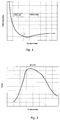
- Fig. 2 is a graph showing optimal power coefficient, C P, opt , as a function of tip speed ratio, ⁇ .
- the curve shown in Fig. 2 illustrates the maximum obtainable power coefficient, C P , for a given tip speed ratio, ⁇ .
- the curve of Fig. 2 is obtained if the pitch angle of the wind turbine is operated in accordance with the curve shown in Fig. 1 .
- the pitch angle is normally not operated precisely in accordance with the curve shown in Fig. 1 for safety reasons. Instead a buffer zone or safety margin is added, at least in the region where the nominal power coefficient, C P nom , is reached, the buffer zone or safety margin causing the applied pitch angle to be larger than the optimum pitch angle, thereby decreasing the power output of the wind turbine.
- the buffer zone or safety margin is selected in such a manner that there is no risk that the blades stall or that the components of the wind turbine experience excessive loads, even if the worst possible conditions, in terms of turbulence, gusts and/or wind shear, should occur.
- the actual wind conditions are examined and evaluated, and in the case that it is revealed that the severity of the actual wind conditions is far from the worst possible conditions, then the safety criteria are loosened, the buffer zone or safety margin is reduced, and the pitch angle is controlled to be closer to the optimal pitch curve shown in Fig. 1 . If, on the other hand, it is revealed that the severity of the actual wind conditions is close to the worst possible conditions, then the original buffer zone or safety margin is maintained. Furthermore, in the case that it is revealed that the severity of the actual wind conditions is worse than expected and accounted for in the buffer zone or safety margin, then the buffer zone or safety margin may be increased, thereby reducing the risk of blade stall or that excessive loads are applied to the components of the wind turbine.
- Fig. 3 is a graph showing pitch angle as a function of tip speed ratio, ⁇ , similar to Fig. 1 .
- the full line 1 illustrates a reference curve, i.e. an optimal pitch curve including a full buffer zone or safety margin as described above.
- the dashed line 2 represents a more aggressive control strategy, where the buffer zone or safety margin is decreased in the case that it is revealed that the severity of the actual wind conditions is far from the worst possible conditions.
- the dashed line 2 represents a control strategy according to an embodiment of the invention.
- Fig. 4 is a graph showing rotor power coefficient, C P , as a function of tip speed ratio, A, similar to Fig. 2 .
- the full line 3 represents the power coefficient, C P , obtained when the pitch angle is controlled in accordance with the reference control strategy illustrated by curve 1 of Fig. 3
- the dashed line 4 represents the power coefficient, C P , obtained when the pitch angle is controlled in accordance with the control strategy of the invention illustrated by curve 2 of Fig. 3 .
- the aggressive control strategy 4 results in a significantly higher power coefficient, C P , than the reference control strategy 3, over a wide range of tip speed ratios, ⁇ .
- a significant increase in the annual energy production of the wind turbine is obtained, without increasing the risk that the wind turbine blades stall or that excessive loads are applied to the components of the wind turbine.
- Fig. 5 is a flow diagram illustrating a method according to an embodiment of the invention.
- the parameter values may, e.g., include tip speed ratio, output power, pitch angle, yaw error, wind speed, rotational speed of the generator, temperature and height of the location of the wind turbine.
- the parameter values may be measured directly.
- one or more of the parameter values may be estimated or calculated from measured values. For instance, loads or turbulence may be estimated on the basis of measured parameters, and the estimated loads or turbulence may be used when adjusting the pitch angle.
- measured and/or estimated parameters may be used for calculating and/or estimating quantities which are required for pitch angle adjustment, e.g. C P , loads, turbulence, etc.
- a reference pitch angle can be selected at step 6.
- the reference pitch angle is selected by means of a reference pitch curve including a buffer zone or safety margin as described above with reference to Fig. 3 .
- C P estimator Some or all of the measured parameter values are supplied to a C P estimator, and in step 7 an estimated value, C P Est , of the actual current rotor power coefficient, C P , of the wind turbine is calculated on the basis of the measured parameter values, and possibly on the basis of one or more estimated values. Simultaneously, a reference C P value is obtained on the basis of the measured tip speed ratio and by means of a maximum C P reference curve. The reference C P value, C P ref , and the estimate C P value, C P est , are compared in step 8, thereby obtaining an error signal, C P error .
- step 9 it is investigated whether C P error is smaller than a threshold value. If this not is the case, i.e. if the error signal, C P error , is large and positive, a C P compensation is calculated, and the pitch angle is decreased in step 10. Thus, in this case a pitch angle which is smaller than the pitch angle specified by the reference pitch curve is selected. Exactly how much the pitch angle is to be adjusted is carefully calculated, depending on the size of the error signal, C P error . Furthermore, it should be noted that other considerations may be taken into account when adjusting the pitch angle. For instance, measured, estimated or calculated loads, blade stall, outputs from other controllers, etc. may be incorporated when the pitch adjustment is calculated.
- step 9 the process is advanced to step 11, where it is investigated whether C P error is smaller than zero. If this is not the case, i.e. in the case that the error signal, C P error , is equal to or close to zero, the reference pitch angle is maintained as shown in step 12.
- step 13 the pitch angle is increased in step 13.
- a larger pitch angle than the one specified by the reference pitch curve is selected, since this is an indication that the actual wind conditions are more severe than expected.
- the method may further comprise calculating an estimated value of the fatigue on the blades under the given operating conditions. Based on the estimated blade fatigue, a lower limit for the pitch angle may be calculated, the lower limit representing a pitch angle below which it must be expected that excessive loads are applied to the blades. According to one embodiment, the adjustment of the pitch angle described above, based on the error signal, C P error , is not allowed to decrease the pitch angle below the calculated lower limit.
- the pitch angles of the blades may be controlled in an individual and/or cyclic manner in order to reduce the loads on the blades, bearings, drive train, tower, etc., e.g. due to wind shear, gusts or turbulence.
- This is normally obtained by applying a correction to the pitch angle of each blade, the correction varying cyclically depending on the angular position of the blade.
- the correction may be calculated on the basis of measured parameter values representing the actual wind conditions at the wind turbine site.
- the amplitude of the cyclically varying corrections is a measure for the current wind shear.
- the buffer zone or safety margin applied to the optimal pitch curve may, among other things, be established on the basis of a maximum expected amplitude of the cyclic variations.
- the actual amplitude of the cyclic variations may be measured, and this measured amplitude may be compared to the maximum expected amplitude. In the case that the comparison reveals that the actual amplitude is much smaller than the maximum expected amplitude, then the buffer zone or safety margin may be reduced accordingly, thereby allowing a smaller pitch angle and a more aggressive control strategy.
Landscapes
- Engineering & Computer Science (AREA)
- Mechanical Engineering (AREA)
- Combustion & Propulsion (AREA)
- General Engineering & Computer Science (AREA)
- Sustainable Development (AREA)
- Sustainable Energy (AREA)
- Chemical & Material Sciences (AREA)
- Life Sciences & Earth Sciences (AREA)
- Physics & Mathematics (AREA)
- Evolutionary Computation (AREA)
- Artificial Intelligence (AREA)
- Fluid Mechanics (AREA)
- Fuzzy Systems (AREA)
- Mathematical Physics (AREA)
- Software Systems (AREA)
- Wind Motors (AREA)
Claims (8)
- Procédé pour mettre en luvre une éolienne, l'éolienne comprenant un rotor ayant un ensemble de pales d'éolienne, ledit rotor étant monté sur un mât, le procédé comprenant les étapes de :- fourniture d'une courbe définissant un angle de calage optimal comme une fonction du rapport de vitesse périphérique pour les pales d'éolienne ou comme une fonction de la vitesse du vent, l'angle de calage optimal étant l'angle de calage qui, sous des conditions de vent données, fournit la sortie de puissance ou le coefficient de puissance, CP, pour l'éolienne, le plus élevé possible- modification seulement d'une partie de ladite courbe d'angle de calage optimal en appliquant une réserve de sécurité, obtenant de ce fait une courbe d'angle de calage modifiée de sécurité, la réserve de sécurité étant appliquée afin empêcher la pale d'être immobilisée, et/ou qu'un ou plusieurs composants de l'éolienne soient surchargés,- mise en luvre de l'éolienne selon la courbe d'angle de calage modifiée de sécurité,- mesure d'un ou de plusieurs paramètres fournissant des informations quant aux conditions de vent et/ou de charges sur un ou plusieurs composants de l'éolienne, pendant le fonctionnement de l'éolienne,- réglage de la réserve de sécurité, en se basant sur lesdites mesures, obtenant de ce fait une courbe d'angle de calage ajustée, et- mise en luvre de l'éolienne selon la courbe d'angle de calage ajustée.
- Procédé selon la revendication 1, dans lequel l'étape de réglage de la réserve de sécurité comprend :- le calcul d'un coefficient de puissance évalué, CP, Est,- la comparaison du coefficient de puissance évalué, CP, Est, à un coefficient de puissance de référence, CP, Ref, et- le réglage de la réserve de sécurité en se basant sur l'étape de comparaison.
- Procédé selon la revendication 2, dans lequel l'étape de réglage de la réserve de sécurité en se basant sur l'étape de comparaison est effectuée d'une manière qui est attendue pour diminuer la différence entre le coefficient de puissance évalué, CP, Est et le coefficient de puissance de référence, CP, Ref.
- Procédé selon la revendication 2 ou 3, dans lequel l'étape de réglage de la réserve de sécurité en se basant sur l'étape de comparaison comprend la réduction de la réserve de sécurité dans le cas où le coefficient de puissance évalué, CP, Est, est plus petit que le coefficient de puissance de référence, CP, Ref.
- Procédé selon n'importe laquelle des revendications précédentes, dans lequel l'étape de mesure d'un ou plusieurs paramètres comprend la mesure d'une amplitude d'une commande de pas individuel et/ou cyclique des pales d'éolienne et dans lequel l'étape de réglage de la réserve de sécurité est effectuée sur la base de ladite amplitude mesurée.
- Procédé selon la revendication 5, dans lequel l'étape de réglage de la réserve de sécurité comprend les étapes de comparaison de l'amplitude mesurée à une amplitude admissible maximale et de réduction de la réserve de sécurité dans le cas où l'amplitude mesurée est plus petite que l'amplitude admissible maximale.
- Procédé selon n'importe laquelle des revendications précédentes, dans lequel l'étape de réglage de la réserve de sécurité comprend :- l'évaluation d'une charge sur un ou plusieurs composants d'éolienne sur la base d'un ou plusieurs des paramètres mesurés, et- le maintien ou l'augmentation de la réserve de sécurité dans le cas où la charge évaluée dépasse une valeur de seuil prédéterminée.
- Procédé selon la revendication 7, dans lequel l'étape d'évaluation d'une charge comprend l'évaluation d'un niveau de fatigue de pale.
Applications Claiming Priority (3)
| Application Number | Priority Date | Filing Date | Title |
|---|---|---|---|
| US35058110P | 2010-06-02 | 2010-06-02 | |
| DKPA201070236 | 2010-06-02 | ||
| PCT/DK2011/050183 WO2011150931A2 (fr) | 2010-06-02 | 2011-05-31 | Procédé permettant de faire fonctionner une turbine éolienne avec une puissance de sortie améliorée |
Publications (3)
| Publication Number | Publication Date |
|---|---|
| EP2577055A2 EP2577055A2 (fr) | 2013-04-10 |
| EP2577055B1 true EP2577055B1 (fr) | 2016-06-29 |
| EP2577055B8 EP2577055B8 (fr) | 2016-10-12 |
Family
ID=44626701
Family Applications (1)
| Application Number | Title | Priority Date | Filing Date |
|---|---|---|---|
| EP11723238.9A Active EP2577055B8 (fr) | 2010-06-02 | 2011-05-31 | Procédé permettant de faire fonctionner une turbine éolienne avec une puissance de sortie améliorée |
Country Status (4)
| Country | Link |
|---|---|
| US (1) | US9261076B2 (fr) |
| EP (1) | EP2577055B8 (fr) |
| ES (1) | ES2589384T3 (fr) |
| WO (1) | WO2011150931A2 (fr) |
Families Citing this family (46)
| Publication number | Priority date | Publication date | Assignee | Title |
|---|---|---|---|---|
| AU2009265828B2 (en) * | 2008-06-30 | 2014-05-22 | Vestas Wind Systems A/S | Power curtailment of wind turbines |
| US8858174B2 (en) * | 2011-05-12 | 2014-10-14 | General Electric Company | Wind turbine torque-speed control |
| TWI445276B (zh) * | 2011-10-04 | 2014-07-11 | Iner Aec Executive Yuan | 一種整合自動電壓調整器之控制系統和方法 |
| US9683551B2 (en) * | 2011-12-29 | 2017-06-20 | Vestas Wind Systems A/S | Optimization of power production in a wind turbine at below rated power |
| CN102536654A (zh) * | 2012-02-07 | 2012-07-04 | 国电联合动力技术有限公司 | 一种变速恒频风力机切入阶段的变桨控制方法 |
| US20130259682A1 (en) * | 2012-03-27 | 2013-10-03 | General Electric Company | Method of rotor-stall prevention in wind turbines |
| CN102797631B (zh) * | 2012-08-24 | 2014-05-14 | 国电联合动力技术有限公司 | 一种风电机组的最优增益在线自校正方法、系统及其装置 |
| WO2014048583A1 (fr) * | 2012-09-28 | 2014-04-03 | Siemens Aktiengesellschaft | Procédé et agencement permettant de commander une éolienne |
| EP2719895B1 (fr) * | 2012-10-09 | 2017-07-26 | GE Renewable Technologies | Procédé de supervision d'une éolienne |
| US10001108B2 (en) | 2013-01-09 | 2018-06-19 | General Electric Company | Method and apparatus for operating a wind turbine with a variable speed limit that may be above or below a predetermined speed limit depending on whether there is an estimated detrimental overspeed state |
| US9347430B2 (en) * | 2013-04-12 | 2016-05-24 | King Fahd University Of Petroleum And Minerals | Adaptive pitch control system for wind generators |
| US9835135B2 (en) | 2013-10-31 | 2017-12-05 | General Electric Company | System and method for controlling a wind turbine |
| CN103590973B (zh) * | 2013-11-23 | 2015-12-30 | 大连尚能科技发展有限公司 | 一种应用于风力发电机组大风工况下的变桨控制方法 |
| WO2015192856A1 (fr) * | 2014-06-19 | 2015-12-23 | Vestas Wind Systems A/S | Commande d'éoliennes en réponse au cisaillement du vent |
| EP3221581B1 (fr) | 2014-11-21 | 2020-10-28 | Vestas Wind Systems A/S | Procédé pour estimer une vitesse du vent d'une manière stable |
| CN107850044B (zh) | 2015-06-30 | 2020-02-07 | 维斯塔斯风力系统集团公司 | 用于风力涡轮机的保护的控制方法和系统 |
| CN105257471B (zh) * | 2015-10-23 | 2018-03-23 | 北京金风科创风电设备有限公司 | 风力发电机组桨距角控制方法、装置及系统 |
| TWI582563B (zh) * | 2015-12-17 | 2017-05-11 | 遠東科技大學 | 風機控制裝置及其控制方法 |
| WO2017108044A1 (fr) * | 2015-12-23 | 2017-06-29 | Vestas Wind Systems A/S | Commande de turbines éoliennes en fonction d'estimations de fiabilité |
| CN108150360A (zh) * | 2016-12-05 | 2018-06-12 | 北京金风科创风电设备有限公司 | 检测风电机组的等效载荷的方法和设备 |
| ES2942017T3 (es) * | 2018-01-09 | 2023-05-29 | Vestas Wind Sys As | Un método para controlar un parque de energía eólica teniendo en cuenta efectos de estela |
| DE102018100727A1 (de) * | 2018-01-15 | 2019-07-18 | Wobben Properties Gmbh | Verfahren zum Steuern einer Windenergieanlage und Windenergieanlage |
| CN112055782B (zh) * | 2018-05-03 | 2023-10-31 | 通用电气公司 | 用于控制风力涡轮转子叶片的桨距角的系统和方法 |
| DE102018113706A1 (de) | 2018-06-08 | 2019-12-12 | Wobben Properties Gmbh | Verfahren zum Betreiben einer Windenergieanlage, Windenergieanlage und Windpark |
| US11261845B2 (en) * | 2018-07-26 | 2022-03-01 | General Electric Company | System and method for protecting wind turbines during extreme wind direction change |
| CN110761945B (zh) * | 2018-07-27 | 2020-11-03 | 北京金风科创风电设备有限公司 | 风力发电机组的叶片失速控制方法及装置 |
| US10605228B2 (en) | 2018-08-20 | 2020-03-31 | General Electric Company | Method for controlling operation of a wind turbine |
| CN111271179B (zh) * | 2018-12-04 | 2022-07-05 | 中国航空工业集团公司金城南京机电液压工程研究中心 | 一种冲压空气涡轮的功率性能试验方法 |
| CN111765045B (zh) * | 2019-04-01 | 2022-09-06 | 北京金风科创风电设备有限公司 | 风力发电机组的控制方法及装置 |
| US12006914B2 (en) | 2019-06-27 | 2024-06-11 | Vestas Wind Systems A/S | Controlling power output of a wind turbine at below-rated wind speed |
| US11060504B1 (en) | 2020-02-07 | 2021-07-13 | General Electric Company | Systems and methods for continuous machine learning based control of wind turbines |
| CN111336062B (zh) * | 2020-03-05 | 2021-11-09 | 中国大唐集团科学技术研究院有限公司华中电力试验研究院 | 一种基于测量风速的风力发电机组最大风能捕获方法 |
| CN114076060B (zh) * | 2020-08-13 | 2023-09-12 | 金风科技股份有限公司 | 叶片失速条件下桨距角自动寻优的方法及设备 |
| US11231012B1 (en) | 2020-09-22 | 2022-01-25 | General Electric Renovables Espana, S.L. | Systems and methods for controlling a wind turbine |
| CN114607556B (zh) * | 2020-12-09 | 2024-09-24 | 金风科技股份有限公司 | 用于风力发电机组的控制方法及装置 |
| CN114673630B (zh) * | 2020-12-24 | 2025-01-28 | 金风科技股份有限公司 | 风电机组叶尖速比的确定方法、装置、主控制器 |
| US11649804B2 (en) | 2021-06-07 | 2023-05-16 | General Electric Renovables Espana, S.L. | Systems and methods for controlling a wind turbine |
| US12180936B2 (en) | 2021-07-28 | 2024-12-31 | General Electric Renovables Espana, S.L. | Systems and methods for operating a wind farm |
| CN113638851B (zh) * | 2021-08-04 | 2022-11-11 | 浙江运达风电股份有限公司 | 一种用于风力发电机组失速监测的方法 |
| CN114294155B (zh) * | 2021-11-11 | 2024-12-06 | 华能新能源股份有限公司 | 风电机组有功功率控制方法及装置 |
| CN114352476B (zh) * | 2021-12-30 | 2025-01-24 | 上海电机学院 | 一种基于svm分区权系数分配的风机独立变桨控制方法 |
| CN114517763B (zh) * | 2022-01-10 | 2025-06-17 | 明阳智慧能源集团股份公司 | 大容量变速风力发电机组提升发电量的控制方法与系统 |
| CN114856931B (zh) * | 2022-03-30 | 2025-07-08 | 许昌许继风电科技有限公司 | 一种风电机组疲劳载荷评估方法、系统及电子设备 |
| CN114542378B (zh) * | 2022-04-26 | 2022-07-12 | 东方电气风电股份有限公司 | 一种动态计算风力发电机组最优最小桨角的方法 |
| CN116498490B (zh) * | 2023-04-27 | 2024-05-24 | 中国船级社质量认证有限公司 | 一种风电机组变桨控制方法及系统 |
| CN117028151A (zh) * | 2023-09-12 | 2023-11-10 | 国电南京自动化股份有限公司 | 一种基于风速风向动态变化的风电机组桨距角控制方法 |
Family Cites Families (6)
| Publication number | Priority date | Publication date | Assignee | Title |
|---|---|---|---|---|
| US4339666A (en) | 1980-12-24 | 1982-07-13 | United Technologies Corporation | Blade pitch angle control for a wind turbine generator |
| EP1230479B1 (fr) * | 1999-11-03 | 2004-09-01 | Vestas Wind Systems A/S | Procede pour commander le fonctionnement d'une eolienne et eolienne utilisee dans ce procede |
| EP2035899A1 (fr) * | 2006-04-26 | 2009-03-18 | Alliance for Sustainable Energy, LLC | Commande de pas adaptative pour turbines eoliennes a vitesse variable |
| US7560823B2 (en) | 2006-06-30 | 2009-07-14 | General Electric Company | Wind energy system and method of operation thereof |
| WO2008131776A2 (fr) * | 2007-04-30 | 2008-11-06 | Vestas Wind Systems A/S | Procédé d'exploitation d'une éolienne, éolienne et groupe d'éolienne |
| US8712593B2 (en) * | 2008-11-18 | 2014-04-29 | Vestas Wind Systems A/S | Method for controlling operation of a wind turbine |
-
2011
- 2011-05-31 US US13/701,259 patent/US9261076B2/en not_active Expired - Fee Related
- 2011-05-31 WO PCT/DK2011/050183 patent/WO2011150931A2/fr not_active Ceased
- 2011-05-31 ES ES11723238.9T patent/ES2589384T3/es active Active
- 2011-05-31 EP EP11723238.9A patent/EP2577055B8/fr active Active
Also Published As
| Publication number | Publication date |
|---|---|
| WO2011150931A2 (fr) | 2011-12-08 |
| WO2011150931A3 (fr) | 2012-03-29 |
| US9261076B2 (en) | 2016-02-16 |
| EP2577055B8 (fr) | 2016-10-12 |
| ES2589384T3 (es) | 2016-11-14 |
| EP2577055A2 (fr) | 2013-04-10 |
| US20130140819A1 (en) | 2013-06-06 |
Similar Documents
| Publication | Publication Date | Title |
|---|---|---|
| EP2577055B1 (fr) | Procédé permettant de faire fonctionner une turbine éolienne avec une puissance de sortie améliorée | |
| US8128362B2 (en) | Method of operating a wind turbine, a wind turbine and a cluster of wind turbines | |
| CN107667220B (zh) | 考虑疲劳量度的风力涡轮机控制 | |
| US7948104B2 (en) | Method of operating a wind turbine with pitch control, a wind turbine and a cluster of wind turbines | |
| US8979492B2 (en) | Methods and systems for determining a pitch angle offset signal and for controlling a rotor frequency of a rotor of a wind turbine for speed avoidance control | |
| US9970413B2 (en) | Wind turbine with a load controller | |
| US8803351B2 (en) | Control method for a wind turbine | |
| US8793027B2 (en) | Power curtailment of wind turbines | |
| US9835134B2 (en) | Method and computing module for determining pitch angle adjustment signals of a wind turbine based on the maximum rotational speed | |
| US11815066B2 (en) | Method for operating a wind turbine, controller, wind turbine and wind farm | |
| US20130177418A1 (en) | Method for adjusting the rotational speed of a wind turbine and wind turbine | |
| CN101031720A (zh) | 用来调节风能设备的方法和风能设备 | |
| EP2647838B1 (fr) | Procédé pour faire fonctionner une éolienne comportant un moyeu de rotor supportant au moins une pale de rotor | |
| US20170218923A1 (en) | Wind turbine power generating apparatus and method of operating the same | |
| CN101784791A (zh) | 控制风力发电机中至少一个调节机构的方法、风力发电机以及风力发电站 | |
| RU2729587C1 (ru) | Ветроэнергетическая установка и способ эксплуатации ветроэнергетической установки | |
| EP3085955A1 (fr) | Procédé de contrôle du fonctionnement d'une éolienne | |
| US20200072192A1 (en) | Method for controlling a wind turbine | |
| US20110037263A1 (en) | Blade angle adjustment rate limit adjustment | |
| EP3436696B1 (fr) | Procédé de commande pour une turbine éolienne | |
| CN115370529A (zh) | 用于控制风能设施的方法、风能设施和风电场 | |
| JP4394422B2 (ja) | 水平軸風車及びその制御方法 | |
| JP2020193565A (ja) | 風力発電装置とその制御方法 |
Legal Events
| Date | Code | Title | Description |
|---|---|---|---|
| PUAI | Public reference made under article 153(3) epc to a published international application that has entered the european phase |
Free format text: ORIGINAL CODE: 0009012 |
|
| 17P | Request for examination filed |
Effective date: 20121220 |
|
| AK | Designated contracting states |
Kind code of ref document: A2 Designated state(s): AL AT BE BG CH CY CZ DE DK EE ES FI FR GB GR HR HU IE IS IT LI LT LU LV MC MK MT NL NO PL PT RO RS SE SI SK SM TR |
|
| DAX | Request for extension of the european patent (deleted) | ||
| GRAP | Despatch of communication of intention to grant a patent |
Free format text: ORIGINAL CODE: EPIDOSNIGR1 |
|
| INTG | Intention to grant announced |
Effective date: 20160216 |
|
| GRAS | Grant fee paid |
Free format text: ORIGINAL CODE: EPIDOSNIGR3 |
|
| GRAA | (expected) grant |
Free format text: ORIGINAL CODE: 0009210 |
|
| AK | Designated contracting states |
Kind code of ref document: B1 Designated state(s): AL AT BE BG CH CY CZ DE DK EE ES FI FR GB GR HR HU IE IS IT LI LT LU LV MC MK MT NL NO PL PT RO RS SE SI SK SM TR |
|
| REG | Reference to a national code |
Ref country code: GB Ref legal event code: FG4D |
|
| REG | Reference to a national code |
Ref country code: CH Ref legal event code: EP |
|
| REG | Reference to a national code |
Ref country code: AT Ref legal event code: REF Ref document number: 809320 Country of ref document: AT Kind code of ref document: T Effective date: 20160715 |
|
| REG | Reference to a national code |
Ref country code: IE Ref legal event code: FG4D |
|
| RAP2 | Party data changed (patent owner data changed or rights of a patent transferred) |
Owner name: VESTAS WIND SYSTEMS A/S |
|
| REG | Reference to a national code |
Ref country code: DE Ref legal event code: R096 Ref document number: 602011027736 Country of ref document: DE |
|
| RAP2 | Party data changed (patent owner data changed or rights of a patent transferred) |
Owner name: VESTAS WIND SYSTEMS A/S |
|
| REG | Reference to a national code |
Ref country code: DE Ref legal event code: R081 Ref document number: 602011027736 Country of ref document: DE Owner name: VESTAS WIND SYSTEMS A/S, DK Free format text: FORMER OWNER: VESTAS WIND SYSTEMS A/S, RANDERS, DK |
|
| REG | Reference to a national code |
Ref country code: LT Ref legal event code: MG4D |
|
| PG25 | Lapsed in a contracting state [announced via postgrant information from national office to epo] |
Ref country code: NO Free format text: LAPSE BECAUSE OF FAILURE TO SUBMIT A TRANSLATION OF THE DESCRIPTION OR TO PAY THE FEE WITHIN THE PRESCRIBED TIME-LIMIT Effective date: 20160929 Ref country code: LT Free format text: LAPSE BECAUSE OF FAILURE TO SUBMIT A TRANSLATION OF THE DESCRIPTION OR TO PAY THE FEE WITHIN THE PRESCRIBED TIME-LIMIT Effective date: 20160629 Ref country code: FI Free format text: LAPSE BECAUSE OF FAILURE TO SUBMIT A TRANSLATION OF THE DESCRIPTION OR TO PAY THE FEE WITHIN THE PRESCRIBED TIME-LIMIT Effective date: 20160629 |
|
| REG | Reference to a national code |
Ref country code: NL Ref legal event code: MP Effective date: 20160629 |
|
| REG | Reference to a national code |
Ref country code: ES Ref legal event code: FG2A Ref document number: 2589384 Country of ref document: ES Kind code of ref document: T3 Effective date: 20161114 |
|
| PG25 | Lapsed in a contracting state [announced via postgrant information from national office to epo] |
Ref country code: HR Free format text: LAPSE BECAUSE OF FAILURE TO SUBMIT A TRANSLATION OF THE DESCRIPTION OR TO PAY THE FEE WITHIN THE PRESCRIBED TIME-LIMIT Effective date: 20160629 Ref country code: GR Free format text: LAPSE BECAUSE OF FAILURE TO SUBMIT A TRANSLATION OF THE DESCRIPTION OR TO PAY THE FEE WITHIN THE PRESCRIBED TIME-LIMIT Effective date: 20160930 Ref country code: LV Free format text: LAPSE BECAUSE OF FAILURE TO SUBMIT A TRANSLATION OF THE DESCRIPTION OR TO PAY THE FEE WITHIN THE PRESCRIBED TIME-LIMIT Effective date: 20160629 Ref country code: RS Free format text: LAPSE BECAUSE OF FAILURE TO SUBMIT A TRANSLATION OF THE DESCRIPTION OR TO PAY THE FEE WITHIN THE PRESCRIBED TIME-LIMIT Effective date: 20160629 Ref country code: SE Free format text: LAPSE BECAUSE OF FAILURE TO SUBMIT A TRANSLATION OF THE DESCRIPTION OR TO PAY THE FEE WITHIN THE PRESCRIBED TIME-LIMIT Effective date: 20160629 Ref country code: NL Free format text: LAPSE BECAUSE OF FAILURE TO SUBMIT A TRANSLATION OF THE DESCRIPTION OR TO PAY THE FEE WITHIN THE PRESCRIBED TIME-LIMIT Effective date: 20160629 |
|
| REG | Reference to a national code |
Ref country code: AT Ref legal event code: MK05 Ref document number: 809320 Country of ref document: AT Kind code of ref document: T Effective date: 20160629 |
|
| PG25 | Lapsed in a contracting state [announced via postgrant information from national office to epo] |
Ref country code: RO Free format text: LAPSE BECAUSE OF FAILURE TO SUBMIT A TRANSLATION OF THE DESCRIPTION OR TO PAY THE FEE WITHIN THE PRESCRIBED TIME-LIMIT Effective date: 20160629 Ref country code: CZ Free format text: LAPSE BECAUSE OF FAILURE TO SUBMIT A TRANSLATION OF THE DESCRIPTION OR TO PAY THE FEE WITHIN THE PRESCRIBED TIME-LIMIT Effective date: 20160629 Ref country code: IS Free format text: LAPSE BECAUSE OF FAILURE TO SUBMIT A TRANSLATION OF THE DESCRIPTION OR TO PAY THE FEE WITHIN THE PRESCRIBED TIME-LIMIT Effective date: 20161029 Ref country code: SK Free format text: LAPSE BECAUSE OF FAILURE TO SUBMIT A TRANSLATION OF THE DESCRIPTION OR TO PAY THE FEE WITHIN THE PRESCRIBED TIME-LIMIT Effective date: 20160629 Ref country code: EE Free format text: LAPSE BECAUSE OF FAILURE TO SUBMIT A TRANSLATION OF THE DESCRIPTION OR TO PAY THE FEE WITHIN THE PRESCRIBED TIME-LIMIT Effective date: 20160629 Ref country code: IT Free format text: LAPSE BECAUSE OF FAILURE TO SUBMIT A TRANSLATION OF THE DESCRIPTION OR TO PAY THE FEE WITHIN THE PRESCRIBED TIME-LIMIT Effective date: 20160629 |
|
| PG25 | Lapsed in a contracting state [announced via postgrant information from national office to epo] |
Ref country code: AT Free format text: LAPSE BECAUSE OF FAILURE TO SUBMIT A TRANSLATION OF THE DESCRIPTION OR TO PAY THE FEE WITHIN THE PRESCRIBED TIME-LIMIT Effective date: 20160629 Ref country code: SM Free format text: LAPSE BECAUSE OF FAILURE TO SUBMIT A TRANSLATION OF THE DESCRIPTION OR TO PAY THE FEE WITHIN THE PRESCRIBED TIME-LIMIT Effective date: 20160629 Ref country code: PT Free format text: LAPSE BECAUSE OF FAILURE TO SUBMIT A TRANSLATION OF THE DESCRIPTION OR TO PAY THE FEE WITHIN THE PRESCRIBED TIME-LIMIT Effective date: 20161031 Ref country code: BE Free format text: LAPSE BECAUSE OF FAILURE TO SUBMIT A TRANSLATION OF THE DESCRIPTION OR TO PAY THE FEE WITHIN THE PRESCRIBED TIME-LIMIT Effective date: 20160629 Ref country code: PL Free format text: LAPSE BECAUSE OF FAILURE TO SUBMIT A TRANSLATION OF THE DESCRIPTION OR TO PAY THE FEE WITHIN THE PRESCRIBED TIME-LIMIT Effective date: 20160629 |
|
| REG | Reference to a national code |
Ref country code: DE Ref legal event code: R097 Ref document number: 602011027736 Country of ref document: DE |
|
| PLBE | No opposition filed within time limit |
Free format text: ORIGINAL CODE: 0009261 |
|
| STAA | Information on the status of an ep patent application or granted ep patent |
Free format text: STATUS: NO OPPOSITION FILED WITHIN TIME LIMIT |
|
| REG | Reference to a national code |
Ref country code: FR Ref legal event code: PLFP Year of fee payment: 7 |
|
| PG25 | Lapsed in a contracting state [announced via postgrant information from national office to epo] |
Ref country code: DK Free format text: LAPSE BECAUSE OF FAILURE TO SUBMIT A TRANSLATION OF THE DESCRIPTION OR TO PAY THE FEE WITHIN THE PRESCRIBED TIME-LIMIT Effective date: 20160629 |
|
| 26N | No opposition filed |
Effective date: 20170330 |
|
| PG25 | Lapsed in a contracting state [announced via postgrant information from national office to epo] |
Ref country code: BG Free format text: LAPSE BECAUSE OF FAILURE TO SUBMIT A TRANSLATION OF THE DESCRIPTION OR TO PAY THE FEE WITHIN THE PRESCRIBED TIME-LIMIT Effective date: 20160929 Ref country code: SI Free format text: LAPSE BECAUSE OF FAILURE TO SUBMIT A TRANSLATION OF THE DESCRIPTION OR TO PAY THE FEE WITHIN THE PRESCRIBED TIME-LIMIT Effective date: 20160629 Ref country code: LU Free format text: LAPSE BECAUSE OF NON-PAYMENT OF DUE FEES Effective date: 20170531 |
|
| REG | Reference to a national code |
Ref country code: CH Ref legal event code: PL |
|
| PG25 | Lapsed in a contracting state [announced via postgrant information from national office to epo] |
Ref country code: MC Free format text: LAPSE BECAUSE OF FAILURE TO SUBMIT A TRANSLATION OF THE DESCRIPTION OR TO PAY THE FEE WITHIN THE PRESCRIBED TIME-LIMIT Effective date: 20160629 |
|
| REG | Reference to a national code |
Ref country code: IE Ref legal event code: MM4A |
|
| PG25 | Lapsed in a contracting state [announced via postgrant information from national office to epo] |
Ref country code: CH Free format text: LAPSE BECAUSE OF NON-PAYMENT OF DUE FEES Effective date: 20170531 Ref country code: LI Free format text: LAPSE BECAUSE OF NON-PAYMENT OF DUE FEES Effective date: 20170531 |
|
| PG25 | Lapsed in a contracting state [announced via postgrant information from national office to epo] |
Ref country code: IE Free format text: LAPSE BECAUSE OF NON-PAYMENT OF DUE FEES Effective date: 20170531 |
|
| REG | Reference to a national code |
Ref country code: FR Ref legal event code: PLFP Year of fee payment: 8 |
|
| PG25 | Lapsed in a contracting state [announced via postgrant information from national office to epo] |
Ref country code: MT Free format text: LAPSE BECAUSE OF NON-PAYMENT OF DUE FEES Effective date: 20170531 |
|
| PG25 | Lapsed in a contracting state [announced via postgrant information from national office to epo] |
Ref country code: AL Free format text: LAPSE BECAUSE OF FAILURE TO SUBMIT A TRANSLATION OF THE DESCRIPTION OR TO PAY THE FEE WITHIN THE PRESCRIBED TIME-LIMIT Effective date: 20160629 |
|
| PG25 | Lapsed in a contracting state [announced via postgrant information from national office to epo] |
Ref country code: HU Free format text: LAPSE BECAUSE OF FAILURE TO SUBMIT A TRANSLATION OF THE DESCRIPTION OR TO PAY THE FEE WITHIN THE PRESCRIBED TIME-LIMIT; INVALID AB INITIO Effective date: 20110531 |
|
| PG25 | Lapsed in a contracting state [announced via postgrant information from national office to epo] |
Ref country code: CY Free format text: LAPSE BECAUSE OF NON-PAYMENT OF DUE FEES Effective date: 20160629 |
|
| PG25 | Lapsed in a contracting state [announced via postgrant information from national office to epo] |
Ref country code: MK Free format text: LAPSE BECAUSE OF FAILURE TO SUBMIT A TRANSLATION OF THE DESCRIPTION OR TO PAY THE FEE WITHIN THE PRESCRIBED TIME-LIMIT Effective date: 20160629 |
|
| PG25 | Lapsed in a contracting state [announced via postgrant information from national office to epo] |
Ref country code: TR Free format text: LAPSE BECAUSE OF FAILURE TO SUBMIT A TRANSLATION OF THE DESCRIPTION OR TO PAY THE FEE WITHIN THE PRESCRIBED TIME-LIMIT Effective date: 20160629 |
|
| PGFP | Annual fee paid to national office [announced via postgrant information from national office to epo] |
Ref country code: DE Payment date: 20250528 Year of fee payment: 15 |
|
| PGFP | Annual fee paid to national office [announced via postgrant information from national office to epo] |
Ref country code: ES Payment date: 20250612 Year of fee payment: 15 |
|
| PGFP | Annual fee paid to national office [announced via postgrant information from national office to epo] |
Ref country code: FR Payment date: 20250526 Year of fee payment: 15 |
|
| PGFP | Annual fee paid to national office [announced via postgrant information from national office to epo] |
Ref country code: GB Payment date: 20260304 Year of fee payment: 16 |