EP2577060B1 - Dispositif de transformation d'énergie cinétique en énergie électrique - Google Patents
Dispositif de transformation d'énergie cinétique en énergie électrique Download PDFInfo
- Publication number
- EP2577060B1 EP2577060B1 EP11727906.7A EP11727906A EP2577060B1 EP 2577060 B1 EP2577060 B1 EP 2577060B1 EP 11727906 A EP11727906 A EP 11727906A EP 2577060 B1 EP2577060 B1 EP 2577060B1
- Authority
- EP
- European Patent Office
- Prior art keywords
- pendulum
- shaft
- energy
- electrical energy
- drive cylinder
- Prior art date
- Legal status (The legal status is an assumption and is not a legal conclusion. Google has not performed a legal analysis and makes no representation as to the accuracy of the status listed.)
- Active
Links
Images


Classifications
-
- F—MECHANICAL ENGINEERING; LIGHTING; HEATING; WEAPONS; BLASTING
- F03—MACHINES OR ENGINES FOR LIQUIDS; WIND, SPRING, OR WEIGHT MOTORS; PRODUCING MECHANICAL POWER OR A REACTIVE PROPULSIVE THRUST, NOT OTHERWISE PROVIDED FOR
- F03G—SPRING, WEIGHT, INERTIA OR LIKE MOTORS; MECHANICAL-POWER PRODUCING DEVICES OR MECHANISMS, NOT OTHERWISE PROVIDED FOR OR USING ENERGY SOURCES NOT OTHERWISE PROVIDED FOR
- F03G3/00—Other motors, e.g. gravity or inertia motors
- F03G3/06—Other motors, e.g. gravity or inertia motors using pendulums
-
- H—ELECTRICITY
- H02—GENERATION; CONVERSION OR DISTRIBUTION OF ELECTRIC POWER
- H02N—ELECTRIC MACHINES NOT OTHERWISE PROVIDED FOR
- H02N11/00—Generators or motors not provided for elsewhere; Alleged perpetua mobilia obtained by electric or magnetic means
- H02N11/002—Generators
Definitions
- the invention relates to a device for converting kinetic energy into electrical energy, comprising a pendulum rod and a pendulum weight pendulum, which is suspended swinging on a shaft, wherein the pendulum is suspended in a tiltable frame, the tilting axis below a vibration path of the pendulum and parallel to the pendulum axis, and wherein a push rod of an energized hydraulic or pneumatic drive cylinder for the pendulum drive connected to the frame and the drive cylinder is articulated to the electrical energy converting elements of the device.
- Devices of this type are suitable for the conversion of potential and kinetic energy, in particular pulse-like energy into electrical energy, where it is not present. They can also be used as demonstration models, as technical toys, or as teaching models for the experimental presentation of energy transformations and efficiencies.
- the WO 2005/024227 A1 which is considered to represent the closest prior art, discloses a power generation mechanism having two pendulums suspended in parallel and driving a generator at its fulcrum via a clutch gearbox.
- the oscillation energy is received by the pendulums through two kicker drives each. If a pendulum reaches the predetermined point of the greatest deflection, it receives a push from the respective kicker arranged there, in order to swing back with further energy.
- a disadvantage of this construction is that each pendulum has two kicker drives.
- the pendulums can oscillate only at a single energy level, which is due to the invariable deflection angle is set to the kick position.
- the AT 504 707 A1 also published as WO 2008/077164 A1 discloses a flywheel machine for converting kinetic energy into electrical energy by means of a double pendulum, which drives a generator via a clutch gear at its upper pivot point. Its oscillatory energy receives the double pendulum by two adjusting cylinders, which cause a lever buckling of the double pendulum via lever arms at the upper part of the double pendulum. By a suitable control of the actuating cylinder oscillates the double pendulum without external mechanical action.
- the disadvantage of this design is that the energy to be converted, such as compressed air, must be supplied from the outside of the oscillating pendulum. For example, this would require flexible hoses that dampen the vibration and represent wearing parts.
- the double pendulum is elaborately constructed and requires a complex scheme, so as not to oscillate chaotically. Although chaotic oscillation would also generate electrical energy, this would be irregular and would have to be buffered and smoothed out by additional means.
- the US 4,852,350 teaches an energy generator.
- the rotational energy of an engine is converted into kinetic energy of a pendulum, which in turn is converted into potential energy of a pressurized fluid, which eventually upon expansion of the fluid in one Turbine in turn drives a rotating generator, which generates electricity.
- the rotational energy is transmitted by means of connecting rod to oscillating pendulum whose pendulum ends receive in their swung-out position by springs another energy input. The pendulums moved in this way bring their kinetic energy back into the rotating generator by means of a connecting rod.
- a disadvantage of this teaching is that electrical energy is present at the beginning and at the end of the energy conversion chain. A conversion of a first form of energy altogether into another is therefore not provided. Furthermore, it is disadvantageous that expensive mechanical structures are required, which lead to a reduction of the efficiency.
- the RO 122313 B1 shows a device for converting kinetic energy into electrical.
- Pendulums are suspended in tiltable frames.
- the frames are tilted periodically, whereupon the pendulums swing and drive via articulated connecting rods an axle, which in turn is connected to a generator.
- the mechanically complicated structure of this teaching has a negative effect on reliable operation and efficiency.
- the invention aims to provide a device of the kind set forth by way of introduction, which has a simple construction and thereby low friction and other losses and thus has a high efficiency. It also aims to not convert ideally pulsatile kinetic forms of energy.
- the device according to the invention is characterized in that the device comprises a generator connected to the shaft, through which the rotational energy of the pendulum in electrical energy is convertible, further comprising a means by which the pendulum is rigidly connected to the shaft when it oscillates in a predetermined direction.
- the shaft has a firmly connected with her wave washer and the pendulum rod at least one jaw saddle and at least one movably held gripping jaw, through which the pendulum rod is rigidly connected via the shaft plate with the shaft.
- the pendulum rod is rotatably connected to the shaft.
- the pendulum rod is rotatably connected to the wave washer.
- the drive cylinder is periodically actuated via an associated control device.
- the device has a flywheel, which is driven by the shaft to effect an increased uniform rotational speed of the shaft.
- the device has two or more pendulums, which are arranged in parallel on the shaft.
- FIG. 1 a schematic view of an apparatus according to an example, which is not part of the invention
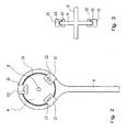
- Fig. 2 a suspension of the pendulum
- Fig. 3 a side view of the suspension according to Fig. 2
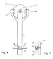
- Fig. 4 a suspension of the pendulum
- Fig. 5 a side view of a compound of the drive cylinder with the pendulum rod
- Fig. 6 a side view of the device according to another example, which is not part of the invention
- the FIGS. 7 and 8 a schematic view of an embodiment of the invention
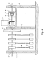
- Fig. 9 a schematic side view of a second embodiment
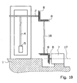
- Fig. 10 a schematic front view of the second embodiment.
- Fig. 1 illustrated device has at least one rigid pendulum, which on a continuous shaft. 2 is stored.
- the pendulum axis is, as directly from the Fig. 1 . 2 . 4 and 6 shows in the axis of rotation of the shaft 2.
- the power transmission from the shaft 2 to a in Fig. 1 not shown generator for generating electrical energy via a wave washer 9, which is rigidly connected to the shaft 2.
- the pendulum is equipped with gripping jaws 12, via which the power transmission from the pendulum to the wave washer 9 is controlled.
- the jaws 12 are arranged in a shaft plate 9 encompassing the jaw saddle 11.
- the pendulum By a drive cylinder 13 which is reciprocable in the direction of arrow B, the pendulum is placed in a pendelafter oscillatory motion along the vibration path A.
- the drive cylinder is connected via a push rod 14 with the pendulum rod 4 and with a building 1.
- the shaft 2 In the building, the shaft 2 is rotatably mounted (not in Fig. 1 shown). Since due to the deflection of the pendulum, the spatial distances and angles between the point of application of the push rod 14 to the pendulum rod 4 and the push rod 14 with the structure 1 are variable, the push rod 14 is hinged to the pendulum rod 4 and has a similar articulation in the form of a push rod fixation 15 on the building 1 on.
- the pendulum oscillates and absorbs kinetic energy as well as potential energy in the gravitational field of the earth.
- the potential energy is converted into kinetic energy as the pendulum swings back from a deflected position to a home position. If, in this phase, the gripping jaws 12 act on the wave washer 9,
- the shaft 2 is also set in motion by the pendulum motion.
- the gripping jaws 12 allow a certain slip when the pendulum oscillates too slowly or in the opposite direction to the desired direction of rotation of the shaft 2.
- the drive cylinder 13 for driving the pendulum may be a hydraulic cylinder, a pneumatic cylinder, etc.
- any form of energy can be used here, for example the potential energy of natural or artificial water vapor, shock, human or animal thrust and the like.
- the energy can be present in pulse-like form or in the form of elongated pulses or previously brought into such a form. If electrical energy is pulse-like, it can first be converted by the device into kinetic energy (pendulum momentum) and then into constant electrical energy.
- the drive form of the cylinders together with the energy storage in oscillating pendulums leads to a conversion of short strong energy pulses into a constant electric energy of somewhat smaller size.
- Fig. 2 forms the end of the pendulum rod 4 connected to the shaft 2 a ring which engages with a hinge 10, for example in the form of a ball bearing, the wave washer 9 of the shaft 2.
- the ring has back saddles 11, the gripping jaws are pressed against the wave washer 9.
- Fig. 3 a sectional side view of the device according to Fig. 2 , It is shown that the wave washer 9 is rigidly connected to the shaft 2.
- Fig. 4 is the corresponding end of the pendulum rod 4 U-shaped or fork-shaped and surrounds the wave washer 9.
- the pendulum rod 4 is rotatably connected directly to the shaft in this solution.
- the push rod fixing 15 is arranged on the pendulum rod 4.
- the push rod fixing 15 differs from a joint by gripping jaws 12 provided here as well.
- the pendulum in the basic position or in a deflected position can be fixed (such as breaks in operation), without the drive cylinder 13 this must be permanently applied with a pressure value.
- Fig. 6 the device is shown with exemplary four parallel suspended on a shaft 2 commuting.
- the shaft 2 is connected in shaft bearings 3 with the structure 1.
- Each pendulum is connected to a separate drive cylinder, not shown here.
- energy-generating generators 7 are driven, for example via bevel gears 8.
- By four phase-shifted oscillating pendulum ensures that the flywheel can operate in continuous operation.
- a massive flywheel 6 can promote a smooth running of the shaft 2, as it dampens or buffers the temporary energy inputs of individual pendulum.
- the pendulum rod 4 is suspended in a frame 16 and in turn drives a lying in the axis of the pendulum shaft 2 at.
- the frame 16 is seated on a tilting axis 17 on the floor 1 of a building, a frame construction, a table or the like.
- the tilting axis 17 can be embodied as a joint or, in a simpler form, as a wedge mounted on a plane.
- the geometry of the frame 16 allows it to tilt about the tilting axis 17 Fig.
- the frame 16 may also be caused to tilt by other types of periodic or near-periodic forms of energy. Provided is only that the tilting force is entered over a distance away from the tilting axis 17 in the frame 16 to form a lever arm.
- the advantage here is that not a heavy pendulum weight 5, but in comparison to a lower mass frame 16 must be deflected at the beginning of the pendulum motion. The pendulum weight 5 is then caused to move by gravity and can immediately drive a generator (not shown).
- the pendulum rod 4 is connected to the shaft 2 via a conventional ratchet system.
- the ratchet system causes the pendulum to swing freely in one direction and rigidly connects it to the shaft 2 in the other direction to transmit the rotational energy of the pendulum to the shaft 2 and the connected generator 7.
- Fig. 9 the drive cylinder is articulated above the shaft 2 to the frame 16. Even small deflections of the frame 16 can lead to a rocking of the pendulum with suitable periodic control of the drive cylinder 13, from which subsequently more energy is removed.
- the frame 16 is in Fig. 9 shown from the side and in Fig. 10 from the beginning.
- the rotational energy of the pendulum on the shaft 2 by means of further waves and bevel gears 8 can be passed to a generator 7.
- the pendulum system including frame 16 is continuous commutes around the tilting axis 17 around.
- One way to extract the rotational energy through waves shows Fig.
- a shaft 18 carried along with the oscillating frame 16 moves a generator 7 whose axis lies in the tilting axis 17 of the frame 16.
- the generator 7 can be fixed and get rotational energy of the pendulum via the mitschwankende with the frame 16 shaft 2 get.
Landscapes
- Engineering & Computer Science (AREA)
- Chemical & Material Sciences (AREA)
- Combustion & Propulsion (AREA)
- Mechanical Engineering (AREA)
- General Engineering & Computer Science (AREA)
- Connection Of Motors, Electrical Generators, Mechanical Devices, And The Like (AREA)
- Other Liquid Machine Or Engine Such As Wave Power Use (AREA)
Claims (4)
- Dispositif de conversion d'une énergie cinétique en une énergie électrique, équipé d'un pendule comprenant une tige de pendule (4) et un poids de pendule (5), lequel pendule est suspendu de manière oscillante sur un arbre (2), dans lequel le pendule est suspendu dans un cadre (16) basculant, dont l'axe de basculement (17) se trouve en dessous d'une trajectoire d'oscillation (A) du pendule et est parallèle à l'axe du pendule, et dans lequel une tige de poussée (14) d'un cylindre de commande (13) hydraulique ou pneumatique alimenté en énergie est reliée au cadre (16) pour l'entraînement du pendule et où le cylindre de commande (13) est articulé au niveau des éléments du dispositif qui convertissent en énergie électrique, caractérisé en ce que le dispositif présente un générateur (7) relié à l'arbre (2), lequel permet de convertir l'énergie de rotation du pendule en une énergie électrique, un moyen étant en outre prévu, grâce auquel le pendule est relié de manière fixe à l'arbre (2) lorsqu'il oscille dans une direction prédéterminée.
- Dispositif selon la revendication 1, caractérisé en ce que le cylindre de commande (13) peut être actionné de manière périodique par l'intermédiaire d'un système de réglage associé.
- Dispositif selon la revendication 1 ou 2, caractérisé en ce que le dispositif présente un volant (6), qui peut être entraîné par l'arbre (2) afin d'obtenir une vitesse de rotation de l'arbre (2) en constante augmentation.
- Dispositif selon l'une quelconque des revendications 1 à 3, caractérisé en ce que le dispositif présente deux pendules ou plus, qui sont disposés de manière parallèle sur l'arbre (2).
Applications Claiming Priority (2)
| Application Number | Priority Date | Filing Date | Title |
|---|---|---|---|
| ATA924/2010A AT509918B1 (de) | 2010-06-07 | 2010-06-07 | Vorrichtung zur umwandlung von kinetischer energie in elektrische energie |
| PCT/AT2011/000245 WO2011153563A2 (fr) | 2010-06-07 | 2011-05-30 | Dispositif de transformation d'énergie cinétique en énergie électrique |
Publications (2)
| Publication Number | Publication Date |
|---|---|
| EP2577060A2 EP2577060A2 (fr) | 2013-04-10 |
| EP2577060B1 true EP2577060B1 (fr) | 2015-03-04 |
Family
ID=44627532
Family Applications (1)
| Application Number | Title | Priority Date | Filing Date |
|---|---|---|---|
| EP11727906.7A Active EP2577060B1 (fr) | 2010-06-07 | 2011-05-30 | Dispositif de transformation d'énergie cinétique en énergie électrique |
Country Status (6)
| Country | Link |
|---|---|
| US (1) | US9112434B2 (fr) |
| EP (1) | EP2577060B1 (fr) |
| JP (1) | JP5726298B2 (fr) |
| AT (1) | AT509918B1 (fr) |
| CA (1) | CA2801940A1 (fr) |
| WO (1) | WO2011153563A2 (fr) |
Families Citing this family (18)
| Publication number | Priority date | Publication date | Assignee | Title |
|---|---|---|---|---|
| US8816516B2 (en) * | 2011-02-10 | 2014-08-26 | Anh VUONG | Apparatus for generating energy using mechanical energy and gravitational energy |
| US9347332B2 (en) * | 2011-07-28 | 2016-05-24 | Mitsui Engineering & Shipbuilding | Dynamo with columnar oscillator |
| US20140183874A1 (en) * | 2012-09-23 | 2014-07-03 | Pedro Enrique Valderrama | Pumped Swing Based Spinning System |
| WO2014108169A1 (fr) * | 2013-01-08 | 2014-07-17 | Aktiebolaget Skf | Bouchon d'extrémité pour ensemble palier |
| CN203430718U (zh) | 2013-07-30 | 2014-02-12 | 比亚迪股份有限公司 | 发电装置 |
| GB2518633B (en) * | 2013-09-26 | 2015-10-28 | Martin John Wickett | Energy production device and system |
| GB2524284B (en) * | 2014-03-19 | 2020-04-22 | Fothergill Alexander | Assisted pendulum device |
| US20170022981A1 (en) * | 2015-04-24 | 2017-01-26 | Siu Hong Sun | Pendulum-type lever power generation device and method thereof |
| WO2017115021A1 (fr) * | 2015-12-30 | 2017-07-06 | Maurice Granger | Mecanisme equilibre pour economie d'energie, machine tournante et procede de mise en oeuvre |
| WO2018069584A1 (fr) * | 2017-03-28 | 2018-04-19 | Maurice Granger | Mecanisme oscillatoire a centrifugations croisées simultanées, machine et procédé de mise en oeuvre |
| DK179738B1 (en) * | 2017-10-11 | 2019-04-30 | Ravn Niels | Wind-Driven Energy Converting Device |
| DE102017126245A1 (de) * | 2017-11-09 | 2019-05-09 | Murat Rona | Vorrichtung zur Erzeugung von elektrischer Energie |
| CN115413393A (zh) * | 2020-03-27 | 2022-11-29 | 松下知识产权经营株式会社 | 电力机械装置 |
| CN111498043B (zh) * | 2020-04-26 | 2021-05-11 | 中船黄埔文冲船舶有限公司 | 一种船舶倾斜试验装置 |
| AU2023233108C1 (en) * | 2023-02-13 | 2025-11-20 | Agresta, Ferdinando MR | Duty cycle reducer system |
| CN118705107A (zh) * | 2024-07-22 | 2024-09-27 | 日生创新(厦门)建筑设计有限公司 | 波浪发电舱 |
| GB2702341A (en) * | 2024-10-31 | 2026-06-10 | Yan Sun Ho | Pendulum generator |
| WO2026129385A1 (fr) * | 2024-12-18 | 2026-06-25 | 石家庄健牧饲料有限公司 | Dispositif de production d'énergie rotative |
Family Cites Families (15)
| Publication number | Priority date | Publication date | Assignee | Title |
|---|---|---|---|---|
| GB109123A (en) * | 1916-09-20 | 1917-09-06 | Frederick Natusch Maude | Improvements in or relating to the Utilisation of Centrifugal Forces Developed from a Weight Rotated or Oscillated about an Axis. |
| JPS5185407A (ja) * | 1975-01-23 | 1976-07-27 | Eisuke Funakoshi | Jidohatsudensochi |
| SU735822A1 (ru) * | 1977-10-25 | 1980-05-25 | Всесоюзный заочный машиностроительный институт | Устройство преобразовани энергии колебаний |
| US4452045A (en) * | 1981-04-23 | 1984-06-05 | Trisolar Corp. | Smoothing electrical energy output with mechanical accumulator |
| US4852350A (en) * | 1988-01-25 | 1989-08-01 | Peter Krisko | Energy generator |
| GB2234637B (en) * | 1989-08-05 | 1994-03-16 | Roy Smith | Gravity operated electrical generator |
| US20070137943A1 (en) * | 2003-09-05 | 2007-06-21 | Paul Duclos | Pendulum actuated gearing mechanism and power generation system using same |
| US20050248159A1 (en) * | 2004-05-10 | 2005-11-10 | Seoane Diego Luis Felipe Berna | System and method for converting potential energy into electrical energy |
| RO122313B1 (ro) * | 2004-11-29 | 2009-03-30 | Pavel Nate | Instalaţie de transformare a mişcării de du-te-vino în mişcare de rotaţie |
| US7151322B2 (en) * | 2005-01-25 | 2006-12-19 | Ashraf Makrm Dawoud Eskandr | Transportation and power generating system of gravity and leaf springs |
| AT504707A1 (de) | 2006-12-22 | 2008-07-15 | Eichhorn Karl | Schwungkraftmaschine |
| WO2009004645A2 (fr) * | 2007-05-12 | 2009-01-08 | Bharat Shastri | Puissance générée par une balançoire - une nouvelle technique de production d'électricité |
| JP2009264362A (ja) * | 2008-04-25 | 2009-11-12 | Hideo Tanaka | フーコーの振り子発電設備 |
| JP3145638U (ja) * | 2008-08-01 | 2008-10-16 | 善光 中川 | 振子発電装置 |
| US8026620B2 (en) * | 2008-11-14 | 2011-09-27 | Hobdy Miles | Wave energy converter |
-
2010
- 2010-06-07 AT ATA924/2010A patent/AT509918B1/de active
-
2011
- 2011-05-30 US US13/702,935 patent/US9112434B2/en not_active Expired - Fee Related
- 2011-05-30 CA CA2801940A patent/CA2801940A1/fr not_active Abandoned
- 2011-05-30 JP JP2013513495A patent/JP5726298B2/ja not_active Expired - Fee Related
- 2011-05-30 EP EP11727906.7A patent/EP2577060B1/fr active Active
- 2011-05-30 WO PCT/AT2011/000245 patent/WO2011153563A2/fr not_active Ceased
Also Published As
| Publication number | Publication date |
|---|---|
| US9112434B2 (en) | 2015-08-18 |
| JP2013529276A (ja) | 2013-07-18 |
| WO2011153563A3 (fr) | 2012-11-15 |
| EP2577060A2 (fr) | 2013-04-10 |
| US20130207403A1 (en) | 2013-08-15 |
| CA2801940A1 (fr) | 2011-12-15 |
| WO2011153563A2 (fr) | 2011-12-15 |
| AT509918B1 (de) | 2013-09-15 |
| AT509918A1 (de) | 2011-12-15 |
| JP5726298B2 (ja) | 2015-05-27 |
Similar Documents
| Publication | Publication Date | Title |
|---|---|---|
| AT509918B1 (de) | Vorrichtung zur umwandlung von kinetischer energie in elektrische energie | |
| EP3377699B1 (fr) | Groupe de bourrage et procédé de bourrage d'une voie ferrée | |
| DE2934004A1 (de) | Meereswellen-stromerzeugungsanlage | |
| DE2919653A1 (de) | Vorrichtung zur energiegewinnung | |
| DE102009022068A1 (de) | Anordnung zur mittelbaren Umwandlung von Meereswellenenergie in elektrische Energie | |
| DE102016118010A1 (de) | Schwingungserreger zur Belastungsprüfung eines Rotorblatts, System, Prüfstand und Anordnung mit einem solchen Schwingungserreger sowie Betriebsverfahren | |
| AT519219A4 (de) | Stopfaggregat zum Unterstopfen von Schwellen eines Gleises | |
| DE102011116751A1 (de) | Aktive Knieprothese mit Kegelstirnradgetriebe | |
| DE102013112455A1 (de) | Oszillierend antreibbare Werkzeugmaschine | |
| DE2812811A1 (de) | Neuartige kraft- und arbeitsmaschine hohe wirkungsgrades mit antrieb durch ein schwingendes pendel relativ grosser masse und ausnutzung der bewegungsenergie des pendels fuer den antrieb einer arbeitswelle | |
| EP4571097B1 (fr) | Production d'énergie électrique par énergie éolienne | |
| DE102011054112A1 (de) | Vorrichtung zur Prüfung von Windenergieanlagen | |
| DE102007035760B4 (de) | Schlagflügelanordnung | |
| DE19710601C2 (de) | Bewegungsgenerator | |
| EP3115605B1 (fr) | Dispositif et procede de preparation d'air comprime | |
| DE102017004445A1 (de) | Verfahren und Vorrichtung zur dynamischen Kraftverstärkung | |
| DE2031673C3 (de) | Federhammer | |
| DE102014015432B4 (de) | Vorrichtung zur Umwandlung von extrinsischen Schwingungsbewegungen in elektrische Energie | |
| DE202013011687U1 (de) | Oszillierend antreibbare Werkzeugmaschine | |
| DE102013011765B4 (de) | An- und Abtrieb der Inversionsbewegung von n-gliedrigen Gelenkketten | |
| WO2008077164A1 (fr) | Machine à force centrifuge | |
| DE324970C (de) | Verfahren zum Daempfen schwingender Bewegungen von Koerpern, insbesondere der Rollbewegungen von Schiffen | |
| DE202017002470U1 (de) | Vorrichtung zur dynamischen Kraftverstärkung | |
| DE235979C (fr) | ||
| EP2140946B1 (fr) | Dispositif de production de vibrations |
Legal Events
| Date | Code | Title | Description |
|---|---|---|---|
| PUAI | Public reference made under article 153(3) epc to a published international application that has entered the european phase |
Free format text: ORIGINAL CODE: 0009012 |
|
| 17P | Request for examination filed |
Effective date: 20121203 |
|
| AK | Designated contracting states |
Kind code of ref document: A2 Designated state(s): AL AT BE BG CH CY CZ DE DK EE ES FI FR GB GR HR HU IE IS IT LI LT LU LV MC MK MT NL NO PL PT RO RS SE SI SK SM TR |
|
| GRAP | Despatch of communication of intention to grant a patent |
Free format text: ORIGINAL CODE: EPIDOSNIGR1 |
|
| DAX | Request for extension of the european patent (deleted) | ||
| INTG | Intention to grant announced |
Effective date: 20130930 |
|
| GRAL | Information related to payment of fee for publishing/printing deleted |
Free format text: ORIGINAL CODE: EPIDOSDIGR3 |
|
| GRAS | Grant fee paid |
Free format text: ORIGINAL CODE: EPIDOSNIGR3 |
|
| GRAS | Grant fee paid |
Free format text: ORIGINAL CODE: EPIDOSNIGR3 |
|
| GRAA | (expected) grant |
Free format text: ORIGINAL CODE: 0009210 |
|
| AK | Designated contracting states |
Kind code of ref document: B1 Designated state(s): AL AT BE BG CH CY CZ DE DK EE ES FI FR GB GR HR HU IE IS IT LI LT LU LV MC MK MT NL NO PL PT RO RS SE SI SK SM TR |
|
| REG | Reference to a national code |
Ref country code: GB Ref legal event code: FG4D Free format text: NOT ENGLISH |
|
| REG | Reference to a national code |
Ref country code: CH Ref legal event code: EP |
|
| REG | Reference to a national code |
Ref country code: IE Ref legal event code: FG4D Free format text: LANGUAGE OF EP DOCUMENT: GERMAN |
|
| REG | Reference to a national code |
Ref country code: AT Ref legal event code: REF Ref document number: 714134 Country of ref document: AT Kind code of ref document: T Effective date: 20150415 |
|
| REG | Reference to a national code |
Ref country code: DE Ref legal event code: R096 Ref document number: 502011006132 Country of ref document: DE Effective date: 20150416 |
|
| REG | Reference to a national code |
Ref country code: NL Ref legal event code: VDEP Effective date: 20150304 |
|
| PG25 | Lapsed in a contracting state [announced via postgrant information from national office to epo] |
Ref country code: FI Free format text: LAPSE BECAUSE OF FAILURE TO SUBMIT A TRANSLATION OF THE DESCRIPTION OR TO PAY THE FEE WITHIN THE PRESCRIBED TIME-LIMIT Effective date: 20150304 Ref country code: LT Free format text: LAPSE BECAUSE OF FAILURE TO SUBMIT A TRANSLATION OF THE DESCRIPTION OR TO PAY THE FEE WITHIN THE PRESCRIBED TIME-LIMIT Effective date: 20150304 Ref country code: ES Free format text: LAPSE BECAUSE OF FAILURE TO SUBMIT A TRANSLATION OF THE DESCRIPTION OR TO PAY THE FEE WITHIN THE PRESCRIBED TIME-LIMIT Effective date: 20150304 Ref country code: SE Free format text: LAPSE BECAUSE OF FAILURE TO SUBMIT A TRANSLATION OF THE DESCRIPTION OR TO PAY THE FEE WITHIN THE PRESCRIBED TIME-LIMIT Effective date: 20150304 Ref country code: HR Free format text: LAPSE BECAUSE OF FAILURE TO SUBMIT A TRANSLATION OF THE DESCRIPTION OR TO PAY THE FEE WITHIN THE PRESCRIBED TIME-LIMIT Effective date: 20150304 Ref country code: NO Free format text: LAPSE BECAUSE OF FAILURE TO SUBMIT A TRANSLATION OF THE DESCRIPTION OR TO PAY THE FEE WITHIN THE PRESCRIBED TIME-LIMIT Effective date: 20150604 |
|
| REG | Reference to a national code |
Ref country code: LT Ref legal event code: MG4D |
|
| PG25 | Lapsed in a contracting state [announced via postgrant information from national office to epo] |
Ref country code: GR Free format text: LAPSE BECAUSE OF FAILURE TO SUBMIT A TRANSLATION OF THE DESCRIPTION OR TO PAY THE FEE WITHIN THE PRESCRIBED TIME-LIMIT Effective date: 20150605 Ref country code: RS Free format text: LAPSE BECAUSE OF FAILURE TO SUBMIT A TRANSLATION OF THE DESCRIPTION OR TO PAY THE FEE WITHIN THE PRESCRIBED TIME-LIMIT Effective date: 20150304 Ref country code: LV Free format text: LAPSE BECAUSE OF FAILURE TO SUBMIT A TRANSLATION OF THE DESCRIPTION OR TO PAY THE FEE WITHIN THE PRESCRIBED TIME-LIMIT Effective date: 20150304 |
|
| PG25 | Lapsed in a contracting state [announced via postgrant information from national office to epo] |
Ref country code: NL Free format text: LAPSE BECAUSE OF FAILURE TO SUBMIT A TRANSLATION OF THE DESCRIPTION OR TO PAY THE FEE WITHIN THE PRESCRIBED TIME-LIMIT Effective date: 20150304 |
|
| REG | Reference to a national code |
Ref country code: FR Ref legal event code: PLFP Year of fee payment: 5 |
|
| PG25 | Lapsed in a contracting state [announced via postgrant information from national office to epo] |
Ref country code: RO Free format text: LAPSE BECAUSE OF FAILURE TO SUBMIT A TRANSLATION OF THE DESCRIPTION OR TO PAY THE FEE WITHIN THE PRESCRIBED TIME-LIMIT Effective date: 20150304 Ref country code: SK Free format text: LAPSE BECAUSE OF FAILURE TO SUBMIT A TRANSLATION OF THE DESCRIPTION OR TO PAY THE FEE WITHIN THE PRESCRIBED TIME-LIMIT Effective date: 20150304 Ref country code: PT Free format text: LAPSE BECAUSE OF FAILURE TO SUBMIT A TRANSLATION OF THE DESCRIPTION OR TO PAY THE FEE WITHIN THE PRESCRIBED TIME-LIMIT Effective date: 20150706 Ref country code: CZ Free format text: LAPSE BECAUSE OF FAILURE TO SUBMIT A TRANSLATION OF THE DESCRIPTION OR TO PAY THE FEE WITHIN THE PRESCRIBED TIME-LIMIT Effective date: 20150304 Ref country code: EE Free format text: LAPSE BECAUSE OF FAILURE TO SUBMIT A TRANSLATION OF THE DESCRIPTION OR TO PAY THE FEE WITHIN THE PRESCRIBED TIME-LIMIT Effective date: 20150304 |
|
| REG | Reference to a national code |
Ref country code: CH Ref legal event code: NV Representative=s name: ISLER AND PEDRAZZINI AG, CH |
|
| PG25 | Lapsed in a contracting state [announced via postgrant information from national office to epo] |
Ref country code: IS Free format text: LAPSE BECAUSE OF FAILURE TO SUBMIT A TRANSLATION OF THE DESCRIPTION OR TO PAY THE FEE WITHIN THE PRESCRIBED TIME-LIMIT Effective date: 20150704 Ref country code: PL Free format text: LAPSE BECAUSE OF FAILURE TO SUBMIT A TRANSLATION OF THE DESCRIPTION OR TO PAY THE FEE WITHIN THE PRESCRIBED TIME-LIMIT Effective date: 20150304 |
|
| REG | Reference to a national code |
Ref country code: DE Ref legal event code: R097 Ref document number: 502011006132 Country of ref document: DE |
|
| PG25 | Lapsed in a contracting state [announced via postgrant information from national office to epo] |
Ref country code: IT Free format text: LAPSE BECAUSE OF FAILURE TO SUBMIT A TRANSLATION OF THE DESCRIPTION OR TO PAY THE FEE WITHIN THE PRESCRIBED TIME-LIMIT Effective date: 20150304 |
|
| PLBE | No opposition filed within time limit |
Free format text: ORIGINAL CODE: 0009261 |
|
| STAA | Information on the status of an ep patent application or granted ep patent |
Free format text: STATUS: NO OPPOSITION FILED WITHIN TIME LIMIT |
|
| PG25 | Lapsed in a contracting state [announced via postgrant information from national office to epo] |
Ref country code: MC Free format text: LAPSE BECAUSE OF FAILURE TO SUBMIT A TRANSLATION OF THE DESCRIPTION OR TO PAY THE FEE WITHIN THE PRESCRIBED TIME-LIMIT Effective date: 20150304 Ref country code: DK Free format text: LAPSE BECAUSE OF FAILURE TO SUBMIT A TRANSLATION OF THE DESCRIPTION OR TO PAY THE FEE WITHIN THE PRESCRIBED TIME-LIMIT Effective date: 20150304 |
|
| 26N | No opposition filed |
Effective date: 20151207 |
|
| PG25 | Lapsed in a contracting state [announced via postgrant information from national office to epo] |
Ref country code: SI Free format text: LAPSE BECAUSE OF FAILURE TO SUBMIT A TRANSLATION OF THE DESCRIPTION OR TO PAY THE FEE WITHIN THE PRESCRIBED TIME-LIMIT Effective date: 20150304 |
|
| REG | Reference to a national code |
Ref country code: FR Ref legal event code: PLFP Year of fee payment: 6 |
|
| PG25 | Lapsed in a contracting state [announced via postgrant information from national office to epo] |
Ref country code: MT Free format text: LAPSE BECAUSE OF FAILURE TO SUBMIT A TRANSLATION OF THE DESCRIPTION OR TO PAY THE FEE WITHIN THE PRESCRIBED TIME-LIMIT Effective date: 20150304 |
|
| REG | Reference to a national code |
Ref country code: FR Ref legal event code: PLFP Year of fee payment: 7 |
|
| PG25 | Lapsed in a contracting state [announced via postgrant information from national office to epo] |
Ref country code: HU Free format text: LAPSE BECAUSE OF FAILURE TO SUBMIT A TRANSLATION OF THE DESCRIPTION OR TO PAY THE FEE WITHIN THE PRESCRIBED TIME-LIMIT; INVALID AB INITIO Effective date: 20110530 Ref country code: BG Free format text: LAPSE BECAUSE OF FAILURE TO SUBMIT A TRANSLATION OF THE DESCRIPTION OR TO PAY THE FEE WITHIN THE PRESCRIBED TIME-LIMIT Effective date: 20150304 Ref country code: SM Free format text: LAPSE BECAUSE OF FAILURE TO SUBMIT A TRANSLATION OF THE DESCRIPTION OR TO PAY THE FEE WITHIN THE PRESCRIBED TIME-LIMIT Effective date: 20150304 |
|
| PG25 | Lapsed in a contracting state [announced via postgrant information from national office to epo] |
Ref country code: CY Free format text: LAPSE BECAUSE OF FAILURE TO SUBMIT A TRANSLATION OF THE DESCRIPTION OR TO PAY THE FEE WITHIN THE PRESCRIBED TIME-LIMIT Effective date: 20150304 |
|
| REG | Reference to a national code |
Ref country code: AT Ref legal event code: MM01 Ref document number: 714134 Country of ref document: AT Kind code of ref document: T Effective date: 20160530 |
|
| PG25 | Lapsed in a contracting state [announced via postgrant information from national office to epo] |
Ref country code: BE Free format text: LAPSE BECAUSE OF NON-PAYMENT OF DUE FEES Effective date: 20150531 |
|
| PG25 | Lapsed in a contracting state [announced via postgrant information from national office to epo] |
Ref country code: AT Free format text: LAPSE BECAUSE OF NON-PAYMENT OF DUE FEES Effective date: 20160530 Ref country code: TR Free format text: LAPSE BECAUSE OF FAILURE TO SUBMIT A TRANSLATION OF THE DESCRIPTION OR TO PAY THE FEE WITHIN THE PRESCRIBED TIME-LIMIT Effective date: 20150304 |
|
| REG | Reference to a national code |
Ref country code: FR Ref legal event code: PLFP Year of fee payment: 8 |
|
| PG25 | Lapsed in a contracting state [announced via postgrant information from national office to epo] |
Ref country code: MK Free format text: LAPSE BECAUSE OF FAILURE TO SUBMIT A TRANSLATION OF THE DESCRIPTION OR TO PAY THE FEE WITHIN THE PRESCRIBED TIME-LIMIT Effective date: 20150304 |
|
| PGFP | Annual fee paid to national office [announced via postgrant information from national office to epo] |
Ref country code: LU Payment date: 20180530 Year of fee payment: 8 |
|
| PGFP | Annual fee paid to national office [announced via postgrant information from national office to epo] |
Ref country code: IE Payment date: 20180524 Year of fee payment: 8 Ref country code: CH Payment date: 20180530 Year of fee payment: 8 |
|
| PGFP | Annual fee paid to national office [announced via postgrant information from national office to epo] |
Ref country code: FR Payment date: 20180529 Year of fee payment: 8 |
|
| PG25 | Lapsed in a contracting state [announced via postgrant information from national office to epo] |
Ref country code: AL Free format text: LAPSE BECAUSE OF FAILURE TO SUBMIT A TRANSLATION OF THE DESCRIPTION OR TO PAY THE FEE WITHIN THE PRESCRIBED TIME-LIMIT Effective date: 20150304 |
|
| PGFP | Annual fee paid to national office [announced via postgrant information from national office to epo] |
Ref country code: GB Payment date: 20180517 Year of fee payment: 8 |
|
| REG | Reference to a national code |
Ref country code: DE Ref legal event code: R084 Ref document number: 502011006132 Country of ref document: DE |
|
| REG | Reference to a national code |
Ref country code: CH Ref legal event code: PL |
|
| GBPC | Gb: european patent ceased through non-payment of renewal fee |
Effective date: 20190530 |
|
| PG25 | Lapsed in a contracting state [announced via postgrant information from national office to epo] |
Ref country code: CH Free format text: LAPSE BECAUSE OF NON-PAYMENT OF DUE FEES Effective date: 20190531 Ref country code: LI Free format text: LAPSE BECAUSE OF NON-PAYMENT OF DUE FEES Effective date: 20190531 |
|
| PG25 | Lapsed in a contracting state [announced via postgrant information from national office to epo] |
Ref country code: LU Free format text: LAPSE BECAUSE OF NON-PAYMENT OF DUE FEES Effective date: 20190530 |
|
| PG25 | Lapsed in a contracting state [announced via postgrant information from national office to epo] |
Ref country code: IE Free format text: LAPSE BECAUSE OF NON-PAYMENT OF DUE FEES Effective date: 20190530 Ref country code: GB Free format text: LAPSE BECAUSE OF NON-PAYMENT OF DUE FEES Effective date: 20190530 |
|
| PG25 | Lapsed in a contracting state [announced via postgrant information from national office to epo] |
Ref country code: FR Free format text: LAPSE BECAUSE OF NON-PAYMENT OF DUE FEES Effective date: 20190531 |
|
| PGFP | Annual fee paid to national office [announced via postgrant information from national office to epo] |
Ref country code: DE Payment date: 20260415 Year of fee payment: 16 |