EP2577074B1 - Vis autotaraudeuse - Google Patents
Vis autotaraudeuse Download PDFInfo
- Publication number
- EP2577074B1 EP2577074B1 EP11722086.3A EP11722086A EP2577074B1 EP 2577074 B1 EP2577074 B1 EP 2577074B1 EP 11722086 A EP11722086 A EP 11722086A EP 2577074 B1 EP2577074 B1 EP 2577074B1
- Authority
- EP
- European Patent Office
- Prior art keywords
- screw
- self
- longitudinal axis
- tip
- boring
- Prior art date
- Legal status (The legal status is an assumption and is not a legal conclusion. Google has not performed a legal analysis and makes no representation as to the accuracy of the status listed.)
- Active
Links
Images


Classifications
-
- F—MECHANICAL ENGINEERING; LIGHTING; HEATING; WEAPONS; BLASTING
- F16—ENGINEERING ELEMENTS AND UNITS; GENERAL MEASURES FOR PRODUCING AND MAINTAINING EFFECTIVE FUNCTIONING OF MACHINES OR INSTALLATIONS; THERMAL INSULATION IN GENERAL
- F16B—DEVICES FOR FASTENING OR SECURING CONSTRUCTIONAL ELEMENTS OR MACHINE PARTS TOGETHER, e.g. NAILS, BOLTS, CIRCLIPS, CLAMPS, CLIPS OR WEDGES; JOINTS OR JOINTING
- F16B25/00—Screws that cut thread in the body into which they are screwed, e.g. wood screws
- F16B25/10—Screws performing an additional function to thread-forming, e.g. drill screws or self-piercing screws
- F16B25/103—Screws performing an additional function to thread-forming, e.g. drill screws or self-piercing screws by means of a drilling screw-point, i.e. with a cutting and material removing action
Definitions
- the invention relates to a self - drilling screw having a bore portion and a threaded and core diameter shank, said bore portion having a peripheral surface and a drill bit eccentrically disposed with respect to a longitudinal axis of said screw and having at least one first cutting edge disposed with respect to the longitudinal axis of said drill bit Bolt obliquely, and wherein the drill bit is located on an imaginary circle about the longitudinal axis of the screw whose diameter is equal to or substantially equal to the core diameter.
- a similar self-drilling screw is from the document EP 1 430 227 B1 known.
- This known screw is neither intended nor suitable for use with wood. It is used to attach a plate-shaped object on a substructure, the substructure is usually made of metal, often made of profile parts made of thin sheet metal.
- the plate-shaped article is usually a cladding panel made of ceramic, fiber cement, stone or the like. Brittle material for producing a building cladding. Due to solar radiation, the building cladding moves on the substructure. Therefore, through holes are used in the cladding plates, which receive the mounting screws with sufficient clearance.
- self-drilling screws are used, which are provided with freely projecting transversely to the screw axis wings, which widen the through hole as desired.
- the screw according to the aforesaid document is specially adapted to produce a through-hole receiving the shank of the screw without the aid of such wings, only in the plate-shaped article and not in the thinner metallic substructure.
- its boring part has an off-center drill bit with respect to the longitudinal axis of the screw and an oblique cutting edge extending from the drill bit over the entire width of the boring part.
- the drill bit forms from the beginning of the drilling process a centering tip for the screw, which is why the screw is arranged obliquely from the beginning of the drilling process.
- the hole made in the plate-shaped article is not cylindrical because of the circular motion of the drilling part but is conically widened and increases in diameter toward the substructure. When the drill bit finally reaches the bottom of the substructure, the hole has been widened to its maximum size.
- Another self-drilling screw which also has an off-center drill bit, is from the document US 4,568,229 A known. On either side of the drill bit, the screw has two cutting edges that are substantially on a diameter and intersect a hole that is substantially smaller in diameter than the core diameter of the thread.
- This known screw is not intended for use in wood, but for screwing into a substructure made of sheet steel.
- This document is therefore concerned with the task of creating a self-tapping screw, which avoids these disadvantages and, above all, almost excludes a running of the screw when screwing and creates a screw with high tear resistance.
- This self-tapping screw has a tip that has no radius and is arranged offset slightly laterally relative to the axis of the shaft.
- This self-tapping screw should therefore have the advantage that by the displacement of the tip relative to the axis of the screw shaft when screwing the screw in sheet metal a sheet passage (collar formation) is obtained, so that the thread not only in the sheet, but also in this sheet metal passage cuts, whereby the engagement surface for the screw and thus also the pull-out strength are substantially increased.
- a wood screw which is very similar to the self-tapping screw according to the preamble of claim 1, is from the document CH 50995 known.
- the wood screw is designed to be placed without pre-drilling a hole.
- the wood screw creates the hole itself when screwed into wood.
- the tip of the screw is designed as a scraping or milling tool whose largest dimension perpendicular to the screw axis measured equal to the screw shank diameter, which tip when screwing the screw in Wood so finely shavings that they are ground by the screw threads and can spread in the form of wood flour around the thread and the screw shaft, thereby contributing to increasing the liability of the screw in the wood.
- the wood screw has a scraper tip in one embodiment with only one obliquely set sharpness.
- the sharpness does not act boring, that is, does not produce large chips, but the wood is scraped to form fine chips in the rotation of the screw.
- the scraper tip can only have a horizontal sharpness or only an obliquely set sharpness or be provided with several sharpening, which in this case form a so-called scraper or cutter tip. Since a doctor blade with several sharpenings can penetrate more quickly to form fine chips than a doctor blade with only one sharpness, the thread of the screw can have a greater pitch than that of the screws with only one bevel.
- the object of the invention is to provide a self-tapping screw which is screwed into wood with reduced splitting effect and thereby should be easier to produce, with the usual properties of a wood screw such as a high Auszugswert, a low Einformmoment and a good Ansetz should remain guaranteed and wherein the drilled hole should have the core diameter of the thread of the screw.
- the drilling part has a second cutting edge forming a main cutting edge, which is essentially formed by the cut of a rake face and a main rake face and extends from the drill bit substantially parallel or substantially parallel to the longitudinal axis of the screw, that the first cutting edge is a minor cutting edge formed by the cutting of the rake face and a minor relief surface, which extends from the drill bit obliquely to the longitudinal axis of the screw across the width of the drilling part, and that the drilling part is designed as a sickle tip.
- the screw according to the invention drilled by means of a sickle tip a hole whose diameter corresponds to the core diameter of the thread. This ensures the desired high extraction value. Because the sickle tip has an outer major cutting edge that cuts through the wood fibers, the splitting effect is significantly reduced, if not completely eliminated, over the prior art.
- the screw according to the invention requires a low Einformmoment because the sickle tip is placed with the drill bit initially in the center of the hole to be produced on the wood and during the drilling process to form a small hole that increases in diameter quickly, moves out to finally a Make hole with the core diameter of the thread.
- the pressure required to achieve the drilling progress decreases continuously from the beginning of the drilling process until the diameter of the hole has reached the core diameter, which also contributes greatly to reducing the tendency to crack.
- the self-tapping screw according to the invention has the tendency to drill a hole with the core diameter of its thread due to the radially outwardly disposed drill bit, due to the outer major cutting edge and due to the secondary cutting edge extending obliquely across the width of the drill bit from the drill bit.
- the screw according to the invention is placed on the wood with the drill bit in the borehole axis, with increasing depth penetrating into the wood screw, however, the screw longitudinal axis and the borehole axis increasingly approach a position in which they collapse.
- a drilling operation with a self-drilling screw always begins with the application of the drill bit to the surface of the component to be drilled.
- the self-tapping screw according to the invention has a very good Ansetz , ensures a high pull-out force and a low Einformmoment and is inexpensive to produce with low splitting force.
- the drill bit is formed by the cut of the rake face, the minor relief face and the main relief face. Since the main cutting edge and the auxiliary sheath extend from the drill bit, this design means that all cutting edges on the sickle tip of the self-tapping screw according to the invention adjoin one and the same surface, namely the chip surface, which facilitates the production of the cutting edges.
- the secondary cutting edge forms an angle of up to 40 degrees with the longitudinal axis of the screw. This results in a sickle tip with defined Ansetz and a particularly effective effect of major and minor sheath.
- the lateral surface of the drilling part has a diameter which is equal to or substantially equal to the core diameter.
- the drilling part in this case passes into the shank of the screw, so that only a small force is required for screwing the screw into the hole provided with the core diameter.
- the main free surface is a part of the lateral surface of the boring part. In this case, no additional manufacturing steps for the main free surface are required, because the lateral surface, which is preferably cylindrical, is present anyway.
- the sickle tip is substantially parallel to the longitudinal axis of the screw. This can be the most appropriate embodiment for the particular application depending on the type of wood to be drilled.
- the sickle tip at right angles to the rake face occupies half the core diameter. This allows sufficient clearance in the area of the drill bit for discharging the cuttings, in each case with a large length of main and secondary cutting edge.
- the rake face contains the longitudinal axis of the screw.
- the sickle tip can occupy at right angles to the chip surface up to half of the core diameter.
- the rake face forms an angle of up to 30 degrees with the longitudinal axis of the screw.
- the main cutting edge is inclined in a subsequent to the drill bit area by a small angle of up to 10 degrees to the longitudinal axis of the screw against a surface line of the lateral surface.
- This embodiment can be used to further improve the drilling process depending on the type of wood to be drilled.
- the rake face in the longitudinal direction of the screw and then aligned to the drill bit parallel or substantially parallel to the screw longitudinal axis. This can be used to further improve the drilling process over the previous design depending on the type of wood.
- the sickle tip assumes a right angle to the chip surface less than half the core diameter.
- the boring part has, in a region adjoining the drill bit, an outer diameter which is smaller than the core diameter of the shaft by a small distance. Also, this configuration can be used depending on the type of wood to be drilled to improve the drilling process.
- the sickle tip assumes more than half the core diameter at right angles to the rake surface. Although this results in less space for the removal of the cuttings, but allows a greater length of main and Mauscheide.
- the rake face is recessed inwardly from a generating line of the boring part, so that the main cutting edge is parallel or substantially parallel only on a part of its length to the longitudinal axis of the screw.
- the main cutting edge extends obliquely in its immediately adjacent to the drill bit area to the longitudinal axis of the screw and passes at a corner in a region in which they are parallel or substantially parallel to the longitudinal axis the screw extends.
- radii, phases or exemptions are formed at the transition to the shank on the chip surface. This facilitates the removal of the drill cuttings and the manufacture of the sickle tip and prevents the occurrence of stress peaks at the transition between the shaft and the drilling part.
- the thread starts on a part of the shank adjoining the boring part opposite to the drill bit. As a result, the splitting effect is further reduced.
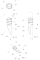
- Fig. 1 consisting of the Figures 1 a-1d shows a first embodiment of a self-tapping screw according to the invention, which in Fig. 1 and is designated in all other figures, each with a total of 10.
- the screw 10 is made of metal.
- the head of the screw 10 is only in Fig. 8 visible and labeled there with 11.
- the screw 10 is provided with a drilling portion 100 which is formed in each of the illustrated embodiments of the invention as a sickle tip.
- the sickle tip is generally designated 101.
- the screw 10 has a shaft 12 provided with a thread 12 and with a core diameter D k .
- Fig. 1 shows in Fig. 1a the self-tapping screw 10 according to the invention in an axial plan view of the drilling member 100 in the direction of an arrow A 'in Fig. 1b , in Fig. 1b the boring part 100 and an adjacent part of the shank 14 of the screw 10 in a side view in the direction of an arrow B 'in Fig. 1c , in Fig. 1c the boring part 100 and the adjacent shaft part in a relation to the representation in Fig. 1b 90 ° rotated view and in Fig. 1d the drilling part 100 and the adjacent shaft part in a perspective view.
- the other embodiments of the self-drilling screw according to the invention are in the Figures 2-7 each shown in the same views.
- the boring part 100 has a lateral surface 22 which, in the exemplary embodiment shown here, is a circular-cylindrical lateral surface.
- the screw 10 has a longitudinal axis 80. Its drill bit 20 is arranged off-center.
- the sickle tip 101 of the drilling part 100 of the screw 10 is provided with a radially outer main cutting edge 30, which is formed by the cut of a rake surface 60 and a main relief surface 90.
- the main cutting edge 30 extends from the drill bit 20 in the embodiment according to Fig. 1 parallel to the longitudinal axis 80.
- the rake surface 60 forms with a side relief surface 70, which in the Figures 1c and 1d is shown, a minor cutting edge 40.
- the secondary cutting edge 40 extends from the drill bit 20 obliquely to the longitudinal axis 80 across the width of the drilling member 100, which in Fig. 1b can be seen.
- the drill bit 20 lies on an imaginary circle about the longitudinal axis 80 of the screw 10. The diameter of this circle is in the embodiment according to Fig. 1 equal to the core diameter D k .
- the drill bit 20 is formed by the cut of the rake surface 60, the minor relief surface 70 and the main relief surface 90, so that the Main cutting edge 30 and the secondary cutting edge 40 adjacent to one and the same surface, namely the clamping surface 60th
- the secondary cutting edge 70 forms as shown in FIG Fig. 1b an angle ⁇ with the longitudinal axis 80 of the screw 10, which may be up to 40 degrees.
- the lateral surface 22 of the boring part 100 has, as shown in FIG Fig. 1c a diameter D a, the according to the embodiment in Fig. 1 is equal to the core diameter D k .
- the main free surface 90 is a part of the lateral surface 22 of the boring part 100 and is thus here a cylindrical surface.
- the sickle tip 101 is substantially parallel to the longitudinal axis 80 of the screw 10 and, as shown in FIG Fig. 1c perpendicular to the rake face 60 the half core diameter D k , wherein in the embodiment according to Fig. 1 the rake surface 60 includes the longitudinal axis 80 of the screw 10.
- the screw 10 according to the invention can be produced by hot or cold working and / or machining of a cylindrical starting material or a screw blank. The manner of manufacture is not important to the understanding of the invention.
- the above-described formation of the screw 10 serves the purpose of a plate-shaped workpiece 120, the in Fig. 8 is indicated to produce a through hole which receives the threaded shaft 12 with the shaft 14 without play and into which the thread 12 of the shaft 14 cuts a counter thread. It should be reduced to a negligible extent by the special design of the sickle tip and by their eccentric arrangement, the splitting effect that usually produces a conventional wood screw when screwed into wood.
- the sickle tip 101 is arranged not only off-center, but also has the parallel to the longitudinal axis 80 of the screw 10 or substantially parallel main cutting edge 30 and obliquely to the longitudinal axis 80 over the width of the boring part 100 extending secondary cutting edge 40th Die Mode of action of the off-center sickle tip 101 and formed on this
- the main and minor cutting edge in setting the self-tapping screw will be explained below with reference to FIG Fig. 8 explained.
- Fig. 2 or Fig. 2a-2d shows a second embodiment of the self-tapping screw 10 according to the invention, in which a sickle tip 102 is inclined against the longitudinal axis 80 of the screw 10, as shown in the Figures 2c and 2d can be seen.
- the rake surface 60 forms an angle ⁇ of up to 30 degrees with the longitudinal axis 80 of the screw.
- the sickle tip 102 at right angles to the longitudinal axis 80 takes up half the core diameter D k .
- the rake face 60 does not contain the longitudinal axis 80 of the screw here.
- Fig. 2b is the main cutting edge 30 inclined in a subsequent to the drill bit 20 region by a small angle ⁇ to the longitudinal axis 80 of the screw towards a surface line of the lateral surface 22.
- the angle ⁇ can be up to 10 degrees.
- a preferred value for the angle ⁇ is 5 degrees.
- a small value is chosen in general, so that the main cutting edge 30 remains essentially parallel to the longitudinal axis 80.
- a preferred value for the angle ⁇ is therefore 5 degrees.
- the main cutting edge 30 could also according to the embodiment Fig. 1 be inclined by the angle ⁇ to the longitudinal axis 80 of the screw 10 against a surface line of the lateral surface 22.
- the sickle tip 102 could thus have the angle ⁇ and / or the angle ⁇ , which also according to the embodiment according to Fig. 1 applies.
- Fig. 3 or Fig. 3a-3d shows a third embodiment of the self-drilling screw 10 according to the invention, in which a sickle tip 103 slimmer than in the embodiments of the Fig. 1 and 2 is.
- the rake surface 60 is aligned in the longitudinal direction of the screw 10 and subsequently to the drill bit 20 parallel or substantially parallel to the longitudinal axis 80, as shown in FIG Fig. 3 can be seen.
- the sickle tip 103 at right angles to the rake surface 60 takes less than the core diameter D k , which is also in Fig. 3c can be seen.
- the boring part 100 has, in a region adjoining the drill bit 20, an outer diameter that is smaller than the core diameter D k of the shaft 14 by a small distance A.
- the rake face 60 as in the embodiment according to Fig. 2 be inclined against the longitudinal axis 80, instead of according to Fig. 3c to be parallel or substantially parallel to the longitudinal axis 80.
- Fig. 4 or Fig. 1-4d shows a fourth embodiment of the self-tapping screw 10 according to the invention, in which a sickle tip 104 is less slender than in the embodiment according to Fig. 3 is.
- the sickle tip 104 is perpendicular to the rake surface 60 more than half the core diameter D k , as it Fig. 4c lets recognize.
- the rake surface 60 in the longitudinal direction of the screw and then to the drill bit 20 to the longitudinal axis 80 of the screw 10 is parallel or substantially parallel.
- the rake surface 60 could also according to the embodiment Fig. 4 against the longitudinal axis 80 by an angle ⁇ as in the embodiment according to Fig. 2 be inclined.
- the screw 10 in the embodiment according to Fig. 4 at the main cutting edge 30 at an angle ⁇ as in Fig. 2 or with a reduced by A relative to the core diameter D k diameter as in the embodiment according to Fig. 3 be provided.
- Fig. 5 shows a fifth embodiment of the self-drilling screw 10 according to the invention, in which a sickle tip 105 is inclined against the longitudinal axis 80 of the screw 10, as shown in the FIGS. 5b and 5d can be seen.
- the rake surface 60 is recessed inwardly from a surface line of the boring part 100, as shown in FIG Fig. 5b can be seen, so that the main cutting edge 30 is parallel or substantially parallel only on a part of its length to the longitudinal axis 80 of the screw 10, that is not continuously formed as a straight line.
- the lateral surface 22 of the boring part 100 has a diameter D a , which is equal to or substantially equal to the core diameter D k .
- Fig. 6 or Fig. 6a-6d shows a sixth embodiment of the self-tapping screw 10 according to the invention, in which a sickle tip 106 is formed shallower than in the previous embodiments.
- the rake surface 60 includes the longitudinal axis 80 of the screw 10, perpendicular to the rake face 60, the sickle tip 106 occupies less than half the core diameter D k , as in Fig. 6c can be seen. This results in a more spade-shaped design of the sickle tip 106.
- the rake surface 60 is aligned in the longitudinal direction of the screw 10 and then to the drill bit 20 parallel or substantially parallel to the longitudinal axis 80 of the screw 10. Also, the embodiment of the screw 10 after Fig. 6 could change the angle ⁇ Fig. 2 or the diameter reduction by A after Fig. 3 exhibit.
- Fig. 7 or Fig. 7a-7d shows a seventh embodiment of the self-drilling screw 10 according to the invention, in which a sickle tip 107 is slightly blunted.
- the main cutting edge 30 extends obliquely in its region immediately adjacent to the drill bit 20 to the longitudinal axis 80 of the screw 10 and merges at a corner 110 into an area in which they are parallel or substantially parallel to the longitudinal axis 80 of the screw 10th extends as it is in Fig. 7b can be seen.
- the main cutting edge 30 is formed in its immediately adjacent to the drill bit 20 area by the section of the rake face 60 and an angled portion 90 'of the main relief surface 90.
- the embodiment is correct Fig. 7 with the after Fig. 1 essentially the same, so the comments too Fig. 1 also for the embodiment according to Fig. 7 be valid.
- FIG. 8 With reference to Fig. 8 or Figs. 8a-8e Now a drilling process using the example of the embodiment according to Fig. 1 corresponding screw 10 described according to the invention.
- the Figures 8a-8d show different phases of the drilling process.
- Fig. 8e shows on a larger scale a detail X according to the illustration Fig. 8b ,
- Fig. 8a is the beginning of the drilling process shown.
- the self-drilling screw 10 has been placed with its sickle tip 101 on the workpiece 120, at a position corresponding to the center of the cross section of a through hole to be produced in the workpiece 120.
- the longitudinal axis 80 of the screw 10 is inclined by an angle ⁇ against a longitudinal axis 85 of the through hole to be produced, as in Fig. 8a to recognize is.
- any screwing tool can be used, which has sufficient clearance in the receiving part for the head 11 to the in Fig. 8a shown inclined arrangement of the screw 10 to allow.
- the insertion tool only needs to rotate about its own axis. Any kind of reciprocating motion or circular motion should not be performed by the receiving part of the tool.
- the drill bit 20 moves radially outward in the direction of the circumference of the through hole to be produced.
- the angle ⁇ is becoming increasingly smaller, as shown in the illustration in Fig. 8b and in detail Fig. 8e can be seen.
- the workpiece 120 is a wood workpiece
- the fibers of the wood are severed by the main cutting edge 30 moving radially outward. Accordingly, the wood fibers are severed in the axial direction by the axially inwardly moving secondary cutting edge 40.
- the tendency to move radially outwards during the drilling process is obtained by the main cutting edge 30 through the screw 10 which presses axially against the workpiece 120 with the oblique secondary cutting edge 40.
Landscapes
- Engineering & Computer Science (AREA)
- General Engineering & Computer Science (AREA)
- Mechanical Engineering (AREA)
- Drilling Tools (AREA)
- Connection Of Plates (AREA)
Claims (18)
- Vis autotaraudeuse (10) ayant une partie de perçage (100) et une tige (14) équipée d'un filetage (12) et ayant un diamètre de noyau (DK), la partie de perçage (100) ayant une surface enveloppe (22) et une pointe perceuse (20) décentrée par rapport à l'axe longitudinal (80) de la vis (10) et comportant au moins une première arête qui s'étend obliquement par rapport à l'axe longitudinal (80) de la vis (10), et la pointe perceuse (20) étant située sur un cercle imaginaire autour de l'axe longitudinal (80) de la vis (10) dont le diamètre est égal ou essentiellement égal au diamètre de noyau (Dk),
caractérisée en ce que- la partie de perçage (100) comporte une deuxième arête formant une arête principale (30) qui est essentiellement formée par la tranche d'une surface d'attaque (60) et d'une face de dépouille principale (90), et qui s'étend à partir de la pointe perceuse (20), principalement parallèlement ou essentiellement parallèlement à l'axe longitudinal (80) de la vis (10),- la première arête est une arête auxiliaire (40) formée par la tranche de la surface d'attaque (60) et d'une face de dépouille auxiliaire (70) qui s'étend, à partir de la pointe perceuse (20) obliquement par rapport à l'axe longitudinal (80) de la vis (10) sur la largeur de la partie de perçage (100), et- la partie perceuse (100) est réalisée sous la forme d'une pointe de faucille (101, 107). - Vis autotaraudeuse conforme à la revendication 1,
caractérisée en ce que
la pointe perceuse (20) est fermée par l'arête de la surface d'attaque (60), la face de dépouille auxiliaire (70) et la face de dépouille principale (90). - Vis autotaraudeuse conforme à l'une des revendications précédentes,
caractérisée en ce que
l'arête auxiliaire (40) définit un angle (γ) pouvant aller jusqu'à 40° avec l'axe longitudinal (80) de la vis (10). - Vis autotaraudeuse conforme à l'une des revendications précédentes,
caractérisée en ce que
la surface enveloppe (22) de la partie de perçage (100) a un diamètre (Da) qui est égal ou essentiellement égal au diamètre du noyau (Dk). - Vis autotaraudeuse conforme à l'une des revendications précédentes,
caractérisée en ce que
la face de dépouille principale (90) est une partie de la surface enveloppe (22) de la partie de perçage (100). - Vis autotaraudeuse conforme à l'une des revendications précédentes,
caractérisée en ce que
la pointe de faucille (101, 107) est essentiellement parallèle à l'axe longitudinal (80) de la vis (10). - Vis autotaraudeuse conforme à la revendication 6,
caractérisée en ce que
la pointe de faucille (102, 105, 107) occupe la moitié du diamètre du noyau (Dk) perpendiculairement à la surface d'attaque (60). - Vis autotaraudeuse conforme à l'une des revendications précédentes,
caractérisée en ce que
la surface d'attaque (60) comprend l'axe longitudinal (80) de la vis (10). - Vis autotaraudeuse conforme à l'une des revendications 1 à 7,
caractérisée en ce que
la surface d'attaque (60) définit un angle (α) pouvant aller jusqu'à 30° avec l'axe longitudinal (80) de la vis (10). - Vis autotaraudeuse conforme à la revendication 9,
caractérisée en ce que
l'arête principale (30) est inclinée, dans une zone se connectant à la pointe perceuse (20) d'un petit angle (β) pouvant aller jusqu'à 10° par rapport à l'axe longitudinal (80) de la vis (10) à l'opposé de la génératrice de la surface enveloppe (22). - Vis autotaraudeuse conforme à l'une des revendications 1 à 6,
caractérisée en ce que
la surface d'attaque (60) est orientée dans la direction longitudinale de la vis (10) et en connexion avec la pointe perceuse (20) parallèlement ou essentiellement parallèlement à l'axe longitudinal (80) de la vis (10). - Vis autotaraudeuse conforme à l'une des revendications 1 à 6,
caractérisée en ce que
la pointe de faucille (103, 106) occupe moins de la moitié du diamètre du noyau (Dk) perpendiculairement à la surface d'attaque (60). - Vis autotaraudeuse conforme à la revendication 12,
caractérisée en ce que
la partie de perçage (100) a dans une zone se connectant à la pointe perceuse (20) un diamètre externe qui est inférieur d'une petite valeur (A) au diamètre (Dk) du noyau de la tige (14). - Vis autotaraudeuse conforme à l'une des revendications 11 à 13,
caractérisée en ce que
la pointe de faucille (104) occupe plus de la moitié du diamètre du noyau (Dk) perpendiculairement à la surface d'attaque (60). - Vis autotaraudeuse conforme à l'une des revendications 1 à 8,
caractérisée en ce que
la surface d'attaque (60) est évidée vers l'intérieur à partir de la génératrice de la partie de perçage (100) de sorte que l'arête principale (30) ne soit parallèle ou essentiellement parallèle à l'axe longitudinal (80) de la vis (10) que sur une partie de sa longueur. - Vis autotaraudeuse conforme à l'une des revendications 1 à 8,
caractérisée en ce que
l'arête principale (30) s'étend dans sa zone se connectant directement à la pointe perceuse (20) obliquement par rapport à l'axe longitudinal (80) de la vis (10), et passe au niveau d'un coin (110) dans une zone dans laquelle elle s'étend parallèlement ou essentiellement parallèlement à l'axe longitudinal (80) de la vis (10). - Vis autotaraudeuse conforme à l'une des revendications précédentes,
caractérisée en ce qu'
au niveau de la transition avec la tige (14), des rayons, des chanfreins ou des espaces libres sont formés sur la surface d'attaque (60). - Vis autotaraudeuse conforme à l'une des revendications précédentes,
caractérisée en ce que
le filetage (12) commence sur une partie de la tige (14) se raccordant à la partie de perçage (100) à l'opposé de la pointe perceuse (20).
Priority Applications (1)
| Application Number | Priority Date | Filing Date | Title |
|---|---|---|---|
| PL11722086T PL2577074T3 (pl) | 2010-06-07 | 2011-05-31 | Wkręt samowiercący |
Applications Claiming Priority (2)
| Application Number | Priority Date | Filing Date | Title |
|---|---|---|---|
| DE102010017267A DE102010017267B3 (de) | 2010-06-07 | 2010-06-07 | Selbstbohrende Schraube |
| PCT/EP2011/058886 WO2011154279A1 (fr) | 2010-06-07 | 2011-05-31 | Vis autotaraudeuse |
Publications (2)
| Publication Number | Publication Date |
|---|---|
| EP2577074A1 EP2577074A1 (fr) | 2013-04-10 |
| EP2577074B1 true EP2577074B1 (fr) | 2016-01-20 |
Family
ID=44119356
Family Applications (1)
| Application Number | Title | Priority Date | Filing Date |
|---|---|---|---|
| EP11722086.3A Active EP2577074B1 (fr) | 2010-06-07 | 2011-05-31 | Vis autotaraudeuse |
Country Status (5)
| Country | Link |
|---|---|
| EP (1) | EP2577074B1 (fr) |
| CA (1) | CA2793494C (fr) |
| DE (1) | DE102010017267B3 (fr) |
| PL (1) | PL2577074T3 (fr) |
| WO (1) | WO2011154279A1 (fr) |
Families Citing this family (4)
| Publication number | Priority date | Publication date | Assignee | Title |
|---|---|---|---|---|
| EP2752588A1 (fr) * | 2013-01-02 | 2014-07-09 | Shu-Chin Huang | Extrémité de foret plat d'une vis |
| AU2013200163B2 (en) * | 2013-01-14 | 2016-03-17 | Shu-Chin Huang | Flat drill end of a screw |
| DE102017208282A1 (de) * | 2017-05-17 | 2018-11-22 | Schmid Schrauben Hainfeld Gmbh | Holzschraube aus Metall für den konstruktiven Holzbau und Verfahren zum Herstellen einer Holzschraube |
| DK181446B1 (en) * | 2021-11-02 | 2024-01-22 | Dissing As | Screw and its use for fastening a panel onto a wooden support structure |
Family Cites Families (6)
| Publication number | Priority date | Publication date | Assignee | Title |
|---|---|---|---|---|
| CH50995A (de) * | 1910-01-13 | 1911-07-17 | August Mueller Carl | Holzschraube |
| DE7909735U1 (de) * | 1979-04-04 | 1979-11-22 | Knoche, Frank, 5758 Froendenberg | Selbstbohrende Schraube |
| US4477217A (en) * | 1981-06-01 | 1984-10-16 | Rockford Products Corporation | Drill and thread forming screw |
| US4568229A (en) * | 1983-05-09 | 1986-02-04 | Construction Fasteners, Inc. | Drill tip and fastener employing same |
| DE10147767B4 (de) * | 2001-09-27 | 2005-09-15 | Sfs Intec Holding Ag | Selbstbohrende Schraube |
| DE202007018179U1 (de) * | 2007-12-18 | 2008-03-13 | Reisser Schraubentechnik Gmbh | Schraube |
-
2010
- 2010-06-07 DE DE102010017267A patent/DE102010017267B3/de not_active Expired - Fee Related
-
2011
- 2011-05-31 PL PL11722086T patent/PL2577074T3/pl unknown
- 2011-05-31 WO PCT/EP2011/058886 patent/WO2011154279A1/fr not_active Ceased
- 2011-05-31 CA CA2793494A patent/CA2793494C/fr active Active
- 2011-05-31 EP EP11722086.3A patent/EP2577074B1/fr active Active
Also Published As
| Publication number | Publication date |
|---|---|
| CA2793494C (fr) | 2018-03-06 |
| DE102010017267B3 (de) | 2011-12-15 |
| PL2577074T3 (pl) | 2016-06-30 |
| EP2577074A1 (fr) | 2013-04-10 |
| WO2011154279A1 (fr) | 2011-12-15 |
| CA2793494A1 (fr) | 2011-12-15 |
Similar Documents
| Publication | Publication Date | Title |
|---|---|---|
| EP2326848B1 (fr) | Vis | |
| EP2934802B2 (fr) | Foret hélicoïdal | |
| EP2454043B1 (fr) | Foret | |
| EP3040563B1 (fr) | Vis avec une discontinuité sur une section de filetage intermédiaire | |
| EP1925828A2 (fr) | Vis | |
| EP1715198A2 (fr) | Arrangement de relation avec une pièce en plastique de porteur et un élément en plastique de fil | |
| WO1991006387A1 (fr) | Foret helicoidal | |
| EP3072614B1 (fr) | Foret pour perçage de laminés | |
| DE102007027417A1 (de) | Selbstbohrende Räumschraube für harte Materialien | |
| EP1936213A2 (fr) | Elément de fixation | |
| EP3006748B1 (fr) | Vis autotaraudeuse | |
| WO2008080748A1 (fr) | Foret de forage de trous profonds doté d'une bague de soutien et procédé pour sa fabrication | |
| EP3882475A1 (fr) | Cheville en placoplâtre et combinaison de la cheville en placoplâtre avec un outil de perçage et de tournage | |
| EP2577074B1 (fr) | Vis autotaraudeuse | |
| EP3726072B1 (fr) | Vis pour matériau à base de bois | |
| DE20015550U1 (de) | Stufenbohrer | |
| EP0109528B1 (fr) | Insert taraudé autotaraudeur | |
| EP0835389B1 (fr) | Element de per age en forme de lamelle pour organe de fixation autoforeur | |
| DE112019006105T5 (de) | Bohrer und Einsatz für Bohrer mit verbesserter Zentrierfähigkeit und Schneidleistung | |
| EP2491258B1 (fr) | Vis perceuse | |
| EP2372177B1 (fr) | Vis pour panneau aggloméré | |
| DE19860085B4 (de) | Selbstschneidendes metallisches Gewindeteil | |
| DE102018206540B4 (de) | Gewindebohr-Werkzeug und Verfahren zur Erzeugung einer Gewindebohrung | |
| EP2848338B1 (fr) | Tête de perçage et foret | |
| EP0940228B1 (fr) | Extracteur de goujons |
Legal Events
| Date | Code | Title | Description |
|---|---|---|---|
| PUAI | Public reference made under article 153(3) epc to a published international application that has entered the european phase |
Free format text: ORIGINAL CODE: 0009012 |
|
| 17P | Request for examination filed |
Effective date: 20121022 |
|
| AK | Designated contracting states |
Kind code of ref document: A1 Designated state(s): AL AT BE BG CH CY CZ DE DK EE ES FI FR GB GR HR HU IE IS IT LI LT LU LV MC MK MT NL NO PL PT RO RS SE SI SK SM TR |
|
| DAX | Request for extension of the european patent (deleted) | ||
| GRAP | Despatch of communication of intention to grant a patent |
Free format text: ORIGINAL CODE: EPIDOSNIGR1 |
|
| INTG | Intention to grant announced |
Effective date: 20150917 |
|
| GRAS | Grant fee paid |
Free format text: ORIGINAL CODE: EPIDOSNIGR3 |
|
| GRAA | (expected) grant |
Free format text: ORIGINAL CODE: 0009210 |
|
| AK | Designated contracting states |
Kind code of ref document: B1 Designated state(s): AL AT BE BG CH CY CZ DE DK EE ES FI FR GB GR HR HU IE IS IT LI LT LU LV MC MK MT NL NO PL PT RO RS SE SI SK SM TR |
|
| REG | Reference to a national code |
Ref country code: GB Ref legal event code: FG4D Free format text: NOT ENGLISH |
|
| REG | Reference to a national code |
Ref country code: CH Ref legal event code: EP |
|
| REG | Reference to a national code |
Ref country code: IE Ref legal event code: FG4D Free format text: LANGUAGE OF EP DOCUMENT: GERMAN |
|
| REG | Reference to a national code |
Ref country code: AT Ref legal event code: REF Ref document number: 771871 Country of ref document: AT Kind code of ref document: T Effective date: 20160215 Ref country code: CH Ref legal event code: NV Representative=s name: JUERG PLUESS SFS INTEC AG INTELLECTUAL PROPERT, CH |
|
| REG | Reference to a national code |
Ref country code: DE Ref legal event code: R096 Ref document number: 502011008722 Country of ref document: DE |
|
| REG | Reference to a national code |
Ref country code: CH Ref legal event code: NV Representative=s name: JOERG BAUR SFS INTEC AG INTELLECTUAL PROPERTY , CH |
|
| REG | Reference to a national code |
Ref country code: SE Ref legal event code: TRGR |
|
| REG | Reference to a national code |
Ref country code: NO Ref legal event code: T2 Effective date: 20160120 |
|
| REG | Reference to a national code |
Ref country code: LT Ref legal event code: MG4D Ref country code: NL Ref legal event code: MP Effective date: 20160120 |
|
| REG | Reference to a national code |
Ref country code: FR Ref legal event code: PLFP Year of fee payment: 6 |
|
| REG | Reference to a national code |
Ref country code: CH Ref legal event code: NV Representative=s name: JOERG BAUR SFS INTEC AG INTELLECTUAL PROPERTY , CH |
|
| PG25 | Lapsed in a contracting state [announced via postgrant information from national office to epo] |
Ref country code: NL Free format text: LAPSE BECAUSE OF FAILURE TO SUBMIT A TRANSLATION OF THE DESCRIPTION OR TO PAY THE FEE WITHIN THE PRESCRIBED TIME-LIMIT Effective date: 20160120 |
|
| PG25 | Lapsed in a contracting state [announced via postgrant information from national office to epo] |
Ref country code: GR Free format text: LAPSE BECAUSE OF FAILURE TO SUBMIT A TRANSLATION OF THE DESCRIPTION OR TO PAY THE FEE WITHIN THE PRESCRIBED TIME-LIMIT Effective date: 20160421 Ref country code: HR Free format text: LAPSE BECAUSE OF FAILURE TO SUBMIT A TRANSLATION OF THE DESCRIPTION OR TO PAY THE FEE WITHIN THE PRESCRIBED TIME-LIMIT Effective date: 20160120 Ref country code: ES Free format text: LAPSE BECAUSE OF FAILURE TO SUBMIT A TRANSLATION OF THE DESCRIPTION OR TO PAY THE FEE WITHIN THE PRESCRIBED TIME-LIMIT Effective date: 20160120 Ref country code: FI Free format text: LAPSE BECAUSE OF FAILURE TO SUBMIT A TRANSLATION OF THE DESCRIPTION OR TO PAY THE FEE WITHIN THE PRESCRIBED TIME-LIMIT Effective date: 20160120 |
|
| PG25 | Lapsed in a contracting state [announced via postgrant information from national office to epo] |
Ref country code: PT Free format text: LAPSE BECAUSE OF FAILURE TO SUBMIT A TRANSLATION OF THE DESCRIPTION OR TO PAY THE FEE WITHIN THE PRESCRIBED TIME-LIMIT Effective date: 20160520 Ref country code: IS Free format text: LAPSE BECAUSE OF FAILURE TO SUBMIT A TRANSLATION OF THE DESCRIPTION OR TO PAY THE FEE WITHIN THE PRESCRIBED TIME-LIMIT Effective date: 20160520 Ref country code: LV Free format text: LAPSE BECAUSE OF FAILURE TO SUBMIT A TRANSLATION OF THE DESCRIPTION OR TO PAY THE FEE WITHIN THE PRESCRIBED TIME-LIMIT Effective date: 20160120 Ref country code: LT Free format text: LAPSE BECAUSE OF FAILURE TO SUBMIT A TRANSLATION OF THE DESCRIPTION OR TO PAY THE FEE WITHIN THE PRESCRIBED TIME-LIMIT Effective date: 20160120 Ref country code: RS Free format text: LAPSE BECAUSE OF FAILURE TO SUBMIT A TRANSLATION OF THE DESCRIPTION OR TO PAY THE FEE WITHIN THE PRESCRIBED TIME-LIMIT Effective date: 20160120 Ref country code: BE Free format text: LAPSE BECAUSE OF NON-PAYMENT OF DUE FEES Effective date: 20160531 |
|
| REG | Reference to a national code |
Ref country code: DE Ref legal event code: R097 Ref document number: 502011008722 Country of ref document: DE |
|
| PG25 | Lapsed in a contracting state [announced via postgrant information from national office to epo] |
Ref country code: EE Free format text: LAPSE BECAUSE OF FAILURE TO SUBMIT A TRANSLATION OF THE DESCRIPTION OR TO PAY THE FEE WITHIN THE PRESCRIBED TIME-LIMIT Effective date: 20160120 Ref country code: DK Free format text: LAPSE BECAUSE OF FAILURE TO SUBMIT A TRANSLATION OF THE DESCRIPTION OR TO PAY THE FEE WITHIN THE PRESCRIBED TIME-LIMIT Effective date: 20160120 |
|
| PLBE | No opposition filed within time limit |
Free format text: ORIGINAL CODE: 0009261 |
|
| STAA | Information on the status of an ep patent application or granted ep patent |
Free format text: STATUS: NO OPPOSITION FILED WITHIN TIME LIMIT |
|
| PG25 | Lapsed in a contracting state [announced via postgrant information from national office to epo] |
Ref country code: SM Free format text: LAPSE BECAUSE OF FAILURE TO SUBMIT A TRANSLATION OF THE DESCRIPTION OR TO PAY THE FEE WITHIN THE PRESCRIBED TIME-LIMIT Effective date: 20160120 Ref country code: SK Free format text: LAPSE BECAUSE OF FAILURE TO SUBMIT A TRANSLATION OF THE DESCRIPTION OR TO PAY THE FEE WITHIN THE PRESCRIBED TIME-LIMIT Effective date: 20160120 Ref country code: CZ Free format text: LAPSE BECAUSE OF FAILURE TO SUBMIT A TRANSLATION OF THE DESCRIPTION OR TO PAY THE FEE WITHIN THE PRESCRIBED TIME-LIMIT Effective date: 20160120 Ref country code: RO Free format text: LAPSE BECAUSE OF FAILURE TO SUBMIT A TRANSLATION OF THE DESCRIPTION OR TO PAY THE FEE WITHIN THE PRESCRIBED TIME-LIMIT Effective date: 20160120 |
|
| 26N | No opposition filed |
Effective date: 20161021 |
|
| PG25 | Lapsed in a contracting state [announced via postgrant information from national office to epo] |
Ref country code: LU Free format text: LAPSE BECAUSE OF FAILURE TO SUBMIT A TRANSLATION OF THE DESCRIPTION OR TO PAY THE FEE WITHIN THE PRESCRIBED TIME-LIMIT Effective date: 20160531 |
|
| GBPC | Gb: european patent ceased through non-payment of renewal fee |
Effective date: 20160531 |
|
| REG | Reference to a national code |
Ref country code: IE Ref legal event code: MM4A |
|
| PG25 | Lapsed in a contracting state [announced via postgrant information from national office to epo] |
Ref country code: SI Free format text: LAPSE BECAUSE OF FAILURE TO SUBMIT A TRANSLATION OF THE DESCRIPTION OR TO PAY THE FEE WITHIN THE PRESCRIBED TIME-LIMIT Effective date: 20160120 Ref country code: BG Free format text: LAPSE BECAUSE OF FAILURE TO SUBMIT A TRANSLATION OF THE DESCRIPTION OR TO PAY THE FEE WITHIN THE PRESCRIBED TIME-LIMIT Effective date: 20160420 |
|
| REG | Reference to a national code |
Ref country code: FR Ref legal event code: PLFP Year of fee payment: 7 |
|
| PG25 | Lapsed in a contracting state [announced via postgrant information from national office to epo] |
Ref country code: IE Free format text: LAPSE BECAUSE OF NON-PAYMENT OF DUE FEES Effective date: 20160531 Ref country code: GB Free format text: LAPSE BECAUSE OF NON-PAYMENT OF DUE FEES Effective date: 20160531 |
|
| REG | Reference to a national code |
Ref country code: FR Ref legal event code: PLFP Year of fee payment: 8 |
|
| PG25 | Lapsed in a contracting state [announced via postgrant information from national office to epo] |
Ref country code: CY Free format text: LAPSE BECAUSE OF FAILURE TO SUBMIT A TRANSLATION OF THE DESCRIPTION OR TO PAY THE FEE WITHIN THE PRESCRIBED TIME-LIMIT Effective date: 20160120 Ref country code: HU Free format text: LAPSE BECAUSE OF FAILURE TO SUBMIT A TRANSLATION OF THE DESCRIPTION OR TO PAY THE FEE WITHIN THE PRESCRIBED TIME-LIMIT; INVALID AB INITIO Effective date: 20110531 |
|
| PG25 | Lapsed in a contracting state [announced via postgrant information from national office to epo] |
Ref country code: MT Free format text: LAPSE BECAUSE OF FAILURE TO SUBMIT A TRANSLATION OF THE DESCRIPTION OR TO PAY THE FEE WITHIN THE PRESCRIBED TIME-LIMIT Effective date: 20160120 Ref country code: MK Free format text: LAPSE BECAUSE OF FAILURE TO SUBMIT A TRANSLATION OF THE DESCRIPTION OR TO PAY THE FEE WITHIN THE PRESCRIBED TIME-LIMIT Effective date: 20160120 Ref country code: TR Free format text: LAPSE BECAUSE OF FAILURE TO SUBMIT A TRANSLATION OF THE DESCRIPTION OR TO PAY THE FEE WITHIN THE PRESCRIBED TIME-LIMIT Effective date: 20160120 Ref country code: MC Free format text: LAPSE BECAUSE OF FAILURE TO SUBMIT A TRANSLATION OF THE DESCRIPTION OR TO PAY THE FEE WITHIN THE PRESCRIBED TIME-LIMIT Effective date: 20160120 |
|
| PG25 | Lapsed in a contracting state [announced via postgrant information from national office to epo] |
Ref country code: AL Free format text: LAPSE BECAUSE OF FAILURE TO SUBMIT A TRANSLATION OF THE DESCRIPTION OR TO PAY THE FEE WITHIN THE PRESCRIBED TIME-LIMIT Effective date: 20160120 |
|
| P01 | Opt-out of the competence of the unified patent court (upc) registered |
Effective date: 20230622 |
|
| PGFP | Annual fee paid to national office [announced via postgrant information from national office to epo] |
Ref country code: PL Payment date: 20250528 Year of fee payment: 15 Ref country code: DE Payment date: 20250519 Year of fee payment: 15 |
|
| PGFP | Annual fee paid to national office [announced via postgrant information from national office to epo] |
Ref country code: NO Payment date: 20250520 Year of fee payment: 15 |
|
| PGFP | Annual fee paid to national office [announced via postgrant information from national office to epo] |
Ref country code: IT Payment date: 20250530 Year of fee payment: 15 |
|
| PGFP | Annual fee paid to national office [announced via postgrant information from national office to epo] |
Ref country code: FR Payment date: 20250521 Year of fee payment: 15 |
|
| PGFP | Annual fee paid to national office [announced via postgrant information from national office to epo] |
Ref country code: CH Payment date: 20250601 Year of fee payment: 15 |
|
| PGFP | Annual fee paid to national office [announced via postgrant information from national office to epo] |
Ref country code: AT Payment date: 20250519 Year of fee payment: 15 |
|
| PGFP | Annual fee paid to national office [announced via postgrant information from national office to epo] |
Ref country code: SE Payment date: 20250522 Year of fee payment: 15 |
|
| REG | Reference to a national code |
Ref country code: DE Ref legal event code: R082 Ref document number: 502011008722 Country of ref document: DE |