EP2577320B1 - Miniatur-spritzenpumpensystem und module - Google Patents
Miniatur-spritzenpumpensystem und module Download PDFInfo
- Publication number
- EP2577320B1 EP2577320B1 EP11724932.6A EP11724932A EP2577320B1 EP 2577320 B1 EP2577320 B1 EP 2577320B1 EP 11724932 A EP11724932 A EP 11724932A EP 2577320 B1 EP2577320 B1 EP 2577320B1
- Authority
- EP
- European Patent Office
- Prior art keywords
- liquid handling
- handling device
- barrel
- liquid
- electronics
- Prior art date
- Legal status (The legal status is an assumption and is not a legal conclusion. Google has not performed a legal analysis and makes no representation as to the accuracy of the status listed.)
- Active
Links
- 239000007788 liquid Substances 0.000 claims description 150
- 238000004891 communication Methods 0.000 claims description 26
- 239000003153 chemical reaction reagent Substances 0.000 claims description 12
- 238000003032 molecular docking Methods 0.000 claims description 11
- 239000000523 sample Substances 0.000 description 22
- 239000012530 fluid Substances 0.000 description 6
- 239000003085 diluting agent Substances 0.000 description 4
- 230000013011 mating Effects 0.000 description 3
- 238000000034 method Methods 0.000 description 2
- 238000005497 microtitration Methods 0.000 description 2
- 230000008569 process Effects 0.000 description 2
- 230000009467 reduction Effects 0.000 description 2
- 239000003795 chemical substances by application Substances 0.000 description 1
- 230000008878 coupling Effects 0.000 description 1
- 238000010168 coupling process Methods 0.000 description 1
- 238000005859 coupling reaction Methods 0.000 description 1
- 230000001419 dependent effect Effects 0.000 description 1
- 238000001514 detection method Methods 0.000 description 1
- 238000007599 discharging Methods 0.000 description 1
- 230000000694 effects Effects 0.000 description 1
- 238000005516 engineering process Methods 0.000 description 1
- 230000020169 heat generation Effects 0.000 description 1
- 238000004128 high performance liquid chromatography Methods 0.000 description 1
- 239000006101 laboratory sample Substances 0.000 description 1
- 230000007774 longterm Effects 0.000 description 1
- 230000007246 mechanism Effects 0.000 description 1
- 239000000203 mixture Substances 0.000 description 1
- 238000005070 sampling Methods 0.000 description 1
- 238000000926 separation method Methods 0.000 description 1
- 238000005476 soldering Methods 0.000 description 1
- 238000004448 titration Methods 0.000 description 1
Images



Classifications
-
- F—MECHANICAL ENGINEERING; LIGHTING; HEATING; WEAPONS; BLASTING
- F04—POSITIVE - DISPLACEMENT MACHINES FOR LIQUIDS; PUMPS FOR LIQUIDS OR ELASTIC FLUIDS
- F04B—POSITIVE-DISPLACEMENT MACHINES FOR LIQUIDS; PUMPS
- F04B17/00—Pumps characterised by combination with, or adaptation to, specific driving engines or motors
- F04B17/03—Pumps characterised by combination with, or adaptation to, specific driving engines or motors driven by electric motors
-
- A—HUMAN NECESSITIES
- A61—MEDICAL OR VETERINARY SCIENCE; HYGIENE
- A61M—DEVICES FOR INTRODUCING MEDIA INTO, OR ONTO, THE BODY; DEVICES FOR TRANSDUCING BODY MEDIA OR FOR TAKING MEDIA FROM THE BODY; DEVICES FOR PRODUCING OR ENDING SLEEP OR STUPOR
- A61M5/00—Devices for bringing media into the body in a subcutaneous, intra-vascular or intramuscular way; Accessories therefor, e.g. filling or cleaning devices, arm-rests
- A61M5/14—Infusion devices, e.g. infusing by gravity; Blood infusion; Accessories therefor
- A61M5/142—Pressure infusion, e.g. using pumps
- A61M5/145—Pressure infusion, e.g. using pumps using pressurised reservoirs, e.g. pressurised by means of pistons
- A61M5/1452—Pressure infusion, e.g. using pumps using pressurised reservoirs, e.g. pressurised by means of pistons pressurised by means of pistons
-
- A—HUMAN NECESSITIES
- A61—MEDICAL OR VETERINARY SCIENCE; HYGIENE
- A61M—DEVICES FOR INTRODUCING MEDIA INTO, OR ONTO, THE BODY; DEVICES FOR TRANSDUCING BODY MEDIA OR FOR TAKING MEDIA FROM THE BODY; DEVICES FOR PRODUCING OR ENDING SLEEP OR STUPOR
- A61M5/00—Devices for bringing media into the body in a subcutaneous, intra-vascular or intramuscular way; Accessories therefor, e.g. filling or cleaning devices, arm-rests
- A61M5/14—Infusion devices, e.g. infusing by gravity; Blood infusion; Accessories therefor
- A61M5/142—Pressure infusion, e.g. using pumps
- A61M5/145—Pressure infusion, e.g. using pumps using pressurised reservoirs, e.g. pressurised by means of pistons
- A61M5/1452—Pressure infusion, e.g. using pumps using pressurised reservoirs, e.g. pressurised by means of pistons pressurised by means of pistons
- A61M5/1456—Pressure infusion, e.g. using pumps using pressurised reservoirs, e.g. pressurised by means of pistons pressurised by means of pistons with a replaceable reservoir comprising a piston rod to be moved into the reservoir, e.g. the piston rod is part of the removable reservoir
-
- B—PERFORMING OPERATIONS; TRANSPORTING
- B01—PHYSICAL OR CHEMICAL PROCESSES OR APPARATUS IN GENERAL
- B01L—CHEMICAL OR PHYSICAL LABORATORY APPARATUS FOR GENERAL USE
- B01L3/00—Containers or dishes for laboratory use, e.g. laboratory glassware; Droppers
- B01L3/02—Burettes; Pipettes
- B01L3/021—Pipettes, i.e. with only one conduit for withdrawing and redistributing liquids
- B01L3/0217—Pipettes, i.e. with only one conduit for withdrawing and redistributing liquids of the plunger pump type
-
- F—MECHANICAL ENGINEERING; LIGHTING; HEATING; WEAPONS; BLASTING
- F04—POSITIVE - DISPLACEMENT MACHINES FOR LIQUIDS; PUMPS FOR LIQUIDS OR ELASTIC FLUIDS
- F04B—POSITIVE-DISPLACEMENT MACHINES FOR LIQUIDS; PUMPS
- F04B19/00—Machines or pumps having pertinent characteristics not provided for in, or of interest apart from, groups F04B1/00 - F04B17/00
- F04B19/006—Micropumps
-
- G—PHYSICS
- G01—MEASURING; TESTING
- G01N—INVESTIGATING OR ANALYSING MATERIALS BY DETERMINING THEIR CHEMICAL OR PHYSICAL PROPERTIES
- G01N35/00—Automatic analysis not limited to methods or materials provided for in any single one of groups G01N1/00 - G01N33/00; Handling materials therefor
- G01N35/10—Devices for transferring samples or any liquids to, in, or from, the analysis apparatus, e.g. suction devices, injection devices
- G01N35/1065—Multiple transfer devices
- G01N35/1072—Multiple transfer devices with provision for selective pipetting of individual channels
-
- B—PERFORMING OPERATIONS; TRANSPORTING
- B01—PHYSICAL OR CHEMICAL PROCESSES OR APPARATUS IN GENERAL
- B01L—CHEMICAL OR PHYSICAL LABORATORY APPARATUS FOR GENERAL USE
- B01L2200/00—Solutions for specific problems relating to chemical or physical laboratory apparatus
- B01L2200/02—Adapting objects or devices to another
- B01L2200/028—Modular arrangements
-
- B—PERFORMING OPERATIONS; TRANSPORTING
- B01—PHYSICAL OR CHEMICAL PROCESSES OR APPARATUS IN GENERAL
- B01L—CHEMICAL OR PHYSICAL LABORATORY APPARATUS FOR GENERAL USE
- B01L2300/00—Additional constructional details
- B01L2300/08—Geometry, shape and general structure
- B01L2300/0861—Configuration of multiple channels and/or chambers in a single devices
-
- G—PHYSICS
- G01—MEASURING; TESTING
- G01N—INVESTIGATING OR ANALYSING MATERIALS BY DETERMINING THEIR CHEMICAL OR PHYSICAL PROPERTIES
- G01N35/00—Automatic analysis not limited to methods or materials provided for in any single one of groups G01N1/00 - G01N33/00; Handling materials therefor
- G01N2035/00178—Special arrangements of analysers
- G01N2035/00326—Analysers with modular structure
Definitions
- the invention herein described relates generally to liquid handling devices and systems having particular application in laboratory sample management systems for analytical applications, and more particularly to a miniaturized syringe pump and pump system useful for manipulation and transfer of reagents and samples in conjunction with micro-titration plates having spaced sample wells in a grid.
- Liquid handling devices heretofore have been used to provide for aspirating and/or dispensing an agent. These devices include syringe pumps that are typically located remotely from the sample wells due to typical syringe pump form factor. This presents various challenges for basic liquid handing. Remote pumps require long tube lengths, which extend through robotic system cable/fluidic management systems. This causes fundamental fluid handling issues regarding liquid dispense precision, accuracy and long term reliability.
- US Patent Publication No. US-2009/0158862 discloses a self-contained sampling probe having a drive module and a syringe module removably coupled coaxially to the drive module to allow for different syringe modules to be interchangeably coupled to the drive module.
- the coupling is effected by quick connect and disconnect devices, and the syringe module may carry an identifier.
- the probe is engageable by a gripper or insertable in an interface device, both of which provide for communication of the probe with other system components.
- the probe has a dimension that is 8 mm or less in at least one projection coincident with an aspirate/dispense axis of the probe.
- US Patent Publication No. US-2007/0264725 discloses a device for situating pipette or dispenser tips in a system for manipulating liquid samples.
- the device comprises: a robot manipulator for orienting pipette or dispenser tips in relation to sample containers situated in or on the system; pipette or dispenser tips; drives for moving the robot manipulator; and processors for controlling the movements and actions of the robot manipulator and/or of the pipette or dispenser tips.
- the device also comprises at least two blocks situated on an arm of the robot manipulator, on each of which at least two pipette or dispenser tips are situated at an axial distance to one another.
- the axial distance essentially corresponds to the grid spacing of wells of a microplate. At least one of these blocks - for the alternating interlaced orientation of the pipette or dispenser tips of the two blocks along a shared line - is implemented as individually movable in the X direction and in the Y direction.
- US Patent Publication No. US-2004/0159675 discloses a dispenser having a pressure sensor enabled to detect a pressure by forming a pressure sensor integrally with a syringe constructing a nozzle, to eliminate a pipeline or the like.
- the dispenser is provided for sucking and discharging a liquid from a nozzle by moving a piston sliding in the inside of a syringe by a motor mounted in a body.
- a detection sensor for detecting the internal pressure of the inside of the syringe is integrally formed by connecting its air inlet directly to a through hole formed to extend to the inner face of the syringe.
- the present invention provides a liquid handling device, in particular a syringe pump, for use in a liquid handling system including a plurality of the liquid handling devices assembled in side-by-side relationship at a centre-to-centre spacing of X, as claimed in claim 1.
- the present invention provides various improvements in liquid handling devices and particularly syringe pumps that no longer need to be located remotely from the sample wells.
- the liquid handling device in particular a syringe pump, is provided for use in a liquid handling system and includes a plurality of the liquid handling devices assembled in side-by-side relationship at a centre-to-centre spacing of X.
- the device includes a barrel, a plunger movable in the barrel for dispensing or aspirating liquid from or into the barrel, an electrically powered motive device for moving the plunger in the barrel for dispensing or aspirating liquid from or into the barrel, and electronics for controlling the motor and for communicating with an external component.
- the barrel, plunger, motive device and electronics are assembled together in an envelope having a front portion including at least the barrel and plunger, and a rear portion including at least a portion of the electronics.
- the rear portion has a thickness greater than X but no greater than 2X
- the front portion has a thickness no greater than X and is laterally offset relative to a centre plane of the envelope, whereby the liquid handling device can be assembled with another reversely oriented liquid handling device at a centre-to-centre spacing of X and a total combined width no greater than 2X.
- the liquid handling device can include a valve contained within the envelope, wherein the electronics control operation of the valve.
- the valve may include a first port connected to a dispensing/aspirating lumen, in particular a syringe needle, a second port connected to the barrel, and a third port connected to an inlet that provides for connection of the liquid handling device to a source of or reservoir for a liquid.
- the device includes a barrel, a dispensing/aspirating lumen, a plunger movable in the barrel for dispensing or aspirating liquid from or into the barrel, an electrically powered motive device for moving the plunger in the barrel for dispensing or aspirating liquid from or into the barrel, a valve having a first port connected to the dispensing/aspirating lumen, in particular a syringe needle, a second port connected to the barrel, and a third port connected to an inlet that provides for connection of the liquid handling device to a source of or reservoir for a liquid, and electronics for controlling the motor and valve.
- the plunger, motive device, valve and electronics are assembled together in an envelope having a thickness no greater than X.
- the liquid handling device may also include a plurality of liquid handling devices assembled at a centre-to-centre spacing of X.
- Another liquid handling device is disclosed, which does not fall within the scope of the invention as claimed, the device being for use in a liquid handling system that includes a housing having spaced apart first and second end portions defining therebetween an opening for receiving a barrel and a plunger reciprocally movable in the barrel.
- the barrel is removably attachable to the first end portion and the plunger is pivotally attachable to a linearly movable carriage, whereby upon separation of the barrel from the first end, the barrel is rotated out of a plane of the liquid handling device for placement of a different barrel.
- the liquid handling device may include a valve having a first port connected to a dispensing/aspirating lumen, in particular a syringe needle, a second port connected to the barrel, and a third port connected to an inlet that provides for connection of the liquid handling device to a source of or reservoir for a liquid.
- the first port may be connected to the barrel and the second port is connected to the dispensing/aspirating lumen, in particular the syringe needle.
- the liquid handling device may have a thickness no greater than X.
- the liquid handling device may also include a plurality of liquid handling devices assembled at a centre-to-centre spacing of X.
- Another liquid handling device is disclosed, which does not fall within the scope of the invention as claimed, the device being for use in a liquid handling system and including a housing having spaced apart first and second end portions defining therebetween an opening for receiving a barrel, a dispensing/aspirating lumen, a plunger movable in the barrel for dispensing or aspirating liquid from or into the barrel, and an electrically powered motive device for moving the plunger in the barrel for dispensing or aspirating liquid from or into the barrel, and an electronics module removably mounted to the housing.
- the invention was conceived and developed for use in handling liquids in analytical processes and especially bioanalytical processes such as introducing samples into LC systems, HPLC systems, etc., it will be herein described chiefly in this context. More particularly, the invention will be described in the context of a small form factor syringe pump system that can be configured as a plurality of devices intended to be utilized for aliquot operations in an automated liquid handling instrument.
- Typical containers for samples are micro-titration plates which typically have arrangements of wells on 9mm centres (e.g. 96 well plates) and 4.5 mm centres (e.g. 384 well plates).
- the syringe pump system can be adapted to variable distance spanning motion technologies, which enables a plurality of tips to be distanced at centres greater than 9mm for use with larger format sample collection media, e.g. vacutainers, sample vials or other larger diameter collection tubes. More generally, the principles of the invention in their broader aspects can be adapted to other types of systems.
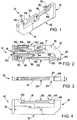
- the liquid handling device 10 shown in Figs. 1-4 falls outside the scope of the invention defined by the enclosed claims, but includes features that can form part of a device falling within the scope of the claims, and so is useful for understanding the invention.
- the liquid handling device generally comprises a housing 12 having opposite end portions 14 and 16, herein referred to as first end portion 14 and second end portion 16, forming a window where a plunger 18 and a barrel 20 are disposed.
- the first end portion 14 includes a recess 15 that opens to a rear of the second end portion 16, the recess providing an access to at least one fastener 17 that secures the first end portion to the second end portion.
- the barrel 20 is provided with an end connector 22 having a knurled surface 24 for hand screwing and a threaded portion 26 configured to be received in a threaded bore 28 in the housing 12.
- the barrel receives the plunger 18 at an opposite end from the connector 22, and the plunger 18 is pivotally connected to a carriage 30 by a pin 32.
- the carriage 30 is configured to drive the plunger 18 in a bore of the barrel 20 for aspirating/dispensing fluid in/out of the barrel and from/to a fluid component ( Fig. 7 , numeral 74), such as a syringe needle.
- the syringe needle 74 is connected to a port 34 in the first end portion 14 and receives/delivers fluid from/to the barrel 20 via a passage 36 in the first end portion 14.
- the barrel 20 may be easily replaced by a barrel having the same or different diameter with a different volume, as shown in Figs. 5 and 6 .
- the barrels may have, for example, a 5 microlitre to a 5 millilitre liquid volume and a 30 mm stroke length.
- the barrel 20 can be replaced by unscrewing the end connector 22 from the threaded bore 28, and once the end connector is clear of the first end portion 14, the barrel can be pivoted out of a plane of the housing 12. Then the barrel 20 can be removed and another barrel, such as barrel 40 or 42 can be coupled to the plunger 18 and secured to the housing 12 as described above.
- the plunger 18 and the barrel 20 may both be removed and replaced by another plunger and barrel having the same or different diameters, such as by plunger 44 and barrel 40 or by plunger 46 and barrel 42, and the replacement plunger and barrel may be coupled to carriage 30 and secured to the housing 12 as described above.
- the liquid handling device 10 includes in the second end portion 16 a drive mechanism 50 including a motive device, such as an electric rotary motor 52 connected by gears to a rotary-to-linear motion transfer device including a rotating drive screw 54 in mesh with the carriage 30, preferably by means of a nut forming part of the carriage.
- the rotating drive screw 54 extends parallel to the movement direction of the plunger 18 and effects rotation of the plunger 18.
- the drive screw 54 may be coplanar with the motor 52 and may be laterally offset and at least partially coextensive with the plunger 18.
- the carriage 30 is constrained from rotation by a guide slot 56 in the housing 12 and the carriage 30 linearly drives the plunger 18.
- the liquid handling device 10 also includes in the second end portion 16 onboard electronics 60 for controlling the motor 52 and for communicating with an external component.
- the electronics may include a printed circuit board 62 and external connectors 64 and 66 preferably at a backside of the housing 12. The connectors are provided to connect with an external component for receiving instructions for controlling the device, such as dispersing a certain amount of fluid, aspirating a certain amount of fluid, etc.
- the electronics may be onboard as shown, may be off-board as described below, or be both onboard and off-board.
- the liquid handling device 10 may have wireless communications and therefore also include an onboard power source (not shown). Additionally or alternatively, the device 10 may be tethered to an off-board power source in any suitable manner.
- the liquid handling device 10 has a thickness X.
- the thickness X correlates to the spacing between wells of a titration plate which the liquid handling device is intended to be used with.
- Conventional wells are on 9 mm and 4.5 mm centres, hence the thickness X may be no greater than 9 mm in one example and 4.5 mm in another example.
- Fig. 7 where a plurality of liquid handling devices are shown in side by side relation to one another, forming a bank of liquid handling devices.
- the bank of liquid handling devices is assembled at a centre-to-centre spacing of X.
- the plurality of liquid handling devices 10 have an electronic control module 68 removably mounted to the housings of the bank of devices 10.
- the electronic control module 68 has a plurality of plug-together mating connectors 70, 72 that mate with respective plug-together mating connectors 64, 66 on the devices 10 for electrically connecting the electronic control module 68 to electrical circuitry in the respective housings 12.
- the module 68 may be disposed in rear portions of the housings 12.
- the electronic control module 68 when the electronic control module 68 is coupled to the devices 10, the devices and control module still have a thickness less than or equal to nX, n being the number of devices 10 in the bank.
- the electronic control module 68 may be used in conjunction with or in place of the onboard electronics 60, and may provide motor control, communications and power to the devices 10.
- the control module may also include a power reduction circuit to reduce heat generation.
- each device 10 may have a respective electronic control module 76 removably mounted to the housing 12.
- the electronic control module 76 and the housing 12 have respective plug-together mating connectors 78, 80 and 64, 66 for electrically connecting the electronic control module to electrical circuitry in the housing.
- the module 76 may be disposed in a rear portion of the housing 12.
- the module 76 forms in essence part of the housing 12 but still is removable. It will be appreciated that when the electronic control module 76 is coupled to the device 10, the device and control module still have a thickness less than or equal to x.
- the electronic control module 76 may be used in conjunction with or in place of the onboard electronics 60, and may provide motor control, communications and power to the device 10.
- each device 10 may have a respective onboard miniaturized electronic motor control 82 with a communications input.
- the motor control 82 is configured to mate with a communication module 84 via a connector 86.
- the communication module 84 is a communication converter module to allow use of various standardized communications protocols, which may be wired or wireless protocols.
- the communication wires to each device 10 may be daisy chained to reduce wire count.
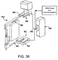
- each device 10 may mate with the communication module 84 as described above, and may also have the capability to operate aspirate or dispense sequences while in a mobile gripper 88 and/or in a docking station 90.
- the gripper 88 and docking station 90 have contacts 92 and 94 that mate with contacts 96 and 98 on the outside of the housing 12.
- the contacts 92 and 94 are electrically isolated and provide power and communication signals to the device 10 via the contacts 96 and 98. In this way, the device 10 may have pick-up and drop-off features incorporated therein.
- FIG. 11-13 another exemplary liquid handling device is shown as reference numeral 100.
- the liquid handling device 100 shown in Figs. 11-13 falls outside the scope of the invention defined by the enclosed claims, but includes features that can form part of a device falling within the scope of the claims, and so is useful for understanding the invention.
- This device 100 is the same as the device 10 shown in Figs. 1-4 except as noted below, and accordingly, the same reference numerals are being used to describe like components.
- the liquid handling device 100 is configured to function as a syringe pump, and accordingly includes a valve 102, such as a solenoid valve, disposed in the first end portion 14.
- the device 100 may include electronics 60 (or additional electronics) that can allow for pulse-width-modulated valve control for heat reduction and power conservation.
- the valve 102 has a first port 104 connected to the syringe needle 74 via port 34, a second port 106 connected to the barrel 20, and a third port 108 connected to an inlet 110 that provides for connection of the liquid handling device 100 to a source of or reservoir for a liquid.
- the device 100 includes flow passages 112, 114 and 116 that are connected to the ports 104, 106 and 108 and the port 34, barrel 20 and inlet 110, respectively.
- the bore 28 to which the barrel is coupled is the common port C of the liquid handling device 100
- the port 34 is the normally closed port N/C
- the inlet 110 is the normally open port N/O.
- the valve 102 may be coplanar with the motor 52 and electronics 60 and may be longitudinally displaced from the motor and electronics. Accordingly, as discussed above, the valve 102, together with the plunger 18, motor 52 and electronics 60 are assembled together in an imaginary envelope having a thickness no greater than X.
- the liquid handling device 100 may also include a cutout 118 for the valve 102 in the first end portion 14.
- the cutout provides an access to the at least one fastener 17 that secures the first end portion 14 to the second end portion 16.
- the valve 102 can be installed in the cutout and secured by suitable fasteners, such as fasteners 120 and 122.
- the cutout 118 may then be closed on a side by a plate and on a back wall by a back plate, which may be secured in any suitable manner.
- the cutout 118 may be closed on the side and the back wall by a single plate.
- Figs. 14-20 another exemplary liquid handling device 100 is shown.
- the liquid handling device 100 falls outside the scope of the invention defined by the enclosed claims, but includes features that can form part of a device falling within the scope of the claims, and so is useful for understanding the invention.
- the passages 112 and 114 are crossed. Accordingly, the first port 104 is connected to the barrel 20 and the second port 106 is connected to the syringe needle 74 via port 34.
- This configuration is provided to allow for user reagent addition.
- the bore 28 to which the barrel is coupled is the normally closed port N/C
- the port 34 is the common port C
- the inlet 110 remains the normally open port N/O.
- a user reagent addition pump 124 is provided that is coupled by a supply line 126 to the inlet 110.
- the supply line may run through a bore in the housing 12 or may run along an outside of the housing.
- the syringe 74 is filled with a sample from a sample container 128 and the sample is held in the barrel 20.
- reagents or diluents from the pump 124 are added into a different sample container 130.
- the sample is delivered from the barrel 20 through the syringe 74 and added to the reagents or diluents in sample container 130.
- the sample and reagents or diluents may optionally be mixed, for example by drawing the sample and reagents or diluents into the barrel 20 and then returning the mixture to the sample container 130.
- the mixing step may be repeated if desired.
- FIG. 21 another embodiment of the invention is shown wherein the liquid handling device 100 is mated with the communication module 84 as discussed above in Fig. 9 .
- the liquid handling device 100 is mated with the electronic control module 76 as discussed above in Fig. 8 .
- the liquid handling device 100 also includes a detachable reservoir 132.
- the inclusion of the reservoir can reduce fluidic complexity verses traditional liquid handling systems and can increase sample handling throughput.
- the reservoir may include a sample cartridge 134 that can have various volumes of various liquids.
- the cartridge 134 may be removable, reusable or disposable, and may be traceable, for example by barcode 136.
- the cartridge 134 may be coupled to the inlet 110 via a supply line 138.
- Fig. 23 a further embodiment is shown that is similar to Fig. 22 , but which may also have the capability to operate aspirate or dispense sequences while in a mobile gripper 88 and/or in a docking station 90, as described above in Fig. 10 .
- FIG. 2431 another exemplary embodiment of a liquid handling device is shown as reference numeral 140.
- This device 140 is similar to the device 10 shown in Figs. 1-4 except as noted below, and accordingly, the same reference numerals are being used to describe like components.
- the device 140 includes a barrel, plunger and drive assembly, which can be the same as that shown in Figs. 1-4 , assembled together in an envelope having a front portion 142 including at least the barrel and plunger.
- the plunger 18 may be coupled to the carriage 30 as described above or may be coupled to the front portion in any other suitable manner.
- the envelope includes a rear portion 144 including at least a portion of electronics 143, which may be unitary with the housing 12.
- the electronics 143 can include a motor control board 145 and an adaptor board 146 to provide motor control and communications.
- the motor control board 145 includes a connector 147 coupled to the adaptor board, such as by soldering pins of the connector to the board 146.
- the electronics also include a connector 148, which can provide a 6-wire connection to a remote controller or network for receiving communications to and/or from the device and for providing power to the device.
- the electronics may be similar to the electronics discussed above in Fig. 1 or included in an electronic control module removably mounted to the housing 12 and contained within the envelope, as discussed above regarding Fig. 8 .
- the rear portion 144 has a thickness greater than X but no greater than 2X
- the front portion has a thickness no greater than X and is laterally offset relative to a centre plane of the envelope.
- the liquid handling device 140 can be assembled with another reversely oriented liquid handling device at a centre-to-centre spacing of X and a total combined width no greater than 2X.
- any suitable electronics having a thickness no greater than 2X may be used, such as commercially available electronics.
- eight reversely oriented liquid handling devices 140 are provided. If the devices are to be wired, all wires associated with communication can be daisy chained to reduce the wire count.
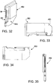
- FIG. 32-35 another exemplary embodiment of a liquid handling device is shown as reference numeral 150.
- This device 150 is the same as the device 130 shown in Figs. 24-31 except the device 150 includes a valve 102, a portion of which is shown through plate 152 suitably coupled to the housing 12.
- the device 150 is also longer than the device 130 to provide space for the valve without increasing the thickness of the device 150.
- the valve may be oriented as shown in Figs. 11-13 or as shown in Figs. 14-16 .
- the liquid handling device 140 may mate with the communication module 84 as described above in Fig. 9 , and may operate while in a mobile gripper 88 and/or in a docking station 90 as described above in Fig. 10 .
- the liquid handling device may mate with the communication module 84 as described above in Fig. 9 , and may operate while in a mobile gripper 88 and/or in a docking station 90 as described above in Fig. 10 .
- liquid handling devices may be coupled to a suitably programmed computer and/or computer network for executing command signals for carrying out the required operations.
Landscapes
- Health & Medical Sciences (AREA)
- Engineering & Computer Science (AREA)
- Life Sciences & Earth Sciences (AREA)
- General Health & Medical Sciences (AREA)
- Public Health (AREA)
- Chemical & Material Sciences (AREA)
- Biomedical Technology (AREA)
- Heart & Thoracic Surgery (AREA)
- Hematology (AREA)
- Vascular Medicine (AREA)
- Animal Behavior & Ethology (AREA)
- Anesthesiology (AREA)
- Veterinary Medicine (AREA)
- Mechanical Engineering (AREA)
- General Engineering & Computer Science (AREA)
- Clinical Laboratory Science (AREA)
- Chemical Kinetics & Catalysis (AREA)
- Physics & Mathematics (AREA)
- Analytical Chemistry (AREA)
- Biochemistry (AREA)
- General Physics & Mathematics (AREA)
- Immunology (AREA)
- Pathology (AREA)
- Automatic Analysis And Handling Materials Therefor (AREA)
- Reciprocating Pumps (AREA)
Claims (15)
- Eine Flüssigkeitshandhabungsvorrichtung (100), insbesondere eine Spritzenpumpe, zur Verwendung in einem Flüssigkeitshandhabungssystem, das eine Vielzahl der Flüssigkeitshandhabungsvorrichtungen aufweist, die in einer Nebeneinanderanordnung mit einem Mittenabstand von X zusammengesetzt sind, wobei die Vorrichtung umfasst:einen Zylinder (20),einen Kolben (18), der zum Abgeben oder Ansaugen von Flüssigkeit aus dem oder in den Zylinder im Zylinder bewegbar ist,eine elektrisch betriebene Antriebsvorrichtung (52) zum Bewegen des Kolbens in dem Zylinder zum Abgeben oder Ansaugen von Flüssigkeit aus dem oder in den Zylinder, undElektronik (84, 143) zum Steuern der Antriebsvorrichtung und zum Kommunizieren mit einer externen Komponente,wobei der Zylinder, der Kolben, die Antriebsvorrichtung und die Elektronik in einer Hülle zusammengesetzt sind, die einen Vorderabschnitt (142), der zumindest den Zylinder und den Kolben umfasst, und einen Hinterabschnitt (144) aufweist, der zumindest einen Teil der Elektronik umfasst,dadurch gekennzeichnet, dass der Hinterabschnitt eine Dicke aufweist, die größer als X aber nicht größer als 2X ist, und dass der Vorderabschnitt eine Dicke aufweist, die nicht größer als X ist, und der seitlich versetzt bezogen auf eine Mittelebene der Hülle ist, wodurch die Flüssigkeitshandhabungsvorrichtung mit einer anderen, gegenläufig ausgerichteten Flüssigkeitshandhabungsvorrichtung in einem Mittenabstand von X und einer kombinierten Gesamtbreite, die nicht größer als 2X ist, zusammengesetzt werden kann.
- Die Flüssigkeitshandhabungsvorrichtung (100) nach Anspruch 1, wobei der Zylinder (20) und die Antriebsvorrichtung (52) in einem Gehäuse (12) angeordnet sind.
- Die Flüssigkeitshandhabungsvorrichtung (100) nach Anspruch 2, wobei die Elektronik (84, 163) in einem Elektronikmodul (68) angeordnet ist, das abnehmbar am Gehäuse (12) befestigt und in der Hülle (12) untergebracht ist.
- Die Flüssigkeitshandhabungsvorrichtung (100) nach Anspruch 2, wobei die Elektronik (84, 163) eine miniaturisierte elektronische On-Board-Motorsteuerung (82) mit einem Kommunikationseingang umfasst, wobei die Motorsteuerung derart eingerichtet ist, dass sie mit einem abnehmbar am Gehäuse (12) befestigten und in der Hülle untergebrachten Kommunikationsmodul (84) zusammenpasst, und wobei das Gehäuse Kontakte (96, 98) umfasst, die derart eingerichtet sind, dass sie mit Kontakten (92, 94) an einem Greifer (88) und einer Dockingstation (90) zusammenpassen, wobei der Greifer und/oder die Dockingstation es der Vorrichtung ermöglichen, Ansaug- oder Abgabesequenzen durchzuführen.
- Die Flüssigkeitshandhabungsvorrichtung (100) nach einem der vorhergehenden Ansprüche, wobei der Teil der Elektronik (143) einheitlich mit dem Gehäuse (12) ist.
- Die Flüssigkeitshandhabungsvorrichtung (100) nach einem der vorhergehenden Ansprüche, wobei die Flüssigkeitshandhabungsvorrichtung und die gegenläufig ausgerichtete Flüssigkeitshandhabungsvorrichtung Kommunikationsleitungen umfassen, die, um die Anzahl der Leitungen zu reduzieren, miteinander verkettet sind.
- Die Flüssigkeitshandhabungsvorrichtung (100) nach einem der vorhergehenden Ansprüche, ferner umfassend ein Abgabe-/Ansauglumen, insbesondere eine Spritzennadel (74).
- Die Flüssigkeitshandhabungsvorrichtung (100) nach einem der vorhergehenden Ansprüche, ferner umfassend ein Ventil (102), das in der Hülle untergebracht ist, und wobei die Elektronik (84, 143) den Betrieb des Ventils steuert.
- Die Flüssigkeitshandhabungsvorrichtung (100) nach Anspruch 8, wobei das Ventil (102) einen mit einem Abgabe-/Ansauglumen, insbesondere einer Spritzennadel (74), verbundenen ersten Anschluss (104), einen mit dem Zylinder (20) verbundenen zweiten Anschluss (106) und einen mit einem Einlass (110) verbundenen dritten Anschluss (108) aufweist, wobei der Einlass (110) eine Verbindung der Flüssigkeitshandhabungsvorrichtung mit einer Quelle einer oder einem Reservoir für eine Flüssigkeit bereitstellt.
- Die Flüssigkeitshandhabungsvorrichtung (100) nach Anspruch 8, wobei das Ventil (102) einen mit dem Zylinder (20) verbundenen ersten Anschluss (104), einen mit einem Abgabe-/Ansauglumen, insbesondere einer Spritzennadel (74), verbundenen zweiten Anschluss (106) und einen mit einem Einlass (110) verbundenen dritten Anschluss (108) aufweist, wobei der Einlass (110) eine Verbindung der Flüssigkeitshandhabungsvorrichtung mit einer Quelle einer oder einem Reservoir für eine Flüssigkeit bereitstellt, und ferner umfassend eine Benutzerreagenzadditionspumpe (124), die über eine Versorgungsleitung (126) mit dem Einlass gekoppelt ist.
- Die Flüssigkeitshandhabungsvorrichtung (100) nach einem der vorhergehenden Ansprüche, wobei der Zylinder (20) abnehmbar am Gehäuse (12) der Flüssigkeitshandhabungsvorrichtung, die von der Hülle eingegrenzt ist, befestigt ist.
- Die Flüssigkeitshandhabungsvorrichtung (100) nach einem der vorhergehenden Ansprüche, wobei die Spritzennadel (74) abnehmbar an dem Zylinder (20) oder einem Gehäuse (12), mit dem der Zylinder verbunden ist, verbunden ist.
- Die Flüssigkeitshandhabungsvorrichtung (100) nach einem der vorhergehenden Ansprüche, wobei X einen Wert von 9 mm hat.
- Die Flüssigkeitshandhabungsvorrichtung (100) nach einem der Ansprüche 1 bis 12, wobei X einen Wert von 4,5 mm hat.
- Ein Flüssigkeitshandhabungssystem, das zwei, drei, vier oder mehr der Flüssigkeitshandhabungsvorrichtungen (100) nach einem der vorhergehenden Ansprüche umfasst, die in einer Nebeneinanderanordnung mit einem Mittenabstand von X zusammengesetzt sind.
Applications Claiming Priority (2)
| Application Number | Priority Date | Filing Date | Title |
|---|---|---|---|
| US35155010P | 2010-06-04 | 2010-06-04 | |
| PCT/US2011/039264 WO2011153526A2 (en) | 2010-06-04 | 2011-06-06 | Miniaturized syringe pump system and modules |
Publications (2)
| Publication Number | Publication Date |
|---|---|
| EP2577320A2 EP2577320A2 (de) | 2013-04-10 |
| EP2577320B1 true EP2577320B1 (de) | 2019-04-17 |
Family
ID=44314996
Family Applications (1)
| Application Number | Title | Priority Date | Filing Date |
|---|---|---|---|
| EP11724932.6A Active EP2577320B1 (de) | 2010-06-04 | 2011-06-06 | Miniatur-spritzenpumpensystem und module |
Country Status (3)
| Country | Link |
|---|---|
| US (1) | US9470215B2 (de) |
| EP (1) | EP2577320B1 (de) |
| WO (1) | WO2011153526A2 (de) |
Families Citing this family (4)
| Publication number | Priority date | Publication date | Assignee | Title |
|---|---|---|---|---|
| DE102012015083B3 (de) * | 2012-07-30 | 2013-08-08 | Scienion Ag | Dispenserkopf mit mehreren verschiebbaren Dispensern |
| US10564172B2 (en) | 2014-05-08 | 2020-02-18 | The Cleveland Clinic Foundation | Systems and methods for detection, analysis, isolation and/or harvesting of biological objects |
| EP3843812A4 (de) * | 2018-08-27 | 2022-06-29 | Dana-Farber Cancer Institute, Inc. | Modularer radiomarkierender tracer-synthesizer |
| US12603554B2 (en) | 2023-06-06 | 2026-04-14 | Precision Engine Controls Corporation | Systems, assemblies, and methods associated with a replaceable motor controller |
Family Cites Families (25)
| Publication number | Priority date | Publication date | Assignee | Title |
|---|---|---|---|---|
| US4087248A (en) * | 1976-07-26 | 1978-05-02 | Miles Laughton E | Multiple assay machine and method |
| US4424720A (en) | 1980-12-15 | 1984-01-10 | Ivac Corporation | Mechanism for screw drive and syringe plunger engagement/disengagement |
| US4435173A (en) * | 1982-03-05 | 1984-03-06 | Delta Medical Industries | Variable rate syringe pump for insulin delivery |
| US4547189A (en) | 1984-03-05 | 1985-10-15 | John A. Long | Insulin syringe injector apparatus with auto-aspirator feature |
| US4846797A (en) * | 1985-05-14 | 1989-07-11 | Intelligent Medicine, Inc. | Syringe positioning device for enhancing fluid flow control |
| JPH031315A (ja) | 1989-05-29 | 1991-01-08 | Fuji Photo Film Co Ltd | 磁気記録媒体 |
| US5097122A (en) | 1990-04-16 | 1992-03-17 | Pacesetter Infusion, Ltd. | Medication infusion system having optical motion sensor to detect drive mechanism malfunction |
| CA2384523C (en) * | 1991-03-04 | 2007-01-09 | Bayer Corporation | Automated analyzer |
| US5505709A (en) | 1994-09-15 | 1996-04-09 | Minimed, Inc., A Delaware Corporation | Mated infusion pump and syringe |
| JPH09101315A (ja) * | 1995-10-03 | 1997-04-15 | Suzuki Motor Corp | 分注装置 |
| ZA9811087B (en) * | 1997-12-04 | 1999-06-03 | Bracco Research Sa | Automatic liquid injection system and method |
| EP1451674A4 (de) | 2001-10-26 | 2008-08-20 | Sequenom Inc | Verfahren und vorrichtung zur parallelen ausgabe definierter volumen von festpartikeln |
| AU2003251996A1 (en) | 2002-07-23 | 2004-02-09 | Protedyne Corporation | Liquid handling tool having hollow plunger |
| US7128727B2 (en) * | 2002-09-30 | 2006-10-31 | Flaherty J Christopher | Components and methods for patient infusion device |
| JP4102863B2 (ja) * | 2003-02-14 | 2008-06-18 | 株式会社スタックシステム | 分注機及び分注装置 |
| CA2554503C (en) | 2004-03-19 | 2009-06-23 | Medtronic Minimed, Inc. | Lead screw driven syringe with an integral split plunger nut and method of using the same |
| CH701163B1 (de) | 2004-06-24 | 2010-12-15 | Tecan Trading Ag | System zum Manipulieren von Flüssigkeitsproben sowie Vorrichtung und Verfahren zum Anordnen von Pipetten- oder Dispenserspitzen in einem solchen System. |
| US8057756B2 (en) * | 2005-01-28 | 2011-11-15 | Parker-Hannifin Corporation | Sampling probe, gripper and interface for laboratory sample management systems |
| WO2006089103A1 (en) | 2005-02-18 | 2006-08-24 | Kalypsys, Inc. | Automated evaluation of target samples in a high performance analysis system |
| US7905868B2 (en) | 2006-08-23 | 2011-03-15 | Medtronic Minimed, Inc. | Infusion medium delivery device and method with drive device for driving plunger in reservoir |
| US8192698B2 (en) | 2006-01-27 | 2012-06-05 | Parker-Hannifin Corporation | Sampling probe, gripper and interface for laboratory sample management systems |
| EP2017477A1 (de) * | 2007-07-19 | 2009-01-21 | The Automation Partnership (Cambridge) Limited | Vorrichtung zum automatisierten Pumpen |
| US8658110B2 (en) | 2007-08-13 | 2014-02-25 | Hewlett-Packard Development Company, L.P. | Fluid delivery system |
| US20090104078A1 (en) * | 2007-10-18 | 2009-04-23 | Matrix Technologies Corporation | Apparatus and method for dispensing small volume liquid samples |
| US7806868B2 (en) * | 2007-11-30 | 2010-10-05 | Roche Diagnostics Operations, Inc. | Drug reservoir loading and unloading mechanism for a drug delivery device using a unidirectional rotated shaft |
-
2011
- 2011-06-06 US US13/701,853 patent/US9470215B2/en not_active Expired - Fee Related
- 2011-06-06 EP EP11724932.6A patent/EP2577320B1/de active Active
- 2011-06-06 WO PCT/US2011/039264 patent/WO2011153526A2/en not_active Ceased
Non-Patent Citations (1)
| Title |
|---|
| None * |
Also Published As
| Publication number | Publication date |
|---|---|
| US9470215B2 (en) | 2016-10-18 |
| WO2011153526A3 (en) | 2012-04-19 |
| EP2577320A2 (de) | 2013-04-10 |
| WO2011153526A2 (en) | 2011-12-08 |
| US20130129538A1 (en) | 2013-05-23 |
Similar Documents
| Publication | Publication Date | Title |
|---|---|---|
| US9079178B2 (en) | Apparatus and methods for pipetting with interchangeability among different pipette tips | |
| EP2193848B1 (de) | Modulare Pipettiereinheit, Pipettiervorrichtung, Pipettiersystem und Pipettierverfahren zum Pipettieren von Fluidproben | |
| CN109152992A (zh) | 具有用于模块化的独立致动的移液管通道的歧管安装件的液体分配器 | |
| US8192698B2 (en) | Sampling probe, gripper and interface for laboratory sample management systems | |
| US8057756B2 (en) | Sampling probe, gripper and interface for laboratory sample management systems | |
| CA3027643C (en) | Smart microfluidic mixing instrument and cartridges | |
| US20070180935A1 (en) | Automated pipette machine | |
| US9470215B2 (en) | Miniaturized syringe pump system and modules | |
| CN111443214A (zh) | 一种电动移液设备 | |
| CN217699236U (zh) | 移液机构及液体工作站 | |
| CN111394243A (zh) | 微流控芯片核酸检测装置 | |
| CN110193388A (zh) | 一种多通道自动移液枪 | |
| CN212855810U (zh) | 移液操作装置 | |
| US11253850B2 (en) | Pipette dispenser tip utilizing print head | |
| EP2983823B1 (de) | Verteilerantrieb | |
| EP4458468A1 (de) | Module für flüssigkeitshandhabungsanwendungen | |
| JP7581403B2 (ja) | 多機能ピペット及び自動検査機 | |
| EP4517333A1 (de) | Dosierwerkzeug und dosiersystem zur automatisierten flüssigkeitshandhabung | |
| CN113833621B (zh) | 一种大通量可远程控制的高精度计量泵 | |
| CN215515562U (zh) | 传输定位系统 | |
| EP0404321A2 (de) | Durch Nocken gesteuertes Strömungssystem zur Benutzung mit Analyseapparaten | |
| JP2005502884A (ja) | 液体ハンドリングシステムのための2次液体ディスペンシングモジュール | |
| CN115739223A (zh) | 移液筒及移液器 | |
| CN116440761A (zh) | 混匀装置 | |
| EP4630165A1 (de) | Flüssigkeitstransfer |
Legal Events
| Date | Code | Title | Description |
|---|---|---|---|
| PUAI | Public reference made under article 153(3) epc to a published international application that has entered the european phase |
Free format text: ORIGINAL CODE: 0009012 |
|
| 17P | Request for examination filed |
Effective date: 20130102 |
|
| AK | Designated contracting states |
Kind code of ref document: A2 Designated state(s): AL AT BE BG CH CY CZ DE DK EE ES FI FR GB GR HR HU IE IS IT LI LT LU LV MC MK MT NL NO PL PT RO RS SE SI SK SM TR |
|
| DAX | Request for extension of the european patent (deleted) | ||
| STAA | Information on the status of an ep patent application or granted ep patent |
Free format text: STATUS: EXAMINATION IS IN PROGRESS |
|
| 17Q | First examination report despatched |
Effective date: 20170601 |
|
| GRAP | Despatch of communication of intention to grant a patent |
Free format text: ORIGINAL CODE: EPIDOSNIGR1 |
|
| STAA | Information on the status of an ep patent application or granted ep patent |
Free format text: STATUS: GRANT OF PATENT IS INTENDED |
|
| INTG | Intention to grant announced |
Effective date: 20181116 |
|
| GRAS | Grant fee paid |
Free format text: ORIGINAL CODE: EPIDOSNIGR3 |
|
| GRAA | (expected) grant |
Free format text: ORIGINAL CODE: 0009210 |
|
| STAA | Information on the status of an ep patent application or granted ep patent |
Free format text: STATUS: THE PATENT HAS BEEN GRANTED |
|
| AK | Designated contracting states |
Kind code of ref document: B1 Designated state(s): AL AT BE BG CH CY CZ DE DK EE ES FI FR GB GR HR HU IE IS IT LI LT LU LV MC MK MT NL NO PL PT RO RS SE SI SK SM TR |
|
| REG | Reference to a national code |
Ref country code: GB Ref legal event code: FG4D |
|
| REG | Reference to a national code |
Ref country code: CH Ref legal event code: EP Ref country code: CH Ref legal event code: NV Representative=s name: E. BLUM AND CO. AG PATENT- UND MARKENANWAELTE , CH |
|
| REG | Reference to a national code |
Ref country code: DE Ref legal event code: R096 Ref document number: 602011058119 Country of ref document: DE |
|
| REG | Reference to a national code |
Ref country code: AT Ref legal event code: REF Ref document number: 1122158 Country of ref document: AT Kind code of ref document: T Effective date: 20190515 Ref country code: IE Ref legal event code: FG4D |
|
| REG | Reference to a national code |
Ref country code: NL Ref legal event code: MP Effective date: 20190417 |
|
| REG | Reference to a national code |
Ref country code: LT Ref legal event code: MG4D |
|
| PG25 | Lapsed in a contracting state [announced via postgrant information from national office to epo] |
Ref country code: NL Free format text: LAPSE BECAUSE OF FAILURE TO SUBMIT A TRANSLATION OF THE DESCRIPTION OR TO PAY THE FEE WITHIN THE PRESCRIBED TIME-LIMIT Effective date: 20190417 |
|
| PG25 | Lapsed in a contracting state [announced via postgrant information from national office to epo] |
Ref country code: FI Free format text: LAPSE BECAUSE OF FAILURE TO SUBMIT A TRANSLATION OF THE DESCRIPTION OR TO PAY THE FEE WITHIN THE PRESCRIBED TIME-LIMIT Effective date: 20190417 Ref country code: LT Free format text: LAPSE BECAUSE OF FAILURE TO SUBMIT A TRANSLATION OF THE DESCRIPTION OR TO PAY THE FEE WITHIN THE PRESCRIBED TIME-LIMIT Effective date: 20190417 Ref country code: SE Free format text: LAPSE BECAUSE OF FAILURE TO SUBMIT A TRANSLATION OF THE DESCRIPTION OR TO PAY THE FEE WITHIN THE PRESCRIBED TIME-LIMIT Effective date: 20190417 Ref country code: HR Free format text: LAPSE BECAUSE OF FAILURE TO SUBMIT A TRANSLATION OF THE DESCRIPTION OR TO PAY THE FEE WITHIN THE PRESCRIBED TIME-LIMIT Effective date: 20190417 Ref country code: PT Free format text: LAPSE BECAUSE OF FAILURE TO SUBMIT A TRANSLATION OF THE DESCRIPTION OR TO PAY THE FEE WITHIN THE PRESCRIBED TIME-LIMIT Effective date: 20190817 Ref country code: NO Free format text: LAPSE BECAUSE OF FAILURE TO SUBMIT A TRANSLATION OF THE DESCRIPTION OR TO PAY THE FEE WITHIN THE PRESCRIBED TIME-LIMIT Effective date: 20190717 Ref country code: AL Free format text: LAPSE BECAUSE OF FAILURE TO SUBMIT A TRANSLATION OF THE DESCRIPTION OR TO PAY THE FEE WITHIN THE PRESCRIBED TIME-LIMIT Effective date: 20190417 Ref country code: ES Free format text: LAPSE BECAUSE OF FAILURE TO SUBMIT A TRANSLATION OF THE DESCRIPTION OR TO PAY THE FEE WITHIN THE PRESCRIBED TIME-LIMIT Effective date: 20190417 |
|
| PG25 | Lapsed in a contracting state [announced via postgrant information from national office to epo] |
Ref country code: RS Free format text: LAPSE BECAUSE OF FAILURE TO SUBMIT A TRANSLATION OF THE DESCRIPTION OR TO PAY THE FEE WITHIN THE PRESCRIBED TIME-LIMIT Effective date: 20190417 Ref country code: BG Free format text: LAPSE BECAUSE OF FAILURE TO SUBMIT A TRANSLATION OF THE DESCRIPTION OR TO PAY THE FEE WITHIN THE PRESCRIBED TIME-LIMIT Effective date: 20190717 Ref country code: LV Free format text: LAPSE BECAUSE OF FAILURE TO SUBMIT A TRANSLATION OF THE DESCRIPTION OR TO PAY THE FEE WITHIN THE PRESCRIBED TIME-LIMIT Effective date: 20190417 Ref country code: GR Free format text: LAPSE BECAUSE OF FAILURE TO SUBMIT A TRANSLATION OF THE DESCRIPTION OR TO PAY THE FEE WITHIN THE PRESCRIBED TIME-LIMIT Effective date: 20190718 Ref country code: PL Free format text: LAPSE BECAUSE OF FAILURE TO SUBMIT A TRANSLATION OF THE DESCRIPTION OR TO PAY THE FEE WITHIN THE PRESCRIBED TIME-LIMIT Effective date: 20190417 |
|
| REG | Reference to a national code |
Ref country code: AT Ref legal event code: MK05 Ref document number: 1122158 Country of ref document: AT Kind code of ref document: T Effective date: 20190417 |
|
| PG25 | Lapsed in a contracting state [announced via postgrant information from national office to epo] |
Ref country code: IS Free format text: LAPSE BECAUSE OF FAILURE TO SUBMIT A TRANSLATION OF THE DESCRIPTION OR TO PAY THE FEE WITHIN THE PRESCRIBED TIME-LIMIT Effective date: 20190817 |
|
| REG | Reference to a national code |
Ref country code: DE Ref legal event code: R097 Ref document number: 602011058119 Country of ref document: DE |
|
| PG25 | Lapsed in a contracting state [announced via postgrant information from national office to epo] |
Ref country code: SK Free format text: LAPSE BECAUSE OF FAILURE TO SUBMIT A TRANSLATION OF THE DESCRIPTION OR TO PAY THE FEE WITHIN THE PRESCRIBED TIME-LIMIT Effective date: 20190417 Ref country code: EE Free format text: LAPSE BECAUSE OF FAILURE TO SUBMIT A TRANSLATION OF THE DESCRIPTION OR TO PAY THE FEE WITHIN THE PRESCRIBED TIME-LIMIT Effective date: 20190417 Ref country code: DK Free format text: LAPSE BECAUSE OF FAILURE TO SUBMIT A TRANSLATION OF THE DESCRIPTION OR TO PAY THE FEE WITHIN THE PRESCRIBED TIME-LIMIT Effective date: 20190417 Ref country code: MC Free format text: LAPSE BECAUSE OF FAILURE TO SUBMIT A TRANSLATION OF THE DESCRIPTION OR TO PAY THE FEE WITHIN THE PRESCRIBED TIME-LIMIT Effective date: 20190417 Ref country code: AT Free format text: LAPSE BECAUSE OF FAILURE TO SUBMIT A TRANSLATION OF THE DESCRIPTION OR TO PAY THE FEE WITHIN THE PRESCRIBED TIME-LIMIT Effective date: 20190417 Ref country code: CZ Free format text: LAPSE BECAUSE OF FAILURE TO SUBMIT A TRANSLATION OF THE DESCRIPTION OR TO PAY THE FEE WITHIN THE PRESCRIBED TIME-LIMIT Effective date: 20190417 Ref country code: RO Free format text: LAPSE BECAUSE OF FAILURE TO SUBMIT A TRANSLATION OF THE DESCRIPTION OR TO PAY THE FEE WITHIN THE PRESCRIBED TIME-LIMIT Effective date: 20190417 |
|
| PLBE | No opposition filed within time limit |
Free format text: ORIGINAL CODE: 0009261 |
|
| STAA | Information on the status of an ep patent application or granted ep patent |
Free format text: STATUS: NO OPPOSITION FILED WITHIN TIME LIMIT |
|
| PG25 | Lapsed in a contracting state [announced via postgrant information from national office to epo] |
Ref country code: SM Free format text: LAPSE BECAUSE OF FAILURE TO SUBMIT A TRANSLATION OF THE DESCRIPTION OR TO PAY THE FEE WITHIN THE PRESCRIBED TIME-LIMIT Effective date: 20190417 Ref country code: IT Free format text: LAPSE BECAUSE OF FAILURE TO SUBMIT A TRANSLATION OF THE DESCRIPTION OR TO PAY THE FEE WITHIN THE PRESCRIBED TIME-LIMIT Effective date: 20190417 |
|
| 26N | No opposition filed |
Effective date: 20200120 |
|
| REG | Reference to a national code |
Ref country code: BE Ref legal event code: MM Effective date: 20190630 |
|
| PG25 | Lapsed in a contracting state [announced via postgrant information from national office to epo] |
Ref country code: TR Free format text: LAPSE BECAUSE OF FAILURE TO SUBMIT A TRANSLATION OF THE DESCRIPTION OR TO PAY THE FEE WITHIN THE PRESCRIBED TIME-LIMIT Effective date: 20190417 |
|
| PG25 | Lapsed in a contracting state [announced via postgrant information from national office to epo] |
Ref country code: IE Free format text: LAPSE BECAUSE OF NON-PAYMENT OF DUE FEES Effective date: 20190606 |
|
| PG25 | Lapsed in a contracting state [announced via postgrant information from national office to epo] |
Ref country code: BE Free format text: LAPSE BECAUSE OF NON-PAYMENT OF DUE FEES Effective date: 20190630 Ref country code: SI Free format text: LAPSE BECAUSE OF FAILURE TO SUBMIT A TRANSLATION OF THE DESCRIPTION OR TO PAY THE FEE WITHIN THE PRESCRIBED TIME-LIMIT Effective date: 20190417 Ref country code: LU Free format text: LAPSE BECAUSE OF NON-PAYMENT OF DUE FEES Effective date: 20190606 |
|
| PG25 | Lapsed in a contracting state [announced via postgrant information from national office to epo] |
Ref country code: CY Free format text: LAPSE BECAUSE OF FAILURE TO SUBMIT A TRANSLATION OF THE DESCRIPTION OR TO PAY THE FEE WITHIN THE PRESCRIBED TIME-LIMIT Effective date: 20190417 |
|
| PG25 | Lapsed in a contracting state [announced via postgrant information from national office to epo] |
Ref country code: HU Free format text: LAPSE BECAUSE OF FAILURE TO SUBMIT A TRANSLATION OF THE DESCRIPTION OR TO PAY THE FEE WITHIN THE PRESCRIBED TIME-LIMIT; INVALID AB INITIO Effective date: 20110606 Ref country code: MT Free format text: LAPSE BECAUSE OF FAILURE TO SUBMIT A TRANSLATION OF THE DESCRIPTION OR TO PAY THE FEE WITHIN THE PRESCRIBED TIME-LIMIT Effective date: 20190417 |
|
| PG25 | Lapsed in a contracting state [announced via postgrant information from national office to epo] |
Ref country code: MK Free format text: LAPSE BECAUSE OF FAILURE TO SUBMIT A TRANSLATION OF THE DESCRIPTION OR TO PAY THE FEE WITHIN THE PRESCRIBED TIME-LIMIT Effective date: 20190417 |
|
| PGFP | Annual fee paid to national office [announced via postgrant information from national office to epo] |
Ref country code: GB Payment date: 20220628 Year of fee payment: 12 |
|
| PGFP | Annual fee paid to national office [announced via postgrant information from national office to epo] |
Ref country code: FR Payment date: 20220627 Year of fee payment: 12 |
|
| PGFP | Annual fee paid to national office [announced via postgrant information from national office to epo] |
Ref country code: DE Payment date: 20220629 Year of fee payment: 12 |
|
| PGFP | Annual fee paid to national office [announced via postgrant information from national office to epo] |
Ref country code: CH Payment date: 20220706 Year of fee payment: 12 |
|
| P01 | Opt-out of the competence of the unified patent court (upc) registered |
Effective date: 20230524 |
|
| REG | Reference to a national code |
Ref country code: DE Ref legal event code: R119 Ref document number: 602011058119 Country of ref document: DE |
|
| REG | Reference to a national code |
Ref country code: CH Ref legal event code: PL |
|
| GBPC | Gb: european patent ceased through non-payment of renewal fee |
Effective date: 20230606 |
|
| PG25 | Lapsed in a contracting state [announced via postgrant information from national office to epo] |
Ref country code: DE Free format text: LAPSE BECAUSE OF NON-PAYMENT OF DUE FEES Effective date: 20240103 Ref country code: GB Free format text: LAPSE BECAUSE OF NON-PAYMENT OF DUE FEES Effective date: 20230606 Ref country code: CH Free format text: LAPSE BECAUSE OF NON-PAYMENT OF DUE FEES Effective date: 20230630 |
|
| PG25 | Lapsed in a contracting state [announced via postgrant information from national office to epo] |
Ref country code: FR Free format text: LAPSE BECAUSE OF NON-PAYMENT OF DUE FEES Effective date: 20230630 |