EP2577321B1 - Vorrichtung und verfahren zur restlosen aufnahme von flüssigkeiten aus gefässen - Google Patents
Vorrichtung und verfahren zur restlosen aufnahme von flüssigkeiten aus gefässen Download PDFInfo
- Publication number
- EP2577321B1 EP2577321B1 EP11730897.3A EP11730897A EP2577321B1 EP 2577321 B1 EP2577321 B1 EP 2577321B1 EP 11730897 A EP11730897 A EP 11730897A EP 2577321 B1 EP2577321 B1 EP 2577321B1
- Authority
- EP
- European Patent Office
- Prior art keywords
- vessel
- removal
- tip
- elements
- unit
- Prior art date
- Legal status (The legal status is an assumption and is not a legal conclusion. Google has not performed a legal analysis and makes no representation as to the accuracy of the status listed.)
- Active
Links
Images


Classifications
-
- B—PERFORMING OPERATIONS; TRANSPORTING
- B01—PHYSICAL OR CHEMICAL PROCESSES OR APPARATUS IN GENERAL
- B01L—CHEMICAL OR PHYSICAL LABORATORY APPARATUS FOR GENERAL USE
- B01L3/00—Containers or dishes for laboratory use, e.g. laboratory glassware; Droppers
- B01L3/02—Burettes; Pipettes
- B01L3/021—Pipettes, i.e. with only one conduit for withdrawing and redistributing liquids
-
- B—PERFORMING OPERATIONS; TRANSPORTING
- B01—PHYSICAL OR CHEMICAL PROCESSES OR APPARATUS IN GENERAL
- B01L—CHEMICAL OR PHYSICAL LABORATORY APPARATUS FOR GENERAL USE
- B01L3/00—Containers or dishes for laboratory use, e.g. laboratory glassware; Droppers
- B01L3/02—Burettes; Pipettes
-
- B—PERFORMING OPERATIONS; TRANSPORTING
- B01—PHYSICAL OR CHEMICAL PROCESSES OR APPARATUS IN GENERAL
- B01L—CHEMICAL OR PHYSICAL LABORATORY APPARATUS FOR GENERAL USE
- B01L9/00—Supporting devices; Holding devices
- B01L9/06—Test-tube stands; Test-tube holders
-
- G—PHYSICS
- G01—MEASURING; TESTING
- G01N—INVESTIGATING OR ANALYSING MATERIALS BY DETERMINING THEIR CHEMICAL OR PHYSICAL PROPERTIES
- G01N35/00—Automatic analysis not limited to methods or materials provided for in any single one of groups G01N1/00 - G01N33/00; Handling materials therefor
- G01N35/10—Devices for transferring samples or any liquids to, in, or from, the analysis apparatus, e.g. suction devices, injection devices
- G01N35/1009—Characterised by arrangements for controlling the aspiration or dispense of liquids
-
- B—PERFORMING OPERATIONS; TRANSPORTING
- B01—PHYSICAL OR CHEMICAL PROCESSES OR APPARATUS IN GENERAL
- B01L—CHEMICAL OR PHYSICAL LABORATORY APPARATUS FOR GENERAL USE
- B01L2200/00—Solutions for specific problems relating to chemical or physical laboratory apparatus
- B01L2200/06—Fluid handling related problems
- B01L2200/0642—Filling fluids into wells by specific techniques
-
- B—PERFORMING OPERATIONS; TRANSPORTING
- B01—PHYSICAL OR CHEMICAL PROCESSES OR APPARATUS IN GENERAL
- B01L—CHEMICAL OR PHYSICAL LABORATORY APPARATUS FOR GENERAL USE
- B01L2200/00—Solutions for specific problems relating to chemical or physical laboratory apparatus
- B01L2200/14—Process control and prevention of errors
- B01L2200/143—Quality control, feedback systems
- B01L2200/146—Employing pressure sensors
-
- B—PERFORMING OPERATIONS; TRANSPORTING
- B01—PHYSICAL OR CHEMICAL PROCESSES OR APPARATUS IN GENERAL
- B01L—CHEMICAL OR PHYSICAL LABORATORY APPARATUS FOR GENERAL USE
- B01L2400/00—Moving or stopping fluids
- B01L2400/04—Moving fluids with specific forces or mechanical means
- B01L2400/0475—Moving fluids with specific forces or mechanical means specific mechanical means and fluid pressure
- B01L2400/0478—Moving fluids with specific forces or mechanical means specific mechanical means and fluid pressure pistons
-
- B—PERFORMING OPERATIONS; TRANSPORTING
- B01—PHYSICAL OR CHEMICAL PROCESSES OR APPARATUS IN GENERAL
- B01L—CHEMICAL OR PHYSICAL LABORATORY APPARATUS FOR GENERAL USE
- B01L3/00—Containers or dishes for laboratory use, e.g. laboratory glassware; Droppers
- B01L3/50—Containers for the purpose of retaining a material to be analysed, e.g. test tubes
- B01L3/508—Rigid containers without fluid transport within
- B01L3/5082—Test tubes per se
-
- G—PHYSICS
- G01—MEASURING; TESTING
- G01N—INVESTIGATING OR ANALYSING MATERIALS BY DETERMINING THEIR CHEMICAL OR PHYSICAL PROPERTIES
- G01N35/00—Automatic analysis not limited to methods or materials provided for in any single one of groups G01N1/00 - G01N33/00; Handling materials therefor
- G01N35/10—Devices for transferring samples or any liquids to, in, or from, the analysis apparatus, e.g. suction devices, injection devices
Definitions
- the present invention relates to a device and a method for the complete absorption of liquids from vessels, in particular for the removal of reagents from reaction vessels by pipettes.
- robotic systems for example, liquid handling machines
- robotic systems for example, liquid handling machines
- These liquid transfer systems usually consist of withdrawal units (e.g., pipettes) which submerge from above into the generally upright vessels and draw the liquid out of the vessels.
- withdrawal units e.g., pipettes
- the sampling units have a sampling tip which is immersed in the liquid to remove the liquid.
- This tip is shaped so that a channel through which the liquid can flow is surrounded by a wall. The channel passes through the sampling unit starting at the sampling tip. If there is a negative pressure in the channel, the liquid is sucked out of the vessel. In this way, the liquid is removed.
- the extraction tip has at its end an end surface which is defined by the limiting wall.
- WO 2009/084451 A1 discloses a device for receiving liquids from vessels by means of removal units.
- the suction port for sucking the liquids is arranged on a lateral peripheral surface of the extraction unit.
- JP 55 039029 A discloses a device for receiving liquids from vessels by means of a suction tube whose front tip is chamfered.
- the suction tube is arranged centrally within the vessel.
- the bottom of the vessel is elastically supported, for example by means of polyurethane foam rubber. This makes it possible to lower the tip of the suction tube to the bottom of the vessel without the tip being deformed.
- US 6,363,802 B1 discloses a device for the precise extraction of small volumes of liquid from a sample vessel.
- the device comprises a suction probe whose tip is immersed in the liquid to be aspirated.
- the suction probe is arranged centrally in the sample vessel.
- the tip is lowered into the vessel via a drive mechanism until the tip hits the bottom of the vessel with a predictable force.
- US Pat. No. 6,270,726 B1 relates to a pipetting station with a pipetting probe and a scanning device, which allows a controlled lowering of the pipetting probe down to the bottom of the sample vessel.
- the pipetting probe is arranged centrally in the sample vessel.
- the object is achieved by the device according to claim 1 and the method according to claim 8.
- the invention relates to a device for receiving liquids from vessels by means of removal units with removal tips, the device comprising removal units with removal tips and vessels for the liquid to be removed.
- the extraction tips are shaped such that a channel, which is surrounded by a wall and begins at the extraction tip, is formed, the extraction tips having at their end an end surface which is defined by the surrounding wall.
- the device according to the invention allows the complete absorption of liquids from a vessel in which the liquid to be removed is located.
- the vessel is curved at the lower end, then it is advantageous, for example, to position the vessel under the removal unit so that the tip of the removal unit a little, ie 1/5 - 1/100 of the vessel diameter, away from the vertex of the curvature would touch the bottom of the vessel.
- a preferred embodiment also contains at least one compensation element, which is suitable for being able to avoid the extraction tip and the vessel bottom when inserting the removal tip into the vessel, the vessel or the withdrawal tip in the direction of the relative direction of movement of the removal tip and the vessel. This is the case, for example, when the vessel and / or the removal tip are spring-mounted.
- Preferred compensation elements are active or passive elements or combinations of active and passive elements.
- the vessel is domed at the bottom, then it is advantageous to position the vessel below the withdrawal unit so that the tip of the withdrawal unit is slightly inward of, e.g. 1/5 - 1/100 of the vessel diameter, from the vertex of the vault would touch the bottom of the vessel.
- a preferred embodiment also contains at least one compensation element, which is suitable for being able to avoid the extraction tip and the vessel bottom when inserting the removal tip into the vessel, the vessel or the withdrawal tip in the direction of the relative direction of movement of the removal tip and the vessel. This is the case, for example, when the vessel and / or the removal tip are spring-mounted.
- Preferred compensation elements are active or passive elements or combinations of active and passive elements.
- Preferred passive elements are springs or other resilient materials, such as resilient plastics such as foams or rubber. As springs in particular spiral or leaf springs can be used.
- the passive elements have the advantage that a compensation of the pressure on the vessel bottom and the sampling tip is easy and without additional control. When placing the sampling tip on the bottom of the vessel it automatically deviates downwards through the elastic compensation element or the sampling tip deviates upwards.
- Preferred active elements are piezo elements, muscle wires or motors which, in particular provided with respective mechanisms, cause a compensation of the pressure upon contact of the removal tip with the bottom of the vessel.
- these active elements are provided by a sensor which measures the contact pressure, and control electronics which control the deflection of the compensation element.
- An active control of the pressure between sampling tip and vessel bottom has the advantage that errors, such as tilting, can be compensated.
- the compensation elements are constructed from commercially available spring material.
- a compensation element made of elastic plastics or springs.
- the vessel on the compensation element is preferably arranged vertically or slightly inclined, wherein it is preferably held by a mounted on the compensation element holding device.
- the vessel can be detachably or non-detachably connected to the compensation element or the holding device.
- a detachable Connection has the advantage that the vessel is easily replaceable and, for example, disposable containers can be used.
- the vessel is placed only on the compensation element or the holding device.
- the compensation element is mounted on a bottom plate to ensure a firm footing of the element.
- the compensation element is arranged directly in or on the removal unit, so that the entire removal unit is elastically mounted, or a part of the wall of the removal unit consists of an elastic material or is designed as a bellows, so that at least the removal tip is elastically mounted is.
- compensation elements are arranged both on the vessel and on the removal unit.
- the compensation element is preferably arranged in a guide unit, for example a sleeve with at least one opening on the upper side.
- This guide unit has guide elements that guide the compensation element, the holding device, the vessel or the removal unit in a straight path.
- the walls of the above-mentioned sleeve form the guide elements.
- the length of the guide unit is such that it has the compensation element, preferably with holding device, particularly preferably can also accommodate at least a portion of the vessel or the removal unit.
- the guide unit is preferably fixedly mounted on the bottom plate, in particular the guide unit is screwed by means of a thread on the bottom plate.
- the compensation element is designed as a distance adjusting element which is suitable for the absorption of a liquid from the vessel by a removal unit, the relative vertical distance between the vessel bottom and tip of the extraction unit depending on the amount of liquid in the vessel to change in that the distance between the bottom of the vessel and the tip of the removal unit decreases as the removal of liquid increases.
- the tip of the extraction unit should always be below the liquid level, so that no air is sucked in.
- the extraction unit removes liquid from the vessel. Depending on the amount of fluid, this removal of fluid makes the extraction unit heavier and the vessel lighter. Incidentally, the liquid level rises in the extraction unit and drops in the vessel.
- this distance is continuously reduced by the distance adjusting element in dependence on the amount of liquid absorbed.
- the tip of the extraction unit should always be below the liquid level in the vessel.
- a measure of the withdrawn liquid may be the weight of the recorded liquid or the liquid remaining in the vessel or the liquid level in the vessel or removal unit.
- the tip of the extraction unit should not touch the bottom of the vessel, at least not until the liquid is almost completely absorbed.
- Preferred distance adjustment elements are active or passive elements or combinations of active and passive elements.
- Suitable passive elements regulate the distance between the bottom of the vessel and the tip of the removal unit, preferably by the weight of the amount of liquid contained in the vessel.
- passive distance adjustment elements regulation of the distance between the bottom of the vessel and the tip of the removal unit occurs automatically due to the always different gravitational force of the transferred liquid quantity, when the distance adjustment element is arranged below the vessel or at the removal unit.
- the vessel becomes lighter and is automatically pushed upwards by the elastic distance adjustment element, or the removal unit becomes heavier and automatically lowers.
- Suitable active elements preferably regulate the distance between the vessel bottom and the tip of the extraction unit by the weight force of the amount of liquid contained in the vessel or absorbed by the extraction unit or its liquid level.
- these elements are provided by a sensor that measures the amount of fluid and control electronics that controls the displacement of the distance adjustment element.
- An active distance adjustment has the advantage that errors, such as tilting, can be compensated.
- a measurement of the height of the liquid level in the vessel by the sensor has the additional advantage that it can be controlled at the same time whether the tip of the extraction unit always lies below the liquid level during removal.
- passive pitch adjustment elements for inhomogeneously shaped (eg, arched at the end) vessels are such that the vessel is raised so that the change in distance decreases with decreasing amount of liquid per unit of liquid withdrawn steadily.
- the device may be provided for one or more reaction vessels or withdrawal units for simultaneous or successive withdrawal.
- each sample vessel or each extraction unit is stored individually to compensate for any variances.
- the device is provided for reaction plates in 12, 24 or 96 format by these devices arranged in a corresponding number grid-shaped.
- the device is preferably dimensioned so that it can be used with commercially available machines (liquid handlers) or used for manual work with pipettes.
- the device has calibration elements in order to calibrate the distance between the removal unit and the vessel bottom, preferably in a clearly defined state of the device.
- the compensation element is integrated directly in the vessel bottom, in particular the vessel bottom consists of a resilient material, e.g. the vessel bottom is foamed.
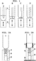
- FIG. 1 (A) a compensating element (3) is shown, on which a vessel (1) filled with a liquid is arranged.
- a pipette (2) was placed in the vessel to remove liquid.
- the pipette is located somewhat eccentrically to the vertex of the vessel bottom to prevent aspiration of the pipette tip.
- the compensation element simultaneously acts as a distance adjustment element.
- the level of liquid in the vessel drops and the weight force applied by the fluid to the clearance adjustment element decreases.
- the thereby becoming lighter vessel is lifted by the distance adjustment upwards.
- the vessel is lifted upwards (C) until the tip of the pipette touches the bottom of the vessel or is at least very close to it (D).
- the compensation element acts so that the pressure exerted by the pipette tip on the bottom of the vessel is compensated by the element in which the vessel dodges slightly downwards.
- the vessel (1) is applied directly to a spring or a resilient plastic as a compensation element (3), wherein the compensation element is arranged in a sleeve (6) on a fixing unit (8).
- this sleeve (6) is so long that the vessel by means of guide elements (7) guided safely and straight can be.
- the sleeve and the fastening unit on a bottom plate (9) is arranged.
- FIGS. 3A and 3B correspond to the structure of FIGS. 2A and 2B with the difference that the compensation element is seated directly on the bottom of the sleeve and the vessel is held by means of a holding device (4).
- FIGS. 4A and 4B the vessel is held by a holding device (4) which is connected to an active compensation element.
- the compensation element is controlled by a sensor with control unit (5).
- This element (5) measures in FIG. 4A the weight of the vessel and in FIG. 4B the height of the liquid level, where it simultaneously monitors the depth of immersion of the pipette tip, and deflects the distance adjustment according to a predetermined program.
- a program may consist of a simple formula that assigns a particular deflection to each weight or level of fluid.
- FIG. 5 a compensation element (3) is shown, to which a removal unit (pipette) is mounted so that pressure from below on the sampling tip is compensated by an evasive upward movement.
- a removal unit pipette
- a removal unit (2) is shown in the wall in a certain area, a compensation element (3) is integrated.
- a part of the wall is made elastic with a two-component injection molding process, or a part of the wall is designed as a bellows, as shown here.
- the negative pressure in the extraction unit is constant or at least uniform, the lower one becomes Part of the extraction unit by the increasingly liquid absorbed steadily heavier so that the tip can also be lowered automatically, so that compensating element acts as Abstandsverstellelement.
- FIG. 7 a vessel (1) is shown, the bottom of which is made of a foamed material which is sealed inwards, in order to ensure a sufficient tightness for liquids.
- This foamed material must be elastic enough to serve as a compensation element (3).
- Such vessels can be made, for example, with a two-component injection molding process. Advantage of such vessels is that they can be used in existing holders for disposable containers.
Landscapes
- Health & Medical Sciences (AREA)
- Chemical & Material Sciences (AREA)
- Clinical Laboratory Science (AREA)
- Chemical Kinetics & Catalysis (AREA)
- Analytical Chemistry (AREA)
- Life Sciences & Earth Sciences (AREA)
- Physics & Mathematics (AREA)
- Biochemistry (AREA)
- General Health & Medical Sciences (AREA)
- General Physics & Mathematics (AREA)
- Immunology (AREA)
- Pathology (AREA)
- Sampling And Sample Adjustment (AREA)
- Automatic Analysis And Handling Materials Therefor (AREA)
Description
- Die vorliegende Erfindung befasst sich mit einer Vorrichtung und einem Verfahren zur restlosen Aufnahme von Flüssigkeiten aus Gefäßen, insbesondere für die Entnahme von Reagenzien aus Reaktionsgefäßen durch Pipetten.
- Insbesondere bei Anwendungen im Bereich der Laboranalytik, werden häufig unterschiedliche Prozesse miteinander verknüpft. Dabei werden zur Aufnahme von Flüssigkeiten unter anderem spezielle Gefäße verwendet, wobei die Flüssigkeiten im Verlauf der Anwendung wieder entnommen werden.
- Aufgrund der fortschreitenden Automatisierung kommen verstärkt Robotersysteme (z.B. Liquid Handling Automaten) zum Einsatz, um beispielsweise ein Probenextrakt aus einem Gefäß eines ersten Prozesses in ein entsprechendes Behältnis für einen zweiten Prozesses zu überführen.
- Diese Systeme zum Flüssigkeitstransfer bestehen zumeist aus Entnahmeeinheiten (z.B. Pipetten), die von oben in die in der Regel aufrecht stehenden Gefäße eintauchen und die Flüssigkeit aus den Gefäßen heraus saugen.
- Die Entnahmeeinheiten weisen eine Entnahmespitze auf, die in die Flüssigkeit eingetaucht wird, um die Flüssigkeit zu entnehmen. Diese Spitze ist so geformt, dass ein Kanal, durch den die Flüssigkeit strömen kann, von einer Wandung umgeben ist. Der Kanal führt beginnend an der Entnahmespitze durch die Entnahmeeinheit hindurch.
Herrscht ein Unterdruck in dem Kanal wird die Flüssigkeit aus dem Gefäß herausgesaugt. Auf diese Weise wird die Flüssigkeit entnommen. - Die Entnahmespitze weist an ihrem Ende eine Endfläche auf, die von der begrenzenden Wandung definiert wird.
- Nachteil dieser bestehenden Systeme zum Flüssigkeitstransfer ist, dass die Flüssigkeit nicht restlos oder zumindest annähernd restlos aus den Gefäßen entnommen werden kann. Insbesondere geringe Flüssigkeitsmengen sind daher zurzeit nicht oder nur sehr schwer aus den Gefäßen zu entnehmen.
- Dies liegt darin begründet, dass immer ein gewisses Restvolumen im Gefäß verbleiben muss, da beim Versuch der quantitativen Überführung der Flüssigkeit die Gefahr besteht, dass durch eine zu tiefe Positionierung einer Entnahmeeinheit ein luft- oder flüssigkeitsdichter Abschluss zwischen der Entnahmespitze dieser Einheit und dem Gefäßboden entsteht. Beispielsweise darf eine Pipetierspitze in der Regel nicht den Boden des Gefäßes berühren, da beim Aufziehen der Flüssigkeit ein Unterdruck entsteht, der die Pipetierspitze an den Gefäßboden ansaugt und eine Flüssigkeitsaufnahme zunächst nicht erfolgen kann, da diese nicht in die Pipetierspitze eindringen kann.
Durch die anschließende Bewegung der Pipetierspitze nach oben bei bestehendem Unterdruck wird die Verbindung zum Gefäßboden gelöst und die Flüssigkeit schießt unkontrolliert in die Spitze. Dabei wird sie meist bis zum Filter eingesogen, was eine folgende kontrollierte Abgabe unmöglich macht. - Das bestehende Problem wird durch die Varianzen bezüglich Bemaßung und Form der Plastikmaterialien (Pipetierspitzen, Gefäße) noch verstärkt. Für hochsensitive Anwendungen im Bereich der PCR-basierten Analytik ist der automatisierte Transfer geringer Flüssigkeitsmengen quantitativ notwendig, da alle bisherigen Maßnahmen zu Sensitivitätsverlusten bzw. zum Totalverlust führen.
-
WO 2009/084451 A1 offenbart eine Vorrichtung zur Aufnahme von Flüssigkeiten aus Gefäßen mittels Entnahmeeinheiten. Die Ansaugöffnung zum Ansaugen der Flüssigkeiten ist auf einer seitlichen Umfangsfläche der Entnahmeeinheit angeordnet. -
JP 55 039029 A -
US 6 363 802 B1 offenbart eine Vorrichtung zum präzisen Absaugen kleiner Flüssigkeitsvolumina aus einem Probengefäß. Die Vorrichtung umfasst eine Saugsonde, deren Spitze in die abzusaugende Flüssigkeit eingetaucht wird. Die Saugsonde ist im Probengefäß mittig angeordnet. Die Spitze wird über einen Antriebsmechanismus in das Gefäß abgesenkt, bis die Spitze mit einer vorherbestimmbaren Kraft auf den Boden des Gefäßes auftrifft. -
US 6 270 726 B1 betrifft eine Pipettierstation mit einer Pipettiersonde und einer Abtasteinrichtung, die ein kontrolliertes Absenken der Pipettiersonde bis auf den Boden des Probengefäßes ermöglicht. Die Pipettiersonde ist im Probengefäß mittig angeordnet. - Der vorliegenden Erfindung lag die Aufgabe zugrunde, eine Vorrichtung und ein Verfahren zur Verfügung zu stellen, welche die oben aufgeführten Nachteile überwinden und zur restlosen Aufnahme von Flüssigkeiten aus Gefäßen geeignet sind.
- Die Aufgabe wird durch die Vorrichtung gemäß Anspruch 1 und das Verfahren gemäß Anspruch 8 gelöst.
- Danach betrifft die Erfindung eine Vorrichtung zur Aufnahme von Flüssigkeiten aus Gefäßen mittels Entnahmeeinheiten mit Entnahmespitzen, wobei die Vorrichtung Entnahmeeinheiten mit Entnahmespitzen sowie Gefäße für die zu entnehmende Flüssigkeit umfasst. Dabei sind die Entnahmespitzen so geformt, dass ein von einer Wandung umgebener, an der Entnahmespitze beginnender Kanal gebildet wird, wobei die Entnahmespitzen an ihrem Ende eine Endfläche aufweisen, die von der umgebenden Wandung definiert wird.
- Die erfindungsgemäße Vorrichtung ist dadurch gekennzeichnet, dass die Entnahmespitze oder der Gefäßboden so gestaltet oder relativ zueinander angeordnet ist/sind, dass der Flächenbereich des Gefäßbodens, auf dem bei Einführung der Entnahmespitze in das Gefäß die Entnahmespitze aufsetzen würde, und die Endfläche der Entnahmespitze zumindest auf einem Teilstück der beiden Flächenbereiche zueinander geneigt sind, dort also nicht parallel verlaufen; und wobei
- der Boden des Gefäßes gekrümmt ist und die Entnahmespitze exzentrisch zum Scheitelpunkt der Krümmung angeordnet ist; oder/und
- die Endfläche der Entnahmespitze die Form einer Krone aufweist oder Schlitze aufweist, die in die ansonsten plane Endfläche eingebracht sind.
- Auf diese Weise entsteht selbst beim Aufsetzen der Entnahmespitze auf dem Gefäßboden stets ein Spalt zwischen der entsprechenden Bodenfläche und der Endfläche der Entnahmespitze, so dass ein Festsaugen verhindert wird. Die Flüssigkeit kann in diesem Falle durch den Spalt in die Entnahmeeinheit fließen.
- Die erfindungsgemäße Vorrichtung ermöglicht die restlose Aufnahme von Flüssigkeiten aus einem Gefäß, in dem sich die zu entnehmende Flüssigkeit befindet.
- Die Erfindung umfasst die folgenden Anordnungen oder Formen, alleine oder auch in Kombination miteinander:
- der Boden des Gefäßes ist relativ zur planen Endfläche der Entnahmespitze schräg angeordnet,
- der Boden des Gefäßes ist gekrümmt, wobei die Entnahmespitze exzentrisch zum Scheitelpunkt der Krümmung angeordnet ist,
- die Endfläche der Entnahmespitze hat eine von der planen Fläche abweichende Form, nämlich indem sie die Form einer Krone hat oder indem Schlitze in die ansonsten plane Endfläche eingebracht sind.
- Ist das Gefäß am unteren Ende gewölbt, dann ist es zum Beispiel vorteilhaft, das Gefäß so unter der Entnahmeeinheit zu positionieren, dass die Spitze der Entnahmeeinheit ein wenig, d.h. 1/5 - 1/100 des Gefäßdurchmessers, von dem Scheitelpunkt der Wölbung entfernt den Boden des Gefäßes berühren würde.
- Eine bevorzugte Ausführungsform enthält zudem mindestens ein Kompensationselement, welches dazu geeignet ist, dass bei einer Berührung der Entnahmespitze mit dem Gefäßboden, beim Einführen der Entnahmespitze in das Gefäß, das Gefäß oder die Entnahmespitze in Richtung der relativen Bewegungsrichtung von Entnahmespitze und Gefäß ausweichen kann. Dies ist zum Beispiel der Fall, wenn das Gefäß und/oder die Entnahmespitze federnd gelagert sind.
- Bevorzugte Kompensationselemente sind aktive oder passive Elemente oder Kombinationen aus aktiven und passiven Elementen.
- Bevorzugte passive Elemente sind Federn oder andere federnde Materialien, wie z.B. federnde Kunststoffe wie Schaumstoffe oder Gummi. Als Federn können insbesondere Spiral- oder Blattfedern verwendet werden.
- der Boden des Gefäßes ist gekrümmt, wobei die Entnahmespitze exzentrisch zum Scheitelpunkt der Krümmung angeordnet ist,
- die Endfläche der Entnahmespitze ist relativ zur Längsachse der Entnahmespitze abgeschrägt oder hat eine andere von der planen Fläche abweichende Form, z.B. die Form einer Krone oder es sind Schlitze in die ansonsten plane Endfläche eingebracht.
- Ist das Gefäß am unteren Ende gewölbt, dann ist es zum Beispiel vorteilhaft, das Gefäß so unter der Entnahmeeinheit zu positionieren, dass die Spitze der Entnahmeeinheit ein wenig, d.h. 1/5 - 1/100 des Gefäßdurchmessers, von dem Scheitelpunkt der Wölbung entfernt den Boden des Gefäßes berühren würde.
- Eine bevorzugte Ausführungsform enthält zudem mindestens ein Kompensationselement, welches dazu geeignet ist, dass bei einer Berührung der Entnahmespitze mit dem Gefäßboden, beim Einführen der Entnahmespitze in das Gefäß, das Gefäß oder die Entnahmespitze in Richtung der relativen Bewegungsrichtung von Entnahmespitze und Gefäß ausweichen kann. Dies ist zum Beispiel der Fall, wenn das Gefäß und/oder die Entnahmespitze federnd gelagert sind.
- Bevorzugte Kompensationselemente sind aktive oder passive Elemente oder Kombinationen aus aktiven und passiven Elementen.
- Bevorzugte passive Elemente sind Federn oder andere federnde Materialien, wie z.B. federnde Kunststoffe wie Schaumstoffe oder Gummi. Als Federn können insbesondere Spiral- oder Blattfedern verwendet werden.
- Die passiven Elemente haben den Vorteil, dass eine Kompensation des Drucks auf den Gefäßboden und die Entnahmespitze einfach und ohne eine zusätzliche Regelung erfolgt.
Beim Aufsetzen der Entnahmespitze auf den Gefäßboden weicht dieser automatisch durch das elastische Kompensationselement nach unten aus oder die Entnahmespitze weicht nach oben aus. - Bevorzugte aktive Elemente sind Piezoelemente, Muskeldrähte oder Motoren die insbesondere jeweils mit Mechaniken versehen eine Kompensation des Drucks bei Berührung der Entnahmespitze mit dem Gefäßboden bewirken.
- In einer bevorzugten Ausführungsform werden diese aktiven Elemente durch einen Sensor, der den Anpressdruck misst, und einer Steuerelektronik versehen, die die Auslenkung des Kompensationselements steuert.
Eine aktive Regelung des Drucks zwischen Entnahmespitze und Gefäßboden hat den Vorteil, dass Fehler, z.B. Verkantungen, kompensiert werden können. - In einer bevorzugten Ausführungsform sind die Kompensationselemente aus handelsüblichen Federmaterial aufgebaut. Insbesondere besteht ein Kompensationselement aus elastischen Kunststoffen oder Federn.
- In einer bevorzugten Ausführungsform ist das Gefäß auf dem Kompensationselement vorzugsweise senkrecht oder leicht geneigt angeordnet, wobei es vorzugsweise durch eine auf dem Kompensationselement angebrachte Haltevorrichtung festgehalten wird.
Das Gefäß kann lösbar oder unlösbar mit dem Kompensationselement bzw. der Haltevorrichtung verbunden sein. Eine lösbare Verbindung hat den Vorteil, dass das Gefäß einfach austauschbar ist und z.B. Einweggefäße verwendet werden können.
Vorzugsweise ist das Gefäß nur auf das Kompensationselement bzw. die Haltevorrichtung aufgesetzt. - Vorzugsweise ist bei der ersten bevorzugten Ausführungsform das Kompensationselement auf einer Bodenplatte angebracht, um einen festen Stand des Elements zu gewährleisten.
- Bei einer weiteren bevorzugten Ausführungsform ist das Kompensationselement direkt in oder an der Entnahmeeinheit angeordnet, so dass die gesamte Entnahmeeinheit elastisch gelagert ist, oder ein Teil der Wandung der Entnahmeeinheit besteht aus einem elastischen Material oder ist als Balg ausgeführt, so dass zumindest die Entnahmespitze elastisch gelagert ist.
- Bei einer weiteren bevorzugten Ausführungsform sind Kompensationselemente sowohl an dem Gefäß als auch an der Entnahmeeinheit angeordnet.
- Um eine Verkippung zu vermeiden, ist das Kompensationselement bevorzugt in einer Führungseinheit angeordnet, z.B. einer Hülse mit zumindest einer Öffnung an der Oberseite. Diese Führungseinheit weist Führungselemente auf, die das Kompensationselement, die Haltevorrichtung, das Gefäß oder die Entnahmeeinheit auf einem geraden Wege führen. Bevorzugt bilden die Wände der oben genannten Hülse die Führungselemente.
Die Länge der Führungseinheit ist so beschaffen, dass sie das Kompensationselement, bevorzugt mit Haltevorrichtung, besonders bevorzugt auch zumindest einen Teil des Gefäßes oder der Entnahmeeinheit aufnehmen kann.
Die Führungseinheit ist vorzugsweise fest auf der Bodenplatte angebracht, insbesondere ist die Führungseinheit mittels eines Gewindes auf der Bodenplatte aufgeschraubt. - In einer weiteren bevorzugten Ausführungsform ist das Kompensationselement als ein Abstandsverstellelement ausgebildet, welches dazu geeignet ist, bei der Aufnahme einer Flüssigkeit aus dem Gefäß durch eine Entnahmeeinheit den relativen vertikalen Abstand zwischen Gefäßboden und Spitze der Entnahmeeinheit in Abhängigkeit der in dem Gefäß befindlichen Flüssigkeitsmenge so zu verändern, dass bei zunehmender Flüssigkeitsentnahme der Abstand zwischen Gefäßboden und Spitze der Entnahmeeinheit abnimmt.
Dabei sollte während der Entnahme die Spitze der Entnahmeeinheit stets unterhalb des Flüssigkeitsspiegels liegen, damit keine Luft eingesogen wird. - Bei einem flüssigkeitsgefüllten Gefäß in das eine Entnahmeeinheit eingebracht wird, läuft das Entnahmeverfahren in diesem Fall wie folgt ab:
- Im gefüllten Zustand des Gefäßes wird der Abstand zwischen Gefäßboden und Spitze der Entnahmeeinheit durch das Abstandsverstellelement maximal eingestellt.
- Die Entnahmeeinheit entnimmt dem Gefäß Flüssigkeit. Durch diese Flüssigkeitsentnahme wird, abhängig von der Flüssigkeitsmenge, die Entnahmeeinheit schwerer und das Gefäß leichter. Im übrigen steigt der Flüssigkeitsspiegel in der Entnahmeeinheit und sinkt im Gefäß ab.
- Bei fortlaufender Flüssigkeitsentnahme durch die Entnahmeeinheit wird dieser Abstand durch das Abstandsverstellelement in Abhängigkeit zur aufgenommenen Flüssigkeitsmenge stetig verringert. Dabei sollte die Spitze der Entnahmeeinheit stets unterhalb des Flüssigkeitsspiegels im Gefäß liegen.
Ein Maß für die entnommene Flüssigkeit kann zum einen die Gewichtskraft der aufgenommenen oder der im Gefäß verbliebenen Flüssigkeit sein oder der Flüssigkeitsspiegel in Gefäß oder Entnahmeeinheit.
Die Spitze der Entnahmeeinheit sollte den Gefäßboden nicht berühren, zumindest erst, wenn die Flüssigkeit nahezu komplett aufgesogen ist. - Bevorzugte Abstandsverstellelemente sind aktive oder passive Elemente oder Kombinationen aus aktiven und passiven Elementen.
- Geeignete passive Elemente regulieren den Abstand zwischen Gefäßboden und Spitze der Entnahmeeinheit vorzugsweise durch die Gewichtskraft der im Gefäß enthaltenen Flüssigkeitsmenge.
Bei passiven Abstandsverstellelementen geschieht eine Regulierung des Abstands zwischen Gefäßboden und Spitze der Entnahmeeinheit aufgrund der stets unterschiedlichen Gewichtskraft der transferierten Flüssigkeitsmenge automatisch, wenn das Abstandsverstellelement unter dem Gefäß oder an der Entnahmeeinheit angeordnet ist. Das Gefäß wird leichter und wird automatisch durch das elastische Abstandsverstellelement nach oben gedrückt, bzw. die Entnahmeeinheit wird schwerer und senkt sich automatisch ab. - Geeignete aktive Elemente regulieren den Abstand zwischen Gefäßboden und Spitze der Entnahmeeinheit vorzugsweise durch die Gewichtskraft der im Gefäß enthaltenen oder der durch die Entnahmeeinheit aufgenommenen Flüssigkeitsmenge oder deren Flüssigkeitsspiegel.
In einer bevorzugten Ausführungsform werden diese Elemente durch einen Sensor, der die Flüssigkeitsmenge misst und einer Steuerelektronik versehen, die die Auslenkung des Abstandsverstellelements steuert.
Eine aktive Abstandsverstellung hat den Vorteil, dass Fehler, z.B. Verkantungen, kompensiert werden können. Eine Messung der Höhe des Flüssigkeitsspiegels im Gefäß durch den Sensor hat den zusätzlichen Vorteil, dass gleichzeitig kontrolliert werden kann, ob die Spitze der Entnahmeeinheit bei der Entnahme auch stets unterhalb des Flüssigkeitsspiegels liegt. - Vorzugsweise sind passive Abstandsverstellelemente für inhomogen geformte (z.B. am Ende gewölbte) Gefäße so beschaffen, dass das Gefäß so angehoben wird, dass die Abstandsänderung bei abfallender Flüssigkeitsmenge pro entnommener Flüssigkeitseinheit stetig abnimmt.
Insbesondere bei einer gefederten Ausführungsform ist es vorteilhaft, am Ende schwächere Federkräfte wirken zu lassen. Dies wird mit einer Anordnung verschieden starker Federn oder einer Feder mit inhomogener Auslenkung pro Gewichtskraft erreicht. - Die Vorrichtung kann für ein oder mehrere Reaktionsgefäße oder Entnahmeeinheiten zur gleichzeitigen oder sukzessiven Entnahme vorgesehen sein. In einer vorteilhaften Ausführungsform ist jedes Probengefäß bzw. jede Entnahmeeinheit einzeln gelagert, um eventuelle Varianzen auszugleichen. Vorzugsweise ist die Vorrichtung für Reaktionsplatten im 12er, 24er oder 96-Format vorgesehen, indem diese Vorrichtungen in einer entsprechenden Anzahl rasterförmig angeordnet sind.
- Die Vorrichtung ist vorzugsweise so dimensioniert, dass sie mit handelsüblichen Automaten (Liquid Handlern) eingesetzt werden oder beim manuellen Arbeiten mit Pipetten eingesetzt werden kann.
- Vorzugsweise weist die Vorrichtung Kalibrationselemente auf, um den Abstand zwischen Entnahmeeinheit und Gefäßboden, vorzugsweise in einem klar definierten Zustand der Vorrichtung, zu kalibrieren.
- Bei einer bevorzugten Ausführungsform ist das Kompensationselement direkt im Gefäßboden integriert, insbesondere besteht der Gefäßboden aus einem federnden Material, z.B. ist der Gefäßboden geschäumt.
- Beispiele für die erfindungsgemäße Vorrichtung sind in den Abbildungen dargestellt.
-
Figur 1 zeigt in den Teilen A bis D schematisch den Aufbau der Vorrichtung und den Ablauf des Verfahrens. -
Figuren 2A und 2B zeigen Beispiele der Vorrichtung basierend auf Federn. -
Figuren 2A und 2B zeigen Beispiele der Vorrichtung mit Haltern basierend auf Federn. -
Figuren 4A und 4B zeigen Beispiele der Vorrichtung mit aktiven Kompensationselementen. -
Figur 5 zeigt ein Beispiel der Vorrichtung mit einem Kompensationselement an der Entnahmeeinheit. -
Figur 6 zeigt ein Beispiel der Vorrichtung mit einem in der Entnahmeeinheit integrierten Kompensationselement. -
Figur 7 zeigt ein Gefäß mit integriertem Kompensationselement. - In
Figur 1 (A) ist ein Kompensationselement (3) dargestellt, auf dem ein mit einer Flüssigkeit gefülltes Gefäß (1) angeordnet ist. Eine Pipette (2) wurde in das Gefäß eingebracht, um Flüssigkeit zu entnehmen.
In dem Beispiel ist die Pipette etwas exzentrisch zum Scheitelpunkt des Gefäßbodens angeordnet, um ein Ansaugen der Pipettenspitze zu verhindern. - In den Abbildungen 1B und 1C wirkt das Kompensationselement gleichzeitig als Abstandsverstellelement. Wird durch die Pipette Flüssigkeit aus dem Gefäß entnommen (B) sinkt der Flüssigkeitsspiegel in dem Gefäß und die durch die Flüssigkeit auf das Abstandsverstellelement ausgeübte Gewichtskraft. Das dadurch leichter werdende Gefäß wird durch das Abstandsverstellelement nach oben gehoben.
Das Gefäß wird so lange nach oben gehoben (C) bis die Spitze der Pipette auf dem Boden des Gefäßes aufsetzt oder sich zumindest sehr nahe über ihm befindet (D). - In
Figur 1D wirkt das Kompensationselement so, dass der Druck, den die Pipettenspitze bei der Berührung auf den Gefäßboden ausübt, durch das Element kompensiert wird, in dem das Gefäß etwas nach unten ausweicht. - In
Figur 2A ist das Gefäß (1) direkt auf eine Feder oder eine federnden Kunststoff als Kompensationselement (3) aufgebracht, wobei das Kompensationselement in einer Hülse (6) auf einer Befestigungseinheit (8) angeordnet ist.
InFigur 2B ist diese Hülse (6) so lang, dass das Gefäß mittels Führungselementen (7) sicher und gerade geführt werden kann. Zudem ist die Hülse und die Befestigungseinheit auf einer Bodenplatte (9) angeordnet. -
Figuren 3A und 3B entsprechen dem Aufbau derFiguren 2A und 2B mit dem Unterschied, dass das Kompensationselement direkt auf dem Boden der Hülse aufsitzt und das Gefäß mittels einer Haltevorrichtung (4) gehalten wird. - In
Figuren 4A und 4B wird das Gefäß durch eine Haltevorrichtung (4) gehalten, welche mit einem aktiven Kompensationselement verbunden ist. Das Kompensationselement wird durch einen Sensor mit Steuereinheit (5) gesteuert. Dieses Element (5) misst inFigur 4A die Gewichtskraft des Gefäßes und inFigur 4B die Höhe des Flüssigkeitsspiegels, wobei es dort gleichzeitig die Eintauchtiefe der Pipettenspitze überwacht, und lenkt das Abstandsverstellelement nach einem vorgegebenen Programm aus.
Ein solches Programm kann aus einer einfachen Formel bestehen, die jeder Gewichtskraft oder jeder Flüssigkeitsspiegelhöhe eine bestimmte Auslenkung zuweist. - In
Figur 5 ist ein Kompensationselement (3) dargestellt, an dem eine Entnahmeeinheit (Pipette) so befestigt ist, dass Druck von unten auf die Entnahmespitze durch eine Ausweichbewegung nach oben kompensiert wird. - In
Figur 6 ist eine Entnahmeeinheit (2) dargestellt, in deren Wand in einem bestimmten Bereich ein Kompensationselement (3) integriert ist. Dies kann dadurch realisiert werden, dass mit einem Zweikomponenten-Spritzgussverfahren ein Teil der Wand elastisch gestaltet wird, oder ein Teil der Wandung wie hier gezeigt als Balg ausgeführt ist.
In dem Fall, dass der Unterdruck in der Entnahmeeinheit konstant oder wenigstens gleichförmig ist, wird der untere Teil der Entnahmeeinheit durch die zunehmend aufgenommene Flüssigkeit stetig schwerer so dass die Spitze auch automatisch abgesenkt werden kann, dass Kompensationselement also als Abstandsverstellelement wirkt. - In
Figur 7 ist ein Gefäß (1) dargestellt, dessen Boden aus einem geschäumten Material beseht, das nach innen versiegelt ist, um eine Ausreichende Dichtigkeit für Flüssigkeiten zu gewährleisten. Dieses geschäumte Material muss dabei elastisch genug sein, um als Kompensationselement (3) dienen zu können. Solche Gefäße können z.B. mit einem Zweikomponenten-Spritzgussverfahren hergestellt werden.
Vorteil solcher Gefäße ist, dass sie in bereits vorhandene Halterungen für Einweggefäße eingesetzt werden können.
Claims (8)
- Vorrichtung zur Aufnahme von Flüssigkeiten aus Gefäßen mittels Entnahmeeinheiten mit Entnahmespitzen, wobei die Vorrichtung Entnahmeeinheiten (2) mit Entnahmespitzen sowie Gefäße (1) für die zu entnehmende Flüssigkeit umfasst, und wobei die Entnahmespitzen so geformt sind, dass ein von einer Wandung umgebener, an der Entnahmespitze beginnender Kanal gebildet wird, und wobei die Entnahmespitzen an ihrem Ende eine Endfläche aufweisen, die von der umgebenden Wandung definiert, wobei die Entnahmespitze oder der Gefäßboden so gestaltet oder relativ zueinander angeordnet ist/sind, dass der Flächenbereich des Gefäßbodens, auf dem bei Einführung der Entnahmespitze in das Gefäß die Entnahmespitze aufsetzen würde, und die Endfläche der Entnahmespitze zumindest auf einem Teilstück der beiden Flächenbereiche zueinander geneigt sind, dort also nicht parallel verlaufen; dadurch gekennzeichnet, dass:- der Boden des Gefäßes (1) gekrümmt ist und die Entnahmespitze exzentrisch zum Scheitelpunkt der Krümmung angeordnet ist; oder/und- die Endfläche der Entnahmespitze die Form einer Krone aufweist oder Schlitze aufweist, die in die ansonsten plane Endfläche eingebracht sind.
- Vorrichtung nach Anspruch 1, dadurch gekennzeichnet, dass die Vorrichtung mindestens ein Kompensationselement (3) enthält, welches dazu geeignet ist, dass bei einer Berührung der Entnahmespitze mit dem Gefäßboden das Gefäß oder die Entnahmespitze in Richtung der relativen Bewegungsrichtung von Entnahmespitze und Gefäß ausweichen kann.
- Vorrichtung nach Anspruch 1 oder 2, dadurch gekennzeichnet, dass das Kompensationselement (3) in einer Führungseinheit angeordnet ist, bevorzugt einer Hülse (6) mit zumindest einer Öffnung an der Oberseite, wobei die Führungseinheit vorzugsweise Führungselemente (7) aufweist, die das Kompensationselement, die Haltevorrichtung, das Gefäß (1) oder die Entnahmeeinheit (2) auf einem geraden Wege führen, wobei insbesondere die Wände der Hülse selbst die Führungselemente bilden.
- Vorrichtung nach einem der vorangehenden Ansprüche, dadurch gekennzeichnet, dass die Länge der Hülse so beschaffen ist, dass sie das Kompensationselement (3), bevorzugt mit Haltevorrichtung (4), besonders bevorzugt auch zumindest einen Teil des Gefäßes (1) oder der Entnahmeeinheit (2) aufnehmen kann.
- Vorrichtung nach einem der vorangehenden Ansprüche, dadurch gekennzeichnet, dass das Kompensationselement (3) Elemente aus der Gruppe aktive und passive Elemente enthält, vorzugsweise Elemente der Gruppe Federn, andere federnde Materialien, Piezo-elemente, Muskeldrähte und Motoren enthält.
- Vorrichtung nach einem der vorangehenden Ansprüche, dadurch gekennzeichnet, dass die Kompensationselemente (3) als Abstandsverstellelemente ausgestaltet sind.
- Vorrichtung nach einem der vorangehenden Ansprüche, dadurch gekennzeichnet, dass die Vorrichtung Kalibrationselemente aufweist auf, um den Abstand zwischen Gefäßboden und Spitze der Entnahmeeinheit zu kalibrieren.
- Verfahren zur restlosen Aufnahme von Flüssigkeiten aus flüssigkeitsgefüllten Gefäßen durch Entnahmeeinheiten mit Entnahmespitzen, dadurch gekennzeichnet, dass eine Vorrichtung gemäß Anspruch 1 verwendet wird, bei welcher der Boden des Gefäßes (1) gekrümmt ist und die Entnahmespitze exzentrisch zum Scheitelpunkt der Krümmung angeordnet ist, wobei das Gefäß so unter der Entnahmeeinheit (2) positioniert wird, dass die Spitze der Entnahmeeinheit 1/5 bis 1/100 des Gefäßdurchmessers von dem Scheitelpunkt der Wölbung entfernt den Boden des Gefäßes berühren würde.
Applications Claiming Priority (2)
| Application Number | Priority Date | Filing Date | Title |
|---|---|---|---|
| DE201010022552 DE102010022552B4 (de) | 2010-06-02 | 2010-06-02 | Vorrichtung und Verfahren zur restlosen Aufnahme von Flüssigkeiten aus Gefäßen |
| PCT/EP2011/002396 WO2011151014A1 (de) | 2010-06-02 | 2011-05-14 | Vorrichtung und verfahren zur restlosen aufnahme von flüssigkeiten aus gefässen |
Publications (2)
| Publication Number | Publication Date |
|---|---|
| EP2577321A1 EP2577321A1 (de) | 2013-04-10 |
| EP2577321B1 true EP2577321B1 (de) | 2017-04-19 |
Family
ID=44352337
Family Applications (1)
| Application Number | Title | Priority Date | Filing Date |
|---|---|---|---|
| EP11730897.3A Active EP2577321B1 (de) | 2010-06-02 | 2011-05-14 | Vorrichtung und verfahren zur restlosen aufnahme von flüssigkeiten aus gefässen |
Country Status (7)
| Country | Link |
|---|---|
| US (1) | US9108191B2 (de) |
| EP (1) | EP2577321B1 (de) |
| JP (1) | JP5956984B2 (de) |
| AU (1) | AU2011260626B2 (de) |
| CA (1) | CA2801217C (de) |
| DE (1) | DE102010022552B4 (de) |
| WO (1) | WO2011151014A1 (de) |
Families Citing this family (1)
| Publication number | Priority date | Publication date | Assignee | Title |
|---|---|---|---|---|
| DE102014004578B3 (de) * | 2014-03-28 | 2015-05-28 | Gerstel Systemtechnik Gmbh & Co. Kg | Vorrichtung zur automatischen Probenaufnahme |
Family Cites Families (43)
| Publication number | Priority date | Publication date | Assignee | Title |
|---|---|---|---|---|
| US2437697A (en) * | 1946-04-01 | 1948-03-16 | Kalom Lawrence | Electrical probe |
| US3991627A (en) * | 1975-11-28 | 1976-11-16 | Block Engineering, Inc. | Alignment device for sample containers |
| US4094641A (en) * | 1977-02-25 | 1978-06-13 | Waters Associates, Inc. | Low loss sample bottle assembly |
| JPS5539029A (en) | 1978-09-14 | 1980-03-18 | Hitachi Ltd | Suction mechanism for minute sample liquid |
| JPS59120960A (ja) * | 1982-12-28 | 1984-07-12 | Aloka Co Ltd | 吸引ノズルの自動插導方法 |
| JPS62265570A (ja) * | 1986-05-13 | 1987-11-18 | Fuji Photo Film Co Ltd | 自動点着装置 |
| AU585033B2 (en) * | 1986-07-04 | 1989-06-08 | Tosoh Corporation | Quantitative dispenser for a liquid |
| JP2611985B2 (ja) * | 1987-03-13 | 1997-05-21 | 株式会社日立製作所 | 試料精製方法及び装置 |
| US5132088A (en) * | 1988-11-17 | 1992-07-21 | Kabushiki Kaisha Nittec | Automatic medical sampling device |
| JPH08297125A (ja) * | 1995-04-26 | 1996-11-12 | Suzuki Motor Corp | 洗浄液吸引方法及びその装置 |
| SE9502183D0 (sv) | 1995-06-15 | 1995-06-15 | Pharmacia Ab | Säkerhetsanordning vid en pipettarm |
| EP2275821A1 (de) * | 1995-07-31 | 2011-01-19 | Precision System Science Co., Ltd | Behälter |
| US6117394A (en) * | 1996-04-10 | 2000-09-12 | Smith; James C. | Membrane filtered pipette tip |
| KR20010012479A (ko) * | 1997-05-02 | 2001-02-15 | 다니엘 엘. 캐시앙, 헨리 엘. 노르호프, 피터 알. 쉬어리 | 반응 리셉터클 장치 |
| CA2297175A1 (en) * | 1997-07-22 | 1999-02-04 | Jeffrey Van Ness | Polyethylenimine-based biomolecule arrays |
| DE19742163C2 (de) * | 1997-09-24 | 2001-12-13 | Steffen Hering | Vorrichtung und Verfahren zur Behandlung von Objekten in einem Flüssigkeitsbad |
| DE19756842A1 (de) * | 1997-10-29 | 1999-05-06 | Roche Diagnostics Gmbh | Verfahren und Vorrichtung zum Flüssigkeitstransfer mit einem Analysegerät |
| EP0913671A1 (de) | 1997-10-29 | 1999-05-06 | Roche Diagnostics GmbH | Verfahren und Vorrichtung zum Flüssigkeitstransfer mit einem Analysegerät |
| JP3869112B2 (ja) * | 1998-03-24 | 2007-01-17 | オリンパス株式会社 | 液体吸引方法 |
| EP0984285B1 (de) | 1998-08-31 | 2004-01-07 | Sysmex Corporation | Probenansauger mit zwei zusammenarbeitenden Handhabungseinheiten |
| GB2341804B (en) * | 1998-09-25 | 2003-02-12 | David William Parker | Improvements in or relating to hypodermic syringes |
| US6363802B1 (en) * | 1999-03-25 | 2002-04-02 | Coulter International Corp. | Apparatus for aspirating liquid from a vessel |
| CA2678141C (en) * | 1999-05-14 | 2011-09-06 | Gen-Probe Incorporated | Collection device comprising penetrable cap and method for use thereof |
| US6270726B1 (en) * | 1999-09-30 | 2001-08-07 | Dpc Cirrus, Inc. | Tube bottom sensing for small fluid samples |
| JP2002001092A (ja) * | 2000-06-22 | 2002-01-08 | Shimadzu Corp | 排液装置 |
| JP4613283B2 (ja) * | 2001-02-02 | 2011-01-12 | アークレイ株式会社 | 微量液の供給装置および混合装置 |
| US7335337B1 (en) * | 2001-09-11 | 2008-02-26 | Smith James C | Ergonomic pipette tip and adapters |
| JP2004325398A (ja) * | 2003-04-28 | 2004-11-18 | Hitachi Software Eng Co Ltd | 連続吸入用ニードル及び連続吸入装置 |
| JP4351875B2 (ja) | 2003-07-15 | 2009-10-28 | シスメックス株式会社 | 液体吸引装置とそれを備えた分析装置 |
| EP1749421A4 (de) * | 2004-03-05 | 2010-06-16 | Peter E Rising | Flüssigkeitsprobenentnahmevorrichtung und diese verwendendeerfahren |
| US7637175B1 (en) | 2004-08-26 | 2009-12-29 | Elemental Scientific, Inc. | Automated sampling device |
| US7284453B2 (en) | 2005-07-15 | 2007-10-23 | Beckman Coulter, Inc. | Method and apparatus for maximizing liquid aspiration from small vessels |
| EP1963854B1 (de) * | 2005-12-21 | 2021-02-03 | Meso Scale Technologies, LLC | Assay-vorrichtungen, -verfahren und -reagenzien |
| US7998708B2 (en) * | 2006-03-24 | 2011-08-16 | Handylab, Inc. | Microfluidic system for amplifying and detecting polynucleotides in parallel |
| DE102006020286A1 (de) * | 2006-04-27 | 2007-10-31 | Johannes-Gutenberg-Universität Mainz | Vorrichtung zur Entnahme von Flüssigkeiten |
| DE102007004856A1 (de) | 2007-01-31 | 2008-08-07 | Universität Wien | Pipetteneinrichtung, Manipulationseinrichtung und Verfahren zur Manipulation biologischer Zellen |
| EP2030683B1 (de) * | 2007-08-17 | 2013-10-02 | Qiagen GmbH | Vorrichtung und Verfahren zur Entnahme von Substanzen aus vorgefüllten Behältnissen |
| US8974750B2 (en) | 2007-12-27 | 2015-03-10 | Horiba, Ltd. | Nozzle device and liquid sample analyzer |
| US8202495B1 (en) * | 2008-06-23 | 2012-06-19 | Smith James C | Ergonomic pipette tip |
| DE102008058065A1 (de) * | 2008-11-18 | 2010-05-20 | Diasys Diagnostic Systems Gmbh | Automatisierte Analysevorrichtung mit einer automatischen Pipettiervorrichtung und mit einer Messvorrichtung zum Bestimmen der Position der Pipettiernadelspitze |
| JP2011058902A (ja) * | 2009-09-09 | 2011-03-24 | Aloka Co Ltd | ノズル装置および洗浄装置 |
| JP2011058897A (ja) * | 2009-09-09 | 2011-03-24 | Hitachi High-Technologies Corp | 自動分析装置 |
| US9242244B2 (en) * | 2010-02-09 | 2016-01-26 | Douglas T. Gjerde | Method and apparatus for pipette tip columns |
-
2010
- 2010-06-02 DE DE201010022552 patent/DE102010022552B4/de active Active
-
2011
- 2011-05-14 EP EP11730897.3A patent/EP2577321B1/de active Active
- 2011-05-14 WO PCT/EP2011/002396 patent/WO2011151014A1/de not_active Ceased
- 2011-05-14 US US13/701,216 patent/US9108191B2/en active Active
- 2011-05-14 AU AU2011260626A patent/AU2011260626B2/en active Active
- 2011-05-14 CA CA2801217A patent/CA2801217C/en active Active
- 2011-05-14 JP JP2013512778A patent/JP5956984B2/ja active Active
Non-Patent Citations (1)
| Title |
|---|
| None * |
Also Published As
| Publication number | Publication date |
|---|---|
| DE102010022552A1 (de) | 2011-12-08 |
| DE102010022552B4 (de) | 2013-06-27 |
| CA2801217C (en) | 2018-10-16 |
| AU2011260626B2 (en) | 2013-10-10 |
| CA2801217A1 (en) | 2011-12-08 |
| WO2011151014A1 (de) | 2011-12-08 |
| EP2577321A1 (de) | 2013-04-10 |
| US20130068042A1 (en) | 2013-03-21 |
| US9108191B2 (en) | 2015-08-18 |
| JP5956984B2 (ja) | 2016-07-27 |
| JP2013527460A (ja) | 2013-06-27 |
Similar Documents
| Publication | Publication Date | Title |
|---|---|---|
| DE60116441T2 (de) | Verfahren und Vorrichtung für die Abgabe von Flüssigkeiten | |
| EP3162443B1 (de) | Nadelführung mit zentrierung für septum-piercing | |
| DE2807262C2 (de) | Behälteranordnung mit einem restlos entleerbaren Probengefäß | |
| DE69825591T2 (de) | System und herstellungsverfahren für kleinvolumige übertragungselemente | |
| EP2927696B1 (de) | Vorrichtung zur automatischen probenaufnahme | |
| EP0478905B1 (de) | Vorrichtung zur Einführung von Pipettiereinsätzen durch Probegefäss-Stopfen | |
| EP2005196B1 (de) | Verfahren zum dosieren und mischen | |
| DE3220444A1 (de) | Pipetten-probenehmer | |
| EP2711080B1 (de) | Hohlnadel für einen probenpipettor | |
| WO2019228682A1 (de) | Pipettenspitze | |
| EP0331912A2 (de) | Befüllbares Probenaufnahmegefäss zur Handhabung einer flüssigen Probe | |
| EP2577321B1 (de) | Vorrichtung und verfahren zur restlosen aufnahme von flüssigkeiten aus gefässen | |
| WO2016092025A1 (de) | Spritzengehäuse zum pipettieren eines biologischen materials mit integrierten membranen | |
| EP3653304B1 (de) | Probenbehältnis | |
| DE10135963B4 (de) | Vorrichtung zum Pipettieren einer Flüssigkeit | |
| EP0187167A1 (de) | Dosiergerät für Flüssigkeiten | |
| EP0345527A2 (de) | Ansaughilfe zur Flüssigkeitsentnahme aus einem Gefäss | |
| EP1852704B1 (de) | Probeneingabevorrichtung | |
| EP3600673B1 (de) | Verfahren und dosiervorrichtung zum kontaktdosieren von flüssigkeiten | |
| EP1799349A1 (de) | Vorrichtung zum pipettieren | |
| DE19946783A1 (de) | Verfahren und Vorrichtung zur selektiven Pipettierung mit Multikanalpipetten | |
| DE112021007630T5 (de) | Septum | |
| DE69312839T2 (de) | Ansaugpipetten | |
| DE4230719A1 (de) | Vorrichtung zum Halten und zur Höheneinstellung von in Reihe angeordneten mit Analyseflüssigkeit gefüllten Behältern | |
| DE202025100341U1 (de) | Vorrichtung und Anlage zum Befüllen genesteter Behälter |
Legal Events
| Date | Code | Title | Description |
|---|---|---|---|
| PUAI | Public reference made under article 153(3) epc to a published international application that has entered the european phase |
Free format text: ORIGINAL CODE: 0009012 |
|
| 17P | Request for examination filed |
Effective date: 20121127 |
|
| AK | Designated contracting states |
Kind code of ref document: A1 Designated state(s): AL AT BE BG CH CY CZ DE DK EE ES FI FR GB GR HR HU IE IS IT LI LT LU LV MC MK MT NL NO PL PT RO RS SE SI SK SM TR |
|
| DAX | Request for extension of the european patent (deleted) | ||
| 17Q | First examination report despatched |
Effective date: 20150129 |
|
| GRAP | Despatch of communication of intention to grant a patent |
Free format text: ORIGINAL CODE: EPIDOSNIGR1 |
|
| INTG | Intention to grant announced |
Effective date: 20161129 |
|
| GRAS | Grant fee paid |
Free format text: ORIGINAL CODE: EPIDOSNIGR3 |
|
| GRAA | (expected) grant |
Free format text: ORIGINAL CODE: 0009210 |
|
| AK | Designated contracting states |
Kind code of ref document: B1 Designated state(s): AL AT BE BG CH CY CZ DE DK EE ES FI FR GB GR HR HU IE IS IT LI LT LU LV MC MK MT NL NO PL PT RO RS SE SI SK SM TR |
|
| REG | Reference to a national code |
Ref country code: GB Ref legal event code: FG4D Free format text: NOT ENGLISH |
|
| REG | Reference to a national code |
Ref country code: CH Ref legal event code: EP |
|
| REG | Reference to a national code |
Ref country code: AT Ref legal event code: REF Ref document number: 886467 Country of ref document: AT Kind code of ref document: T Effective date: 20170515 |
|
| REG | Reference to a national code |
Ref country code: IE Ref legal event code: FG4D Free format text: LANGUAGE OF EP DOCUMENT: GERMAN |
|
| REG | Reference to a national code |
Ref country code: DE Ref legal event code: R096 Ref document number: 502011012078 Country of ref document: DE |
|
| REG | Reference to a national code |
Ref country code: NL Ref legal event code: MP Effective date: 20170419 |
|
| REG | Reference to a national code |
Ref country code: LT Ref legal event code: MG4D |
|
| PG25 | Lapsed in a contracting state [announced via postgrant information from national office to epo] |
Ref country code: NL Free format text: LAPSE BECAUSE OF FAILURE TO SUBMIT A TRANSLATION OF THE DESCRIPTION OR TO PAY THE FEE WITHIN THE PRESCRIBED TIME-LIMIT Effective date: 20170419 |
|
| PG25 | Lapsed in a contracting state [announced via postgrant information from national office to epo] |
Ref country code: ES Free format text: LAPSE BECAUSE OF FAILURE TO SUBMIT A TRANSLATION OF THE DESCRIPTION OR TO PAY THE FEE WITHIN THE PRESCRIBED TIME-LIMIT Effective date: 20170419 Ref country code: HR Free format text: LAPSE BECAUSE OF FAILURE TO SUBMIT A TRANSLATION OF THE DESCRIPTION OR TO PAY THE FEE WITHIN THE PRESCRIBED TIME-LIMIT Effective date: 20170419 Ref country code: FI Free format text: LAPSE BECAUSE OF FAILURE TO SUBMIT A TRANSLATION OF THE DESCRIPTION OR TO PAY THE FEE WITHIN THE PRESCRIBED TIME-LIMIT Effective date: 20170419 Ref country code: NO Free format text: LAPSE BECAUSE OF FAILURE TO SUBMIT A TRANSLATION OF THE DESCRIPTION OR TO PAY THE FEE WITHIN THE PRESCRIBED TIME-LIMIT Effective date: 20170719 Ref country code: LT Free format text: LAPSE BECAUSE OF FAILURE TO SUBMIT A TRANSLATION OF THE DESCRIPTION OR TO PAY THE FEE WITHIN THE PRESCRIBED TIME-LIMIT Effective date: 20170419 Ref country code: GR Free format text: LAPSE BECAUSE OF FAILURE TO SUBMIT A TRANSLATION OF THE DESCRIPTION OR TO PAY THE FEE WITHIN THE PRESCRIBED TIME-LIMIT Effective date: 20170720 |
|
| PG25 | Lapsed in a contracting state [announced via postgrant information from national office to epo] |
Ref country code: BG Free format text: LAPSE BECAUSE OF FAILURE TO SUBMIT A TRANSLATION OF THE DESCRIPTION OR TO PAY THE FEE WITHIN THE PRESCRIBED TIME-LIMIT Effective date: 20170719 Ref country code: IS Free format text: LAPSE BECAUSE OF FAILURE TO SUBMIT A TRANSLATION OF THE DESCRIPTION OR TO PAY THE FEE WITHIN THE PRESCRIBED TIME-LIMIT Effective date: 20170819 Ref country code: PL Free format text: LAPSE BECAUSE OF FAILURE TO SUBMIT A TRANSLATION OF THE DESCRIPTION OR TO PAY THE FEE WITHIN THE PRESCRIBED TIME-LIMIT Effective date: 20170419 Ref country code: SE Free format text: LAPSE BECAUSE OF FAILURE TO SUBMIT A TRANSLATION OF THE DESCRIPTION OR TO PAY THE FEE WITHIN THE PRESCRIBED TIME-LIMIT Effective date: 20170419 Ref country code: LV Free format text: LAPSE BECAUSE OF FAILURE TO SUBMIT A TRANSLATION OF THE DESCRIPTION OR TO PAY THE FEE WITHIN THE PRESCRIBED TIME-LIMIT Effective date: 20170419 Ref country code: RS Free format text: LAPSE BECAUSE OF FAILURE TO SUBMIT A TRANSLATION OF THE DESCRIPTION OR TO PAY THE FEE WITHIN THE PRESCRIBED TIME-LIMIT Effective date: 20170419 |
|
| REG | Reference to a national code |
Ref country code: DE Ref legal event code: R097 Ref document number: 502011012078 Country of ref document: DE |
|
| PG25 | Lapsed in a contracting state [announced via postgrant information from national office to epo] |
Ref country code: EE Free format text: LAPSE BECAUSE OF FAILURE TO SUBMIT A TRANSLATION OF THE DESCRIPTION OR TO PAY THE FEE WITHIN THE PRESCRIBED TIME-LIMIT Effective date: 20170419 Ref country code: MC Free format text: LAPSE BECAUSE OF FAILURE TO SUBMIT A TRANSLATION OF THE DESCRIPTION OR TO PAY THE FEE WITHIN THE PRESCRIBED TIME-LIMIT Effective date: 20170419 Ref country code: RO Free format text: LAPSE BECAUSE OF FAILURE TO SUBMIT A TRANSLATION OF THE DESCRIPTION OR TO PAY THE FEE WITHIN THE PRESCRIBED TIME-LIMIT Effective date: 20170419 Ref country code: DK Free format text: LAPSE BECAUSE OF FAILURE TO SUBMIT A TRANSLATION OF THE DESCRIPTION OR TO PAY THE FEE WITHIN THE PRESCRIBED TIME-LIMIT Effective date: 20170419 Ref country code: CZ Free format text: LAPSE BECAUSE OF FAILURE TO SUBMIT A TRANSLATION OF THE DESCRIPTION OR TO PAY THE FEE WITHIN THE PRESCRIBED TIME-LIMIT Effective date: 20170419 Ref country code: SK Free format text: LAPSE BECAUSE OF FAILURE TO SUBMIT A TRANSLATION OF THE DESCRIPTION OR TO PAY THE FEE WITHIN THE PRESCRIBED TIME-LIMIT Effective date: 20170419 |
|
| REG | Reference to a national code |
Ref country code: IE Ref legal event code: MM4A |
|
| PLBE | No opposition filed within time limit |
Free format text: ORIGINAL CODE: 0009261 |
|
| STAA | Information on the status of an ep patent application or granted ep patent |
Free format text: STATUS: NO OPPOSITION FILED WITHIN TIME LIMIT |
|
| PG25 | Lapsed in a contracting state [announced via postgrant information from national office to epo] |
Ref country code: SM Free format text: LAPSE BECAUSE OF FAILURE TO SUBMIT A TRANSLATION OF THE DESCRIPTION OR TO PAY THE FEE WITHIN THE PRESCRIBED TIME-LIMIT Effective date: 20170419 Ref country code: IT Free format text: LAPSE BECAUSE OF FAILURE TO SUBMIT A TRANSLATION OF THE DESCRIPTION OR TO PAY THE FEE WITHIN THE PRESCRIBED TIME-LIMIT Effective date: 20170419 |
|
| REG | Reference to a national code |
Ref country code: FR Ref legal event code: ST Effective date: 20180131 |
|
| 26N | No opposition filed |
Effective date: 20180122 |
|
| PG25 | Lapsed in a contracting state [announced via postgrant information from national office to epo] |
Ref country code: LU Free format text: LAPSE BECAUSE OF NON-PAYMENT OF DUE FEES Effective date: 20170514 |
|
| REG | Reference to a national code |
Ref country code: BE Ref legal event code: MM Effective date: 20170531 |
|
| PG25 | Lapsed in a contracting state [announced via postgrant information from national office to epo] |
Ref country code: IE Free format text: LAPSE BECAUSE OF NON-PAYMENT OF DUE FEES Effective date: 20170514 |
|
| PG25 | Lapsed in a contracting state [announced via postgrant information from national office to epo] |
Ref country code: SI Free format text: LAPSE BECAUSE OF FAILURE TO SUBMIT A TRANSLATION OF THE DESCRIPTION OR TO PAY THE FEE WITHIN THE PRESCRIBED TIME-LIMIT Effective date: 20170419 Ref country code: FR Free format text: LAPSE BECAUSE OF NON-PAYMENT OF DUE FEES Effective date: 20170619 |
|
| REG | Reference to a national code |
Ref country code: AT Ref legal event code: MM01 Ref document number: 886467 Country of ref document: AT Kind code of ref document: T Effective date: 20170514 |
|
| PG25 | Lapsed in a contracting state [announced via postgrant information from national office to epo] |
Ref country code: AT Free format text: LAPSE BECAUSE OF NON-PAYMENT OF DUE FEES Effective date: 20170514 Ref country code: BE Free format text: LAPSE BECAUSE OF NON-PAYMENT OF DUE FEES Effective date: 20170531 |
|
| PG25 | Lapsed in a contracting state [announced via postgrant information from national office to epo] |
Ref country code: MT Free format text: LAPSE BECAUSE OF FAILURE TO SUBMIT A TRANSLATION OF THE DESCRIPTION OR TO PAY THE FEE WITHIN THE PRESCRIBED TIME-LIMIT Effective date: 20170419 |
|
| PG25 | Lapsed in a contracting state [announced via postgrant information from national office to epo] |
Ref country code: HU Free format text: LAPSE BECAUSE OF FAILURE TO SUBMIT A TRANSLATION OF THE DESCRIPTION OR TO PAY THE FEE WITHIN THE PRESCRIBED TIME-LIMIT; INVALID AB INITIO Effective date: 20110514 |
|
| PG25 | Lapsed in a contracting state [announced via postgrant information from national office to epo] |
Ref country code: CY Free format text: LAPSE BECAUSE OF NON-PAYMENT OF DUE FEES Effective date: 20170419 |
|
| PG25 | Lapsed in a contracting state [announced via postgrant information from national office to epo] |
Ref country code: MK Free format text: LAPSE BECAUSE OF FAILURE TO SUBMIT A TRANSLATION OF THE DESCRIPTION OR TO PAY THE FEE WITHIN THE PRESCRIBED TIME-LIMIT Effective date: 20170419 |
|
| PG25 | Lapsed in a contracting state [announced via postgrant information from national office to epo] |
Ref country code: TR Free format text: LAPSE BECAUSE OF FAILURE TO SUBMIT A TRANSLATION OF THE DESCRIPTION OR TO PAY THE FEE WITHIN THE PRESCRIBED TIME-LIMIT Effective date: 20170419 |
|
| PG25 | Lapsed in a contracting state [announced via postgrant information from national office to epo] |
Ref country code: PT Free format text: LAPSE BECAUSE OF FAILURE TO SUBMIT A TRANSLATION OF THE DESCRIPTION OR TO PAY THE FEE WITHIN THE PRESCRIBED TIME-LIMIT Effective date: 20170419 |
|
| PG25 | Lapsed in a contracting state [announced via postgrant information from national office to epo] |
Ref country code: AL Free format text: LAPSE BECAUSE OF FAILURE TO SUBMIT A TRANSLATION OF THE DESCRIPTION OR TO PAY THE FEE WITHIN THE PRESCRIBED TIME-LIMIT Effective date: 20170419 |
|
| P01 | Opt-out of the competence of the unified patent court (upc) registered |
Effective date: 20230425 |
|
| PGFP | Annual fee paid to national office [announced via postgrant information from national office to epo] |
Ref country code: DE Payment date: 20250529 Year of fee payment: 15 |
|
| PGFP | Annual fee paid to national office [announced via postgrant information from national office to epo] |
Ref country code: GB Payment date: 20250527 Year of fee payment: 15 |
|
| PGFP | Annual fee paid to national office [announced via postgrant information from national office to epo] |
Ref country code: CH Payment date: 20250601 Year of fee payment: 15 |