EP2578054B1 - Résistance blindée avec une terminaison étanche - Google Patents
Résistance blindée avec une terminaison étanche Download PDFInfo
- Publication number
- EP2578054B1 EP2578054B1 EP11728790.4A EP11728790A EP2578054B1 EP 2578054 B1 EP2578054 B1 EP 2578054B1 EP 11728790 A EP11728790 A EP 11728790A EP 2578054 B1 EP2578054 B1 EP 2578054B1
- Authority
- EP
- European Patent Office
- Prior art keywords
- armour
- electric pin
- annular element
- resistor according
- bushing
- Prior art date
- Legal status (The legal status is an assumption and is not a legal conclusion. Google has not performed a legal analysis and makes no representation as to the accuracy of the status listed.)
- Active
Links
Images


Classifications
-
- H—ELECTRICITY
- H01—ELECTRIC ELEMENTS
- H01H—ELECTRIC SWITCHES; RELAYS; SELECTORS; EMERGENCY PROTECTIVE DEVICES
- H01H37/00—Thermally-actuated switches
- H01H37/74—Switches in which only the opening movement or only the closing movement of a contact is effected by heating or cooling
- H01H37/76—Contact member actuated by melting of fusible material, actuated due to burning of combustible material or due to explosion of explosive material
- H01H37/761—Contact member actuated by melting of fusible material, actuated due to burning of combustible material or due to explosion of explosive material with a fusible element forming part of the switched circuit
-
- H—ELECTRICITY
- H01—ELECTRIC ELEMENTS
- H01C—RESISTORS
- H01C17/00—Apparatus or processes specially adapted for manufacturing resistors
- H01C17/02—Apparatus or processes specially adapted for manufacturing resistors adapted for manufacturing resistors with envelope or housing
-
- H—ELECTRICITY
- H05—ELECTRIC TECHNIQUES NOT OTHERWISE PROVIDED FOR
- H05B—ELECTRIC HEATING; ELECTRIC LIGHT SOURCES NOT OTHERWISE PROVIDED FOR; CIRCUIT ARRANGEMENTS FOR ELECTRIC LIGHT SOURCES, IN GENERAL
- H05B3/00—Ohmic-resistance heating
- H05B3/02—Details
- H05B3/04—Waterproof or air-tight seals for heaters
-
- H—ELECTRICITY
- H05—ELECTRIC TECHNIQUES NOT OTHERWISE PROVIDED FOR
- H05B—ELECTRIC HEATING; ELECTRIC LIGHT SOURCES NOT OTHERWISE PROVIDED FOR; CIRCUIT ARRANGEMENTS FOR ELECTRIC LIGHT SOURCES, IN GENERAL
- H05B3/00—Ohmic-resistance heating
- H05B3/02—Details
- H05B3/06—Heater elements structurally combined with coupling elements or holders
-
- H—ELECTRICITY
- H05—ELECTRIC TECHNIQUES NOT OTHERWISE PROVIDED FOR
- H05B—ELECTRIC HEATING; ELECTRIC LIGHT SOURCES NOT OTHERWISE PROVIDED FOR; CIRCUIT ARRANGEMENTS FOR ELECTRIC LIGHT SOURCES, IN GENERAL
- H05B3/00—Ohmic-resistance heating
- H05B3/40—Heating elements having the shape of rods or tubes
- H05B3/42—Heating elements having the shape of rods or tubes non-flexible
-
- Y—GENERAL TAGGING OF NEW TECHNOLOGICAL DEVELOPMENTS; GENERAL TAGGING OF CROSS-SECTIONAL TECHNOLOGIES SPANNING OVER SEVERAL SECTIONS OF THE IPC; TECHNICAL SUBJECTS COVERED BY FORMER USPC CROSS-REFERENCE ART COLLECTIONS [XRACs] AND DIGESTS
- Y10—TECHNICAL SUBJECTS COVERED BY FORMER USPC
- Y10T—TECHNICAL SUBJECTS COVERED BY FORMER US CLASSIFICATION
- Y10T29/00—Metal working
- Y10T29/49—Method of mechanical manufacture
- Y10T29/49002—Electrical device making
- Y10T29/49082—Resistor making
- Y10T29/49087—Resistor making with envelope or housing
Definitions
- the present invention relates to an armoured resistor with an end sealing element.
- Armoured resistors are used in household appliances that come in contact with water, such as washing machines, dishwashers and the like.
- armoured resistors can incorporate safety devices which, if the equipment or any component thereof malfunctions, eliminate the risk of fire thereof.
- thermal fuses can be incorporated, capable of cutting off the power supply to the resistor when it exceeds a predetermined temperature.
- resistors are formed by a resistance wire inserted coaxially in tube-shaped metal armour and filled with powder of an electrical insulator, for example magnesium oxide.
- each end of the tube-shaped armour there is a projecting metal electric pin, suitably isolated electrically from the tube-shaped armour, both caps being intended to be connected to a power supply.
- a thermal fuse can be present at one or both of said ends.
- the thermal fuse is connected electrically and mechanically by a first conducting wire to said electric pin, in the portion inside said tube-shaped armour, and is connected electrically and mechanically by a second conducting wire to a metallic element, to which, said resistance wire is connected.
- seals are provided between the electric pin and the armour. These seals have the following functions:
- the seal is generally made with resins, for example epoxy or polyurethane resins.
- the prior art proposes the use of silicone insulating material with characteristics of water repellence and of beads of plastic or ceramic for mechanical fixing of the electric pin to the armour.
- the bead is only required to have a function of sealing with respect to the insulating powder, so that it does not escape from the resistor, whereas it is no longer also necessary for it to have characteristics of sealing against moisture.
- thermal fuse makes it essential to ensure perfect stability for the electric pin relative to the armour. In fact, in resistors without the thermal fuse the electric pin is blocked by the magnesium oxide. In resistors in which at least one electric pin is connected electrically to a thermal fuse, the electric pin cannot be blocked in the magnesium oxide owing to the presence of the thermal fuse.
- Patent US7496284 describes a method of thermally deforming a bead, so that it seals the end of the resistor. According to another variant described, it is envisaged that the end of the armour is deformed around the bead. In accordance with that document, tests demonstrated insufficient stability of the electric pin, with consequent damage of the thermal fuse.
- Patent DE19535389 shows a circumferential groove made in the electric pin for the purpose of improving adhesion between the electric pin and the bead in order to improve the moisture-proofness of an armoured resistor. This solution does not, however, solve the problem of strengthening the adhesion between electric pin and bead for the purposes of improving the mechanical strength of the assembly.
- Patent DE 9410403 and patent application JP2003068433 show other relevant prior art solutions, which however do not the purpose of the present invention.
- the purpose of the present invention is to provide an armoured resistor with an end sealing bead that is able to solve the aforementioned problem.
- the present invention relates to an armoured resistor with two caps, of domestic appliances, comprising:
- teeth are always much more effective than knurling, as teeth offer better interpenetration of the annular element and the teeth of the electric pin, ensuring better axial resistance of the latter. This is essentially because the fluorinated materials used are significantly rigid.
- said portion of peripheral surface comprises at least one peripheral circular groove.
- the end of armour is deformed so that said annular element interpenetrates with said peripheral surface.
- the peripheral surface comprises only toothing with parallel extension relative to said axis of longitudinal extension.
- the grooves/protuberances defined by the teeth solve the problem of ensuring torsional stability for the electric pin/bead assembly, much better than knurling.
- said portion of peripheral surface comprises at least one peripheral circular groove.
- the end of armour is deformed so that said annular element interpenetrates with said peripheral surface.
- the peripheral surface comprises only toothing with parallel extension relative to said axis of longitudinal extension.
- the annular element is a sealing bead, preferably made of plastic material or fluorinated material (PTFE-PFA).
- the resistor comprises a bushing with axial symmetry encircling the thermal fuse inside the armour. More preferably, the bushing and the sealing bead are contiguous with respect to said axis of longitudinal extension. Even more preferably, corresponding to a thermal fuse, an electrically insulating bushing is present, and the bushing and the sealing bead are contiguous, and a sealing gasket, preferably an O-ring, is interposed between them.
- a sealing gasket preferably an O-ring
- the annular element is a bushing made of plastic material or fluorinated material (PTFE-PFA) encircling the thermal fuse inside the armour and in which said sealing element is made of silicone material.
- PTFE-PFA fluorinated material
- Another objective of the present invention is to provide a method of assembly of an armoured resistor with a sealing bead able to solve the aforementioned problem.
- the present invention also relates to a method of assembly of an armoured resistor according to the present invention.
- the method comprises the following successive steps:
- the annular element is a sealing bead and the method further comprises the preliminary steps of providing a further bushing for encircling the thermal fuse inside the armour and of interposing an annular gasket between said bushing and said sealing bead.
- the resistance of the armoured resistor to moisture and to the intrusion of foreign bodies is improved.
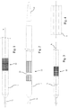
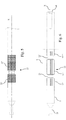
- an example of application of the present invention comprises armour 1, preferably tube-shaped, i.e. with axial extension, which houses within it a metal electric pin 2 partially projecting relative to an end 1' of the armour 1, a thermal fuse 3, connected by a first conducting wire to said electric pin 2 and by a second conducting wire to an internal metallic element 4 which can be connected to a resistance wire, not shown in this figure.
- the metal electric pin 2 has globally cylindrical symmetry defining a longitudinal extension X, generally coinciding with the axial extension of the armour, and comprises a first tapered part 21 of electrical and mechanical interconnection with a respective external electrical connector (not shown).
- the metal electric pin 2 is held in position relative to the armour by a sealing element 5, commonly called a bead.
- a second cylindrical part 22 has high roughness for the purpose of providing a high coefficient of friction corresponding to the contact zone with the sealing bead 5. This can therefore be interposed between the electric pin 2 and the end 1' of armour 1, in order to hold the metal electric pin in position and in order to seal the inside of the armour.
- a preferred sealing bead 5 has cylindrical shape, hollow internally, and more generally has axial symmetry with an external surface compatible with the shape of the armour and an internal through-cavity, compatible with the shape of the electric pin.
- said second part 22, in contact with the bead comprises at least one longitudinal surface protuberance and/or a one longitudinal groove, for example knurling continuous at least in parts, in order to ensure static adhesion between electric pin and sealing bead capable of resisting torsional stresses. In other words, even if a torque is applied to the electric pin, the latter does not turn relative to the bead 5.
- said second part 22 comprises a first portion 22' knurled at a first angle and a second part 22' knurled at a second angle different from the first.
- the electric pin still has a globally symmetric shape and in particular cylindrical relative to the longitudinal extension X, locally it is asymmetric through the presence of the teeth of the knurling.
- the second part comprises teeth with a longitudinal extension, i.e. coinciding with the longitudinal extension of the electric pin 2.
- the electric pin comprises both a knurled/toothed zone etc., and at least one circular groove 23, the latter can be both internal and external to said knurled zone, see for example Figs. 2 and 3 .
- electric pin 2 comprises two circular grooves 23 and 23', which demarcate three separate portions 22', 22" and 22'" of longitudinal knurling or toothing.
- said knurling or toothing 22', 22", 22"' enables the armoured resistor to withstand a torque applied to the electric pin of the order of 100 Ncm or more.
- said circular grooves 23, 23', etc. do not have any component parallel to the axial extension of the electric pin, but improve the adhesion of electric pin to the bead 5 for the purpose of resisting axial stresses, for example during connection or disconnection of the tapered end 21 in a suitable external electrical connector.
- a sealing bead 5 made of plastic or fluorinated materials, a tube-shaped metal armour 1, a method of assembly of the armoured resistor envisages the following steps:
- Said positioning is such that said sealing bead 5 also covers at least one groove 23, when present.
- the method can comprise a preliminary step of juxtaposition of electric pin 2 with the associated resistance wire in armour 1 and a further step of filling the armour with powder of insulating material, such as magnesium oxide, optionally mixed or treated with silicone resins.
- insulating material such as magnesium oxide, optionally mixed or treated with silicone resins.
- said sealing bead 5 prefferably be of plastic material, or PTFE, PFA so that it deforms suitably to adhere to said roughness.
- the electric pin 2, the sealing bead 5 and the end 1' of the armour 1 become one, also owing to the synergistic effect of the conformation of said electric pin 2 and of the permanent deformations induced in end 1' of the armour, which in their turn cause the sealing bead 5 to deform.
- Said assemblage enables the armoured resistor to withstand a force of compression and/or tension applied to each electric pin equal to 100N or more, without the electric pin moving axially relative to the armour.
- said armour 1 can comprise, according to the axial section in Fig. 7 , a stop tooth 11, defining the portion of the sealing bead 5 intended to be inside the armour, to facilitate the operation of positioning of the bead 5.
- magnesium oxide used for filling the armour and isolating electrically the resistance wire passing through it internally, to be mixed with silicone material with characteristics of water repellence.
- the present invention offers the possibility of beneficial use of sealing elements 5 made of plastic or fluorinated material.
- bushing 7 in addition to the sealing bead 5, there is a so-called bushing 7, generally made of plastic material.
- This bushing generally has the purpose of keeping the thermal fuse coaxial with the armour. This does not rule out other possible purposes.
- the sealing bead and the bushing are dimensioned so that they are axially contiguous inside the armour.
- annular gasket 8 preferably an O-ring, is interposed between the sealing bead 5 and the bushing 7.
- This gasket interacting with the sealing bead 5, the bushing 7 and the armour 1, guarantees perfect sealing of the interior of the armour, preventing the ingress of moisture that would impair the characteristics of electrical insulation of said armoured resistor.
- Fig. 8 shows the resistor during a preferred method of manufacture in which bushing 7 is inserted in the armour.
- Fig. 9 shows the resistor after:
- Rolling envisages a radial reduction of the armour, which thus becomes narrower, locking inside it both the bushing 7, which in Fig. 9 is shown deformed, and the sealing bead 5: the latter locking between them the O-ring in peripherally external contact with the armour.
- the O-ring it is preferable for the O-ring to have dimensions such that it is in contact externally with the armour and internally with the electric pin 2.
- This effect can advantageously be amplified by compressing the O-ring between the bushing and the bead.
- the rolling process envisages working the armour by means of rolls, which gradually reduce the radial dimensions, according to a transverse section, of the armour, uniformly in the radial and longitudinal direction.
- Coining is a process that reduces the radial dimensions of the armour locally.
- Pressing is a process that involves a portion of the armour, producing a uniform or non-uniform reduction of its radial dimensions on a fairly extensive region of the armour, but not on the whole armour.
- the knurled/toothed part 22', 22", etc., of electric pin 2 is in contact with the bushing 7, so that the latter has to perform a mechanical function of connection of the electric pin 2 to the armour 1, applying to this everything said previously in relation to the sealing bead 5, for example in relation to coining or rolling of the armour.
- the bushing is internal, it is not necessary for it to have particular characteristics of hermeticity against moisture and foreign bodies, and it can, advantageously, be made of poor material.
- the sealing bead 5 performs the sole task of sealing the armour and no longer of holding the electric pin, so that, rather than being made of expensive Teflon, it can be made of more economical silicone material.
Landscapes
- Engineering & Computer Science (AREA)
- Manufacturing & Machinery (AREA)
- Microelectronics & Electronic Packaging (AREA)
- Chemical & Material Sciences (AREA)
- Combustion & Propulsion (AREA)
- Details Of Resistors (AREA)
- Connector Housings Or Holding Contact Members (AREA)
- Resistance Heating (AREA)
- Fuses (AREA)
Claims (12)
- Résistance blindée à deux bouchons, pour appareils ménagers, comprenant :- un blindage (1) présentant deux extrémités opposées, l'une desdites extrémités définissant un axe d'extension longitudinale (X),- un connecteur électrique à broche (2) faisant partiellement saillie depuis l'une desdites extrémités (1') et relié à ladite extrémité (1') par un élément annulaire (5, 7) à symétrie axiale, comprenant une cavité traversante dans laquelle s'engage ledit connecteur électrique à broche (2), de sorte que le connecteur électrique à broche est coaxial audit axe d'extension longitudinale (X),- un fusible thermique (3) disposé à l'intérieur dudit blindage (1) et connecté électriquement audit connecteur électrique à broche (2),le connecteur électrique à broche (2) présente une partie de la surface périphérique (22) en contact avec la cavité traversante dudit élément annulaire (5, 7),
caractérisée en ce que ladite partie de la surface périphérique (22) comprend un moletage ou une denture définissant au moins un composant d'extension parallèle audit axe d'extension longitudinale (X), ledit moletage ou ladite denture assurant une adhérence statique entre ledit connecteur électrique à broche (2) et ledit élément annulaire (5, 7) capable de résister aux contraintes de torsion. - Résistance selon la revendication 1, dans laquelle ladite partie de la surface périphérique (22) comprend au moins une rainure circulaire périphérique (23, 23').
- Résistance selon la revendication 1 ou 2, dans laquelle ladite extrémité (1') du blindage (1) est déformée de sorte que ledit élément annulaire (5, 7) s'interpénètre avec ladite surface périphérique (22).
- Résistance selon l'une des revendications précédentes, dans laquelle ladite surface périphérique (22) comprend uniquement une denture à extension parallèle par rapport audit axe d'extension longitudinale (X).
- Résistance selon l'une des revendications précédentes, dans laquelle ledit élément annulaire est un bourrelet d'étanchéité (5).
- Résistance selon la revendication 5, dans laquelle le bourrelet d'étanchéité (5) est en matière plastique ou en matériau fluoré (PTFE-PFA).
- Résistance selon la revendication 5 ou 6, comprenant en outre une douille (7) à symétrie axiale encerclant ledit fusible thermique (3) à l'intérieur du blindage (1).
- Résistance selon la revendication 7, dans laquelle ladite douille (7) et ledit bourrelet d'étanchéité (5) sont contigus par rapport audit axe d'extension longitudinale (X).
- Résistance selon la revendication 8, comprenant en outre un joint d'étanchéité de forme annulaire (8) interposé entre ledit bourrelet d'étanchéité (5) et ladite douille (7) afin d'encercler ledit connecteur électrique à broche (2).
- Résistance selon la revendication 1, dans laquelle ledit élément annulaire est une douille (7) en matière plastique ou en matériau fluoré (PTFE-PFA) encerclant ledit fusible thermique (3) à l'intérieur du blindage (1) et dans laquelle ledit élément d'étanchéité est en matériau silicone.
- Procédé d'assemblage d'une résistance blindée selon l'une des revendications 1 à 10, comprenant les étapes successives suivantes :- positionner ledit élément annulaire (5, 7) sur ledit connecteur électrique à broche (2), de sorte qu'il engage la cavité traversante de l'élément annulaire (5) et que la partie de la surface périphérique (22) est au moins partiellement en contact avec ladite cavité traversante,- presser / calibrer / rouler ladite extrémité (1') dudit blindage (1) de manière à produire un sertissage circulaire de l'extrémité (1') afin de comprimer radialement ledit élément annulaire (5, 7).
- Procédé selon la revendication 11, dans lequel ledit élément annulaire est un bourrelet d'étanchéité (5) et comprend en outre les étapes préliminaires consistant à fournir une douille supplémentaire (7) pour encercler le fusible thermique (3) à l'intérieur du blindage (1) et interposer un joint annulaire (8) entre ladite douille (7) et ledit bourrelet d'étanchéité (5).
Priority Applications (1)
| Application Number | Priority Date | Filing Date | Title |
|---|---|---|---|
| PL11728790T PL2578054T3 (pl) | 2010-05-31 | 2011-05-31 | Uzbrojony rezystor z końcowym elementem uszczelniającym |
Applications Claiming Priority (2)
| Application Number | Priority Date | Filing Date | Title |
|---|---|---|---|
| IT000291A ITRM20100291A1 (it) | 2010-05-31 | 2010-05-31 | Resistenza corazzata con elemento di sigillatura di estremita' |
| PCT/EP2011/058892 WO2011151303A1 (fr) | 2010-05-31 | 2011-05-31 | Résistance blindée avec élément terminal d'étanchéité |
Publications (2)
| Publication Number | Publication Date |
|---|---|
| EP2578054A1 EP2578054A1 (fr) | 2013-04-10 |
| EP2578054B1 true EP2578054B1 (fr) | 2019-01-09 |
Family
ID=43494932
Family Applications (1)
| Application Number | Title | Priority Date | Filing Date |
|---|---|---|---|
| EP11728790.4A Active EP2578054B1 (fr) | 2010-05-31 | 2011-05-31 | Résistance blindée avec une terminaison étanche |
Country Status (12)
| Country | Link |
|---|---|
| US (1) | US9293283B2 (fr) |
| EP (1) | EP2578054B1 (fr) |
| KR (1) | KR101797259B1 (fr) |
| CN (1) | CN102948251B (fr) |
| CA (1) | CA2800856C (fr) |
| ES (1) | ES2719593T3 (fr) |
| IT (1) | ITRM20100291A1 (fr) |
| MX (1) | MX337626B (fr) |
| PL (1) | PL2578054T3 (fr) |
| RU (1) | RU2562803C2 (fr) |
| TR (1) | TR201905215T4 (fr) |
| WO (1) | WO2011151303A1 (fr) |
Families Citing this family (2)
| Publication number | Priority date | Publication date | Assignee | Title |
|---|---|---|---|---|
| ITRM20110271A1 (it) * | 2011-05-31 | 2012-12-01 | I R C A S P A Ind Resistenz E Corazzate E | Resistenza corazzata a due puntali di elettrodomestico |
| PL3109564T3 (pl) * | 2015-06-24 | 2020-02-28 | Bleckmann Gmbh & Co. Kg | Urządzenie końcowe do rurowego urządzenia grzewczego ze zintegrowanym bezpiecznikiem |
Family Cites Families (13)
| Publication number | Priority date | Publication date | Assignee | Title |
|---|---|---|---|---|
| US4346287A (en) * | 1980-05-16 | 1982-08-24 | Watlow Electric Manufacturing Company | Electric heater and assembly |
| IT1169499B (it) * | 1983-09-15 | 1987-05-27 | I R C A Ind Resistenze Corazza | Elemento riscaldante elettrico corazzato autoprotetto |
| JPS60117589A (ja) * | 1983-11-29 | 1985-06-25 | 株式会社河合電器製作所 | シ−ズヒ−タのシ−ル方法 |
| RU2041573C1 (ru) * | 1992-06-15 | 1995-08-09 | Санкт-Петербургский производственный кооператив "Элав" | Способ защиты электронагревательного прибора от перегрева и устройство для его осуществления |
| AU5379094A (en) * | 1992-11-02 | 1994-05-24 | Philip Andrew Barrance | Building corner construction |
| DE9410403U1 (de) * | 1994-06-28 | 1994-08-11 | Conti Elektra Heizelemente GmbH, 63628 Bad Soden-Salmünster | Elektrischer Rohrheizkörper |
| CN1163017A (zh) * | 1994-07-11 | 1997-10-22 | 雷伊化学有限公司 | 电连接件 |
| DE19535389A1 (de) * | 1995-09-23 | 1997-03-27 | Aeg Hausgeraete Gmbh | Verfahren zum Herstellen eines elektrischen Mantelrohrheizkörpers und danach hergestelltem Mantelrohrheizkörper-Verschluß |
| JP2002359060A (ja) * | 2001-05-31 | 2002-12-13 | Ngk Spark Plug Co Ltd | ヒータ、及びヒータの製造方法 |
| JP2003068433A (ja) * | 2001-08-28 | 2003-03-07 | Ngk Spark Plug Co Ltd | セラミックヒータの製造方法及びグロープラグの製造方法 |
| DE102005007935A1 (de) * | 2005-02-15 | 2006-08-24 | E.G.O. Elektro-Gerätebau GmbH | Heizeinrichtung für ein Elektrogerät |
| FR2891688B1 (fr) * | 2005-10-05 | 2007-11-30 | Seb Sa | Dispositif de chauffage de fluide avec fusible thermique |
| DE102006005322B4 (de) * | 2006-02-06 | 2010-04-29 | Bleckmann Gmbh & Co. Kg | Rohrheizkörper mit Isoliermasse im Anschlussendenbereich |
-
2010
- 2010-05-31 IT IT000291A patent/ITRM20100291A1/it unknown
-
2011
- 2011-05-31 KR KR1020127032212A patent/KR101797259B1/ko active Active
- 2011-05-31 CN CN201180026523.8A patent/CN102948251B/zh active Active
- 2011-05-31 MX MX2012013926A patent/MX337626B/es active IP Right Grant
- 2011-05-31 TR TR2019/05215T patent/TR201905215T4/tr unknown
- 2011-05-31 PL PL11728790T patent/PL2578054T3/pl unknown
- 2011-05-31 US US13/701,265 patent/US9293283B2/en active Active
- 2011-05-31 RU RU2012156071/07A patent/RU2562803C2/ru active
- 2011-05-31 CA CA2800856A patent/CA2800856C/fr active Active
- 2011-05-31 EP EP11728790.4A patent/EP2578054B1/fr active Active
- 2011-05-31 ES ES11728790T patent/ES2719593T3/es active Active
- 2011-05-31 WO PCT/EP2011/058892 patent/WO2011151303A1/fr not_active Ceased
Non-Patent Citations (1)
| Title |
|---|
| None * |
Also Published As
| Publication number | Publication date |
|---|---|
| ES2719593T3 (es) | 2019-07-11 |
| CA2800856C (fr) | 2018-07-31 |
| ITRM20100291A1 (it) | 2011-12-01 |
| PL2578054T3 (pl) | 2019-09-30 |
| RU2012156071A (ru) | 2014-07-20 |
| MX2012013926A (es) | 2013-05-01 |
| MX337626B (es) | 2016-03-10 |
| EP2578054A1 (fr) | 2013-04-10 |
| KR101797259B1 (ko) | 2017-11-13 |
| TR201905215T4 (tr) | 2019-05-21 |
| CN102948251B (zh) | 2016-03-02 |
| CA2800856A1 (fr) | 2011-12-08 |
| RU2562803C2 (ru) | 2015-09-10 |
| WO2011151303A1 (fr) | 2011-12-08 |
| KR20130087386A (ko) | 2013-08-06 |
| US9293283B2 (en) | 2016-03-22 |
| CN102948251A (zh) | 2013-02-27 |
| US20130200985A1 (en) | 2013-08-08 |
Similar Documents
| Publication | Publication Date | Title |
|---|---|---|
| AU2010220195B2 (en) | Shielding braid termination for a shielded electrical connector | |
| CA2944234C (fr) | Raccord pince et soude | |
| EP2904668A1 (fr) | Connecteur coaxial à soudage par friction et méthode d'interconnexion | |
| WO2012071080A1 (fr) | Connecteur coaxial soudé par friction et procédé d'interconnexion | |
| JP5369637B2 (ja) | 端子金具付き電線及びその製造方法 | |
| US9293283B2 (en) | Armoured resistor with an end sealing element | |
| US7318758B2 (en) | Plug connector for the electrical connection of solar panels | |
| WO2013005548A1 (fr) | Câble électrique ayant une borne et procédé de fabrication de câble électrique ayant une borne | |
| CN112825399A (zh) | 用于具有保持肩部的压接组件的压接连接件和压接方法 | |
| US10348002B2 (en) | Wiring member having molded part | |
| JP5191814B2 (ja) | 端子金具 | |
| US7255613B2 (en) | Connector assembly and method of making same | |
| EP1253377B2 (fr) | Chauffeur, bougie à incandescence et chauffe-eau | |
| JP2017220386A (ja) | 感温ペレット型温度ヒューズ | |
| CN104718665A (zh) | 可断开的电接触连接机构 | |
| WO2018003499A1 (fr) | Composant de blindage électromagnétique et fil électrique équipé d'un composant de blindage électromagnétique | |
| JP2006024384A (ja) | シールドコネクタ | |
| DE19706208C2 (de) | Feuchtigkeitsgeschützte Verbindungsanordnung und Verfahren zum Herstellen einer elektrischen Verbindung | |
| US20250273901A1 (en) | Support Sleeve Assembly, Cable Plug-Connector Arrangement, Modular System, and Method for Assembling a Support Sleeve Assembly | |
| WO2012164510A1 (fr) | Résistance armée à deux extrémités pour appareils domestiques | |
| JP2012122650A (ja) | シースヒータ及びグロープラグ | |
| JP6170789B2 (ja) | 金具、金具付きホース及び金具付きホースの組み付け方法 | |
| JP5749136B2 (ja) | 端子圧着電線 | |
| WO2015053267A1 (fr) | Fil électrique pour bornes à sertir, et borne à sertir avec fil électrique |
Legal Events
| Date | Code | Title | Description |
|---|---|---|---|
| PUAI | Public reference made under article 153(3) epc to a published international application that has entered the european phase |
Free format text: ORIGINAL CODE: 0009012 |
|
| 17P | Request for examination filed |
Effective date: 20121221 |
|
| AK | Designated contracting states |
Kind code of ref document: A1 Designated state(s): AL AT BE BG CH CY CZ DE DK EE ES FI FR GB GR HR HU IE IS IT LI LT LU LV MC MK MT NL NO PL PT RO RS SE SI SK SM TR |
|
| DAX | Request for extension of the european patent (deleted) | ||
| 17Q | First examination report despatched |
Effective date: 20160412 |
|
| STAA | Information on the status of an ep patent application or granted ep patent |
Free format text: STATUS: EXAMINATION IS IN PROGRESS |
|
| GRAP | Despatch of communication of intention to grant a patent |
Free format text: ORIGINAL CODE: EPIDOSNIGR1 |
|
| STAA | Information on the status of an ep patent application or granted ep patent |
Free format text: STATUS: GRANT OF PATENT IS INTENDED |
|
| INTG | Intention to grant announced |
Effective date: 20180718 |
|
| GRAS | Grant fee paid |
Free format text: ORIGINAL CODE: EPIDOSNIGR3 |
|
| RIN1 | Information on inventor provided before grant (corrected) |
Inventor name: COLOMBO, ROBERTO Inventor name: BIASI, MAURIZIO Inventor name: PALU', GIANNI |
|
| GRAA | (expected) grant |
Free format text: ORIGINAL CODE: 0009210 |
|
| STAA | Information on the status of an ep patent application or granted ep patent |
Free format text: STATUS: THE PATENT HAS BEEN GRANTED |
|
| AK | Designated contracting states |
Kind code of ref document: B1 Designated state(s): AL AT BE BG CH CY CZ DE DK EE ES FI FR GB GR HR HU IE IS IT LI LT LU LV MC MK MT NL NO PL PT RO RS SE SI SK SM TR |
|
| REG | Reference to a national code |
Ref country code: GB Ref legal event code: FG4D |
|
| REG | Reference to a national code |
Ref country code: CH Ref legal event code: EP Ref country code: AT Ref legal event code: REF Ref document number: 1088945 Country of ref document: AT Kind code of ref document: T Effective date: 20190115 |
|
| REG | Reference to a national code |
Ref country code: IE Ref legal event code: FG4D |
|
| REG | Reference to a national code |
Ref country code: DE Ref legal event code: R096 Ref document number: 602011055542 Country of ref document: DE |
|
| REG | Reference to a national code |
Ref country code: DE Ref legal event code: R081 Ref document number: 602011055542 Country of ref document: DE Owner name: I.R.C.A. S.P.A. INDUSTRIA RESISTENZE CORAZZATE, IT Free format text: FORMER OWNER: I.R.C.A. S.P.A. INDUSTRIA RESISTENZE CORAZZATE E AFFINI, SAN VENDEMIANO, IT |
|
| REG | Reference to a national code |
Ref country code: SE Ref legal event code: TRGR |
|
| RAP2 | Party data changed (patent owner data changed or rights of a patent transferred) |
Owner name: I.R.C.A. S.P.A. INDUSTRIA RESISTENZE CORAZZATE E A |
|
| REG | Reference to a national code |
Ref country code: NL Ref legal event code: MP Effective date: 20190109 |
|
| REG | Reference to a national code |
Ref country code: LT Ref legal event code: MG4D |
|
| PG25 | Lapsed in a contracting state [announced via postgrant information from national office to epo] |
Ref country code: NL Free format text: LAPSE BECAUSE OF FAILURE TO SUBMIT A TRANSLATION OF THE DESCRIPTION OR TO PAY THE FEE WITHIN THE PRESCRIBED TIME-LIMIT Effective date: 20190109 |
|
| REG | Reference to a national code |
Ref country code: ES Ref legal event code: FG2A Ref document number: 2719593 Country of ref document: ES Kind code of ref document: T3 Effective date: 20190711 |
|
| REG | Reference to a national code |
Ref country code: AT Ref legal event code: MK05 Ref document number: 1088945 Country of ref document: AT Kind code of ref document: T Effective date: 20190109 |
|
| PG25 | Lapsed in a contracting state [announced via postgrant information from national office to epo] |
Ref country code: FI Free format text: LAPSE BECAUSE OF FAILURE TO SUBMIT A TRANSLATION OF THE DESCRIPTION OR TO PAY THE FEE WITHIN THE PRESCRIBED TIME-LIMIT Effective date: 20190109 Ref country code: NO Free format text: LAPSE BECAUSE OF FAILURE TO SUBMIT A TRANSLATION OF THE DESCRIPTION OR TO PAY THE FEE WITHIN THE PRESCRIBED TIME-LIMIT Effective date: 20190409 Ref country code: PT Free format text: LAPSE BECAUSE OF FAILURE TO SUBMIT A TRANSLATION OF THE DESCRIPTION OR TO PAY THE FEE WITHIN THE PRESCRIBED TIME-LIMIT Effective date: 20190509 Ref country code: LT Free format text: LAPSE BECAUSE OF FAILURE TO SUBMIT A TRANSLATION OF THE DESCRIPTION OR TO PAY THE FEE WITHIN THE PRESCRIBED TIME-LIMIT Effective date: 20190109 |
|
| PG25 | Lapsed in a contracting state [announced via postgrant information from national office to epo] |
Ref country code: LV Free format text: LAPSE BECAUSE OF FAILURE TO SUBMIT A TRANSLATION OF THE DESCRIPTION OR TO PAY THE FEE WITHIN THE PRESCRIBED TIME-LIMIT Effective date: 20190109 Ref country code: RS Free format text: LAPSE BECAUSE OF FAILURE TO SUBMIT A TRANSLATION OF THE DESCRIPTION OR TO PAY THE FEE WITHIN THE PRESCRIBED TIME-LIMIT Effective date: 20190109 Ref country code: HR Free format text: LAPSE BECAUSE OF FAILURE TO SUBMIT A TRANSLATION OF THE DESCRIPTION OR TO PAY THE FEE WITHIN THE PRESCRIBED TIME-LIMIT Effective date: 20190109 Ref country code: IS Free format text: LAPSE BECAUSE OF FAILURE TO SUBMIT A TRANSLATION OF THE DESCRIPTION OR TO PAY THE FEE WITHIN THE PRESCRIBED TIME-LIMIT Effective date: 20190509 Ref country code: BG Free format text: LAPSE BECAUSE OF FAILURE TO SUBMIT A TRANSLATION OF THE DESCRIPTION OR TO PAY THE FEE WITHIN THE PRESCRIBED TIME-LIMIT Effective date: 20190409 Ref country code: GR Free format text: LAPSE BECAUSE OF FAILURE TO SUBMIT A TRANSLATION OF THE DESCRIPTION OR TO PAY THE FEE WITHIN THE PRESCRIBED TIME-LIMIT Effective date: 20190410 |
|
| REG | Reference to a national code |
Ref country code: DE Ref legal event code: R097 Ref document number: 602011055542 Country of ref document: DE |
|
| PG25 | Lapsed in a contracting state [announced via postgrant information from national office to epo] |
Ref country code: EE Free format text: LAPSE BECAUSE OF FAILURE TO SUBMIT A TRANSLATION OF THE DESCRIPTION OR TO PAY THE FEE WITHIN THE PRESCRIBED TIME-LIMIT Effective date: 20190109 Ref country code: AT Free format text: LAPSE BECAUSE OF FAILURE TO SUBMIT A TRANSLATION OF THE DESCRIPTION OR TO PAY THE FEE WITHIN THE PRESCRIBED TIME-LIMIT Effective date: 20190109 Ref country code: DK Free format text: LAPSE BECAUSE OF FAILURE TO SUBMIT A TRANSLATION OF THE DESCRIPTION OR TO PAY THE FEE WITHIN THE PRESCRIBED TIME-LIMIT Effective date: 20190109 Ref country code: RO Free format text: LAPSE BECAUSE OF FAILURE TO SUBMIT A TRANSLATION OF THE DESCRIPTION OR TO PAY THE FEE WITHIN THE PRESCRIBED TIME-LIMIT Effective date: 20190109 Ref country code: CZ Free format text: LAPSE BECAUSE OF FAILURE TO SUBMIT A TRANSLATION OF THE DESCRIPTION OR TO PAY THE FEE WITHIN THE PRESCRIBED TIME-LIMIT Effective date: 20190109 Ref country code: SK Free format text: LAPSE BECAUSE OF FAILURE TO SUBMIT A TRANSLATION OF THE DESCRIPTION OR TO PAY THE FEE WITHIN THE PRESCRIBED TIME-LIMIT Effective date: 20190109 Ref country code: AL Free format text: LAPSE BECAUSE OF FAILURE TO SUBMIT A TRANSLATION OF THE DESCRIPTION OR TO PAY THE FEE WITHIN THE PRESCRIBED TIME-LIMIT Effective date: 20190109 |
|
| PLBE | No opposition filed within time limit |
Free format text: ORIGINAL CODE: 0009261 |
|
| STAA | Information on the status of an ep patent application or granted ep patent |
Free format text: STATUS: NO OPPOSITION FILED WITHIN TIME LIMIT |
|
| PG25 | Lapsed in a contracting state [announced via postgrant information from national office to epo] |
Ref country code: SM Free format text: LAPSE BECAUSE OF FAILURE TO SUBMIT A TRANSLATION OF THE DESCRIPTION OR TO PAY THE FEE WITHIN THE PRESCRIBED TIME-LIMIT Effective date: 20190109 |
|
| 26N | No opposition filed |
Effective date: 20191010 |
|
| REG | Reference to a national code |
Ref country code: CH Ref legal event code: NV Representative=s name: IPWAY SAGL, CH |
|
| PG25 | Lapsed in a contracting state [announced via postgrant information from national office to epo] |
Ref country code: MC Free format text: LAPSE BECAUSE OF FAILURE TO SUBMIT A TRANSLATION OF THE DESCRIPTION OR TO PAY THE FEE WITHIN THE PRESCRIBED TIME-LIMIT Effective date: 20190109 |
|
| REG | Reference to a national code |
Ref country code: BE Ref legal event code: MM Effective date: 20190531 |
|
| PG25 | Lapsed in a contracting state [announced via postgrant information from national office to epo] |
Ref country code: SI Free format text: LAPSE BECAUSE OF FAILURE TO SUBMIT A TRANSLATION OF THE DESCRIPTION OR TO PAY THE FEE WITHIN THE PRESCRIBED TIME-LIMIT Effective date: 20190109 Ref country code: LU Free format text: LAPSE BECAUSE OF NON-PAYMENT OF DUE FEES Effective date: 20190531 |
|
| REG | Reference to a national code |
Ref country code: CH Ref legal event code: PCAR Free format text: NEW ADDRESS: VIA FRANCESCO SOMAINI 9, 6900 LUGANO (CH) |
|
| PG25 | Lapsed in a contracting state [announced via postgrant information from national office to epo] |
Ref country code: IE Free format text: LAPSE BECAUSE OF NON-PAYMENT OF DUE FEES Effective date: 20190531 |
|
| PG25 | Lapsed in a contracting state [announced via postgrant information from national office to epo] |
Ref country code: BE Free format text: LAPSE BECAUSE OF NON-PAYMENT OF DUE FEES Effective date: 20190531 |
|
| PG25 | Lapsed in a contracting state [announced via postgrant information from national office to epo] |
Ref country code: CY Free format text: LAPSE BECAUSE OF FAILURE TO SUBMIT A TRANSLATION OF THE DESCRIPTION OR TO PAY THE FEE WITHIN THE PRESCRIBED TIME-LIMIT Effective date: 20190109 |
|
| PG25 | Lapsed in a contracting state [announced via postgrant information from national office to epo] |
Ref country code: HU Free format text: LAPSE BECAUSE OF FAILURE TO SUBMIT A TRANSLATION OF THE DESCRIPTION OR TO PAY THE FEE WITHIN THE PRESCRIBED TIME-LIMIT; INVALID AB INITIO Effective date: 20110531 Ref country code: MT Free format text: LAPSE BECAUSE OF FAILURE TO SUBMIT A TRANSLATION OF THE DESCRIPTION OR TO PAY THE FEE WITHIN THE PRESCRIBED TIME-LIMIT Effective date: 20190109 |
|
| PG25 | Lapsed in a contracting state [announced via postgrant information from national office to epo] |
Ref country code: MK Free format text: LAPSE BECAUSE OF FAILURE TO SUBMIT A TRANSLATION OF THE DESCRIPTION OR TO PAY THE FEE WITHIN THE PRESCRIBED TIME-LIMIT Effective date: 20190109 |
|
| P01 | Opt-out of the competence of the unified patent court (upc) registered |
Effective date: 20230525 |
|
| PGFP | Annual fee paid to national office [announced via postgrant information from national office to epo] |
Ref country code: PL Payment date: 20250418 Year of fee payment: 15 Ref country code: DE Payment date: 20250521 Year of fee payment: 15 |
|
| PGFP | Annual fee paid to national office [announced via postgrant information from national office to epo] |
Ref country code: GB Payment date: 20250521 Year of fee payment: 15 Ref country code: ES Payment date: 20250627 Year of fee payment: 15 |
|
| PGFP | Annual fee paid to national office [announced via postgrant information from national office to epo] |
Ref country code: IT Payment date: 20250528 Year of fee payment: 15 |
|
| PGFP | Annual fee paid to national office [announced via postgrant information from national office to epo] |
Ref country code: FR Payment date: 20250528 Year of fee payment: 15 |
|
| PGFP | Annual fee paid to national office [announced via postgrant information from national office to epo] |
Ref country code: CH Payment date: 20250601 Year of fee payment: 15 |
|
| PGFP | Annual fee paid to national office [announced via postgrant information from national office to epo] |
Ref country code: TR Payment date: 20250526 Year of fee payment: 15 |
|
| PGFP | Annual fee paid to national office [announced via postgrant information from national office to epo] |
Ref country code: SE Payment date: 20250521 Year of fee payment: 15 |