EP2578079A2 - Poignée de prise avec une main et un dispositif à laisse équipé d'une telle poignée - Google Patents
Poignée de prise avec une main et un dispositif à laisse équipé d'une telle poignée Download PDFInfo
- Publication number
- EP2578079A2 EP2578079A2 EP12187054.7A EP12187054A EP2578079A2 EP 2578079 A2 EP2578079 A2 EP 2578079A2 EP 12187054 A EP12187054 A EP 12187054A EP 2578079 A2 EP2578079 A2 EP 2578079A2
- Authority
- EP
- European Patent Office
- Prior art keywords
- handle
- gripping part
- length limitation
- gripping
- handle length
- Prior art date
- Legal status (The legal status is an assumption and is not a legal conclusion. Google has not performed a legal analysis and makes no representation as to the accuracy of the status listed.)
- Granted
Links
Images





Classifications
-
- A—HUMAN NECESSITIES
- A01—AGRICULTURE; FORESTRY; ANIMAL HUSBANDRY; HUNTING; TRAPPING; FISHING
- A01K—ANIMAL HUSBANDRY; AVICULTURE; APICULTURE; PISCICULTURE; FISHING; REARING OR BREEDING ANIMALS, NOT OTHERWISE PROVIDED FOR; NEW BREEDS OF ANIMALS
- A01K27/00—Leads or collars, e.g. for dogs
- A01K27/003—Leads, leashes
- A01K27/004—Retractable leashes
Definitions
- the invention relates to a handle for gripping with one hand, in particular for holding a line device for rolling up and unrolling a line for guiding an animal, with a rigid gripping part.
- Such a handle is for example from the DE 299 04 882 U1 known.
- the handle is formed as an integral part of a housing for a linen device.
- the line device has a roll-up and unrollable line for guiding an animal, such as a dog or a cat.
- the linen device is portable with a single hand.
- the length of the rigid gripping part is fixed. This makes it necessary to provide a possible universal, namely for as many different hand sizes and / or hand widths, usable gripping part. However, there is a risk that the wearing comfort, especially for people with a smaller hand size and / or hand width, is insufficient. Alternatively, it is also conceivable to provide several different handles with different lengths for the gripping part for different hand sizes and / or hand widths. However, this increases the manufacturing and storage costs considerably.
- the handle of the type mentioned is characterized in that an adjustable handle length limit is provided for setting a handle length for different hand widths.
- the same handle for people with different hand sizes and / or hand widths is adjustable.
- a grip size position can be realized, which is associated with a sufficiently high wearing comfort.
- the handle is still stable due to the rigid gripping part and allows a secure hold.
- the handle length is adjustable.
- the handle length is adjustable by means of the handle length limitation in a region of the gripping part, which in use is associated with a hand edge and / or a small finger of the hand. Due to the adjustability of the handle length limitation, this makes it possible to ensure that a handle size position can be realized in which the hand edge and / or the small finger can be applied to the grip length limiter.
- a finger is to be understood as meaning the finger between a ring finger and a hand edge.
- the handle length limitation in the respective handle size position in particular by means of a fixing device, can be fixed.
- the handle length limitation in the longitudinal direction of the gripping part by means of an adjusting mechanism is adjustable and / or positionable.
- the adjustment mechanism By means of the adjustment mechanism, a continuous and / or discontinuous adjustability and / or positionability of the handle length limitation, in particular between two stops, can be made possible.
- discrete predetermined handle size positions or continuously variable handle size positions can be realized.
- the adjusting mechanism may be mechanical, electrical and / or electromechanical.
- the handle length limitation is U-shaped.
- the gripping part has a palm grip side for at least partially applying a palm and a finger grip side for at least partially applying finger inner surfaces. As a result, a secure hold of the rigid gripping part in the hand during use of the handle can be achieved.
- the handle length limitation for at least partially embracing a small finger and / or a hand edge is arranged on the gripping part. In this way, a still secure hold of the handle or the gripping part in the hand can be guaranteed.
- the handle is thereby safely in the hand.
- a handle bar connected to the gripping part, in particular integrally formed with the gripping part is provided.
- the handle bar is rigid.
- the handle bar and / or the gripping part are formed as one-piece components of a housing of a linen device.
- the handle bar is facing a finger gripping side of the gripping part.
- a housing part may be arranged for a line role. In use, the line or line roller is positioned in front of the hand starting from a person holding the handle. This results in a good functionality of the linen device with a high wearing comfort.
- the handle and the gripping part form a handle opening for at least partially passing fingers.
- the handle opening is enclosed by the handle bar and the gripping part.
- the handle length limitation is arranged within the handle opening.
- the maximum handle size position may be dictated by the size of the handle opening.
- the handle length limitation is preferably adjustable within the handle opening.
- the grip length limitation in a maximum handle size position is at least partially integrated in the gripping part and / or in the handle bar.
- the handle length limitation for reducing the handle size position in the longitudinal direction of the gripping part is adjustable.
- the handle length for different hand widths is effectively and easily adjustable.
- the adjusting mechanism is designed as a displacement mechanism and / or as a pivoting mechanism.
- a displacement mechanism the handle length limitation, in particular in the longitudinal direction of the gripping part, displaceable.
- the handle length limitation is pivotable.
- the adjustment mechanism is a combination of a Displacement and a pivoting mechanism formed.
- the handle length limitation is both displaceable and pivotable.
- the pivoting and the displacement can be independent or simultaneous with each other.
- a variety of adjustment mechanisms can be realized.
- a pivoting mechanism a, in particular the gripping part or the handle strap associated and / or displaceable with the sliding mechanism, pivot axis for pivoting the handle length limitation is provided in a pivoting mechanism.
- the pivot axis may be formed material or be provided as a virtual pivot axis about which the handle length limit is pivotable.
- an actuating element for actuating the adjusting mechanism is provided.
- the actuator may be formed as a button, a rotary knob or a thumbwheel.
- the actuating element is associated with the gripping part, the handle bar or the handle length limitation.
- the actuating means is provided for actuation with at least one finger of the hand while holding the handle by hand and positioned accordingly.
- the actuator is adapted to be operated with the thumb of the hand, which holds the handle or the gripping part in use.
- the displacement mechanism and / or the pivoting mechanism to a transmission mechanism, latching mechanism and / or a clip mechanism.
- a variety of different adjustment mechanisms can be realized.
- first latching elements and / or a locking strip in the region of the gripping part and / or the handle bar are arranged, which cooperate in particular with at least one second latching element and / or latching parts of the handle length limitation.
- predetermined handle size positions are adjustable.
- the displacement mechanism has a spindle arranged in the gripping part or in the grip bar.
- the spindle is in particular rotatably mounted within the gripping part or the handle bracket.
- the spindle is aligned with respect to its longitudinal orientation in, in particular parallel to, longitudinal alignment of the gripping part or the handle bracket.
- the spindle can be actuated by means of an actuating element, in particular a rotary wheel, for adjusting the handle length limitation cooperating with the spindle.
- the actuating element can be connected to the spindle.
- the actuating element is designed as a knurled wheel, which is firmly connected to one end of the spindle.
- the position of a rotation axis of the knurl wheel can be identical to the position of a rotation axis of the spindle.
- a peripheral surface of the Knurling wheel can be freely accessible at least partially in the region of the finger gripping side, the palm gripping side and / or a side surface of the rigid gripping part for actuating the actuating element.
- the handle length limitation has a spindle nut which cooperates with the spindle.
- the spindle is rotated.
- the spindle nut rotatably mounted in the gripping part or the handle bar moves in the longitudinal direction of the spindle, whereby the handle length limit is adjusted.
- the handle is integrated in a housing of the linen device.
- the handle serves to support the linen device.
- the linen device may have a rope pulley built into the housing with a rope that can be rolled up and unrolled.
- the leash may be formed as a rope and / or as a belt.
- a braking device in particular a brake button is provided.
- the braking device By means of the braking device, the unwinding and / or rolling-up movement of the line roller can be stopped. As a result, deviating from the maximum line length shorter linen length can be set.
- a return mechanism in particular a return spring, be provided to automatically roll up the line on the line reel.
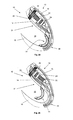
- Fig. 1a to 1e show sectional side views of a first handle 10 according to the invention with different handle size positions of a handle length limitation 11.
- the handle 10 is an integral part of a housing not shown here a line device.
- the handle 10 has a rigid gripping member 12 which is provided for gripping with a single hand not shown here.
- the rigid gripping part 12 has a palmar gripping side 13 and a finger gripping side 14 arranged away from the palmar gripping side 13.
- the gripping part 12 is gripped such that a palm of the hand of the hand at least partially rests against the palm grip side 13.
- finger inner surfaces abut at least partially on the finger gripping side 14.
- the gripping member 10 is ergonomically shaped for gripping with a single hand.
- a handle bar 15 is provided.
- the handle bracket 15 is integrally formed with the gripping member 12 and the finger gripping side 14 facing. In use, finger outside faces the handle bar 15.
- the handle bracket 15 and the gripping part 12 form a handle opening 19 for at least partially inserting and / or passing fingers for gripping the handle 10.
- the handle 10 has an adjustment mechanism 16 for adjusting the handle length limitation 11.
- the handle length limitation 11 is substantially U-shaped. Furthermore, the handle length limitation 11 in the embodiment shown here is rigid. Furthermore, the handle length limitation 11 is arranged on the gripping part 12 for at least partially embracing a small finger and / or a hand edge. By means of the adjusting mechanism 16, the handle length limitation 11 is adjustable for setting a handle length for different hand widths.
- the adjusting mechanism 16 is integrated into the gripping part 12 and at the same time designed as a displacement mechanism and as a pivoting mechanism.
- first latching elements 17 are provided for displacing the handle length limitation 11 in the longitudinal direction of the gripping part 12.
- three first locking elements 17 are provided, which allow three different displacement positions.
- the first latching elements 17 are an integral part of the gripping part 12.
- the handle length limitation 11 has a second latching element 18, which cooperates with one of the first latching elements 17.
- the second latching element 18 is displaceable or latchable together with the handle length limitation 11 into one of the three first latching elements 17.
- the second locking element 18 has a pivot axis 20.
- the handle length limitation 11 can be latched in two different pivot positions in the example shown here.
- more than two pivot positions are conceivable, in particular between two and ten pivot positions.
- this is in the embodiment shown here by about 45 ° between the two pivot positions about the pivot axis 20 pivotally.
- the pivot axis 20 is transversely, in particular at right angles, aligned to a plane which is spanned by the longitudinal orientation of the gripping member 12 and the handle length limitation 11.
- Fig. 1a a maximum handle size position can be seen, in which the handle length limitation 11 is partially integrated in a U-shaped transition region 48 of the gripping member 12 to the gripping bracket 15.
- This transition region 48 is associated with the use of a hand edge and / or a small finger of the handle 10 and the gripping part 12 holding hand.
- the handle size position of Fig. 1b differs from the according to Fig. 1a in that the handle length limitation 11 is pivoted about the pivot axis 20 by approximately 45 ° in order to reduce a handle length for a smaller hand width in the direction of the finger gripping side 14.
- the handle length limitation is in accordance with the handle size position Fig. 1b in a handle size position according to Fig. 1c displaceable.
- Fig. 1d In the handle size position according to Fig. 1d is the handle length limitation from the handle size position according to Fig. 1c pivoted by about 45 ° about the pivot axis 20 of the finger gripping side 14 away.
- the handle size position according to Fig. 1e corresponds to the Fig. 1d , Unlike the Fig. 1a to 1d but are after Fig. 1e further first locking elements 117 are provided, which are associated with the handle bracket 15.
- the handle length limit 11 after Fig. 1e a further second latching element 118.
- This further second latching element 118 is associated with a free end of the handle length limitation 11 and cooperates with in each case one of the further first latching elements 117.
- an adjusting mechanism 116 is provided, which is formed in the embodiment shown here as a pure displacement mechanism.
- the adjusting mechanism 116 may be formed according to the adjustment mechanism 16 at the same time as a sliding and a pivoting mechanism. As a result, a total of 6 handle size positions can be realized.
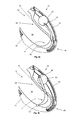
- Fig. 2a and 2b show sectional side views of a second handle 10 according to the invention with different grip sizes of handle length limitation 11. Same features as before carry the same reference numerals. In that regard, reference is also made to the preceding description.
- an adjusting mechanism 21 is provided, which is formed in the embodiment shown here as a displacement mechanism for moving the handle length limitation in the longitudinal direction of the gripping member 12.
- the adjusting mechanism 21 is integrated in the gripping part 12 and has a spindle 22.
- the spindle 22 is aligned with respect to its longitudinal axis in the direction, namely approximately parallel to the longitudinal axis of the gripping member 12.
- the spindle 22 is fixedly connected to an actuating element 23, which is designed here as a rotary wheel or a thumbwheel.
- An axis of rotation of the actuating element 23 is aligned parallel to the longitudinal axis of the spindle 22.
- the actuating element 23 is arranged on the spindle 22 at an end remote from the handle length limit.
- the actuating element 23 is integrated into the gripping part 12 such that in the embodiment shown here an actuating surface of the operating element 23, here a peripheral surface of the knurling wheel, is at least partially freely accessible in the region of the finger grip side 14.
- the actuating surface is flush with the finger gripping side 14.
- the operating element 23 in use conveniently by means of a finger, in particular an index finger or middle finger actuated.
- the actuating surface may also be at least partially freely accessible on a side surface and / or the palm gripping side 15 of the gripping part 12, for example for actuating with a thumb.
- the handle length limitation 11 is associated with a spindle nut 24, which is rotatably guided in the gripping part 12.
- the displacement in the direction of the operating element 23 is limited by means of a stop 49.
- the stop 49 has a flat surface on which a flat surface of the spindle nut 24 can strike. Due to the flat surfaces of the stopper 49 and the spindle nut 24 an undesirable material wear is avoided.
- Fig. 2a That is how it is Fig. 2a to take a maximum handle size position in which the grip size limit 11 is at least partially integrated in a transition region 48 of the gripping member 12 to the handle bracket 15.
- This transition region 48 is in Use of a hand edge and / or a small finger assigned to the handle 10 and the gripping part 12 holding hand.
- the spindle nut 24 abuts against an inside of the transition region 48 in the region of an end of the spindle 22 facing away from the actuating element 23.
- Fig. 2b is to be taken a minimum handle size position, wherein the spindle nut 24 abuts against the stop 49 in the region of the actuator 23 facing the end of the spindle 22.
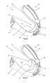
- Fig. 3a and 3b show sectional side views of a third handle 10 according to the invention with different handle sizes of a handle length limitation 11. Same features as before bear the same reference numerals. In that regard, reference is also made to the preceding description.
- the handle length limitation 11 is flexible. A first end of the handle length limitation 11 is assigned to the gripping part 12. In this case, the handle length limitation 11 is pivotable about a pivot axis 20 assigned to the gripping part 12. To attach the handle length limitation 11 on the pivot axis 20, the handle length limitation 11 has an eyelet 27th
- a remote from the first end of the handle length limitation 11 second end is associated with the handle bracket 15 and inserted into this.
- an adjusting mechanism 25 is arranged within the handle bracket 15.
- the adjusting mechanism 25 has an actuating element 23, which is designed here as a push button.
- the actuating element 23 protrudes from the grip bracket 15 in the direction of the finger grip side 14.
- the second end of the handle length limitation 11 is connected to the actuating element 23. Further, the actuating element 23 in the direction of the handle bracket 15 against the force of a restoring element not shown here hineind Wegbar. The actuator 23 engages in a not pressed down state in a fixed to the handle bracket 15 connected tooth row 26 a. As a result, a latching connection is realized. Upon actuation of the operating element 23, namely a pressing down of the actuating element 23 in the direction of the handle bracket 15, the connection between the actuating element 23 and the row of teeth 26 is released.
- the actuating element 23, together with the second end of the handle length limitation 11, can be displaced continuously in a direction substantially parallel to or in the direction of the longitudinal alignment of the handle bracket 15 or of the gripping part 12.
- the actuating element 23 moves automatically in the direction of the gripping part 12 Actuator in the row of teeth 26, whereby a latching connection is realized.
- the adjusting mechanism 25 is designed here as a displacement and adjusting mechanism. This results in a displacement of the handle length limitation 11 by means of the actuating element 23. In this case, simultaneously with the displacement, a pivoting of the handle length limitation 11 takes place about the pivot axis 20.
- the length of the handle length limitation 11 in the region of the handle opening 19 can thus be changed. Due to the different adjustable lengths of the handle length limitation 11 thus different handle size positions are continuously adjustable.
- Fig. 3a That is how it is Fig. 3a to take a maximum handle size position, in which the handle length limitation 11 is integrated into the gripping part 12 and the handle bracket 15.
- the operating element 23 is located at a lower end of the row of teeth 26.
- the handle length limit 11 is in a minimum handle size position.
- the operating element 23 is at an upper end of the row of teeth 26.
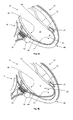
- Fig. 4a and 4b show sectional side views of a fourth handle 10 according to the invention with different grip sizes of a handle length limitation 11. Same features as before carry the same reference numerals. In that regard, reference is also made to the preceding description.
- the handle length limitation 11 is rigid.
- An adjusting mechanism 28 is integrated in the gripping part 12. In this case, a first end of the grip length limit 11 is inserted into the gripping part 12.
- an actuating element 23 is arranged in the gripping part 12, wherein the actuating element 23 is formed in the embodiment shown here as a rotatable hub.
- An actuating surface is here as a peripheral surface of the actuating element 23 at least partially freely accessible in the region of the palm gripping side 13 for actuating the actuating element 23.
- the first end of the handle length limitation 11 is outside the center of the operating element 23 or eccentrically and rotatably connected to the actuating element 23 about a rotation axis 29.
- a remote from the first end of the handle length limitation 11 second end is associated with the handle bracket 15.
- the adjustment mechanism 28 allows continuously adjustable handle size positions.
- the adjusting mechanism 28 is formed as a pivoting mechanism.
- Fig. 4a shows a maximum handle size position, wherein the axis of rotation 29 faces the transition region 48 of the gripping part 12 to the handle bracket 15.
- This transition region 48 is associated with the use of a hand edge and / or a small finger of the handle 10 and the gripping part 12 holding hand.
- the handle length limitation 11 is applied to this transition region 48 in a form-fitting manner.
- a minimum handle size position can be taken, in which the axis of rotation 29 faces away from the transition area 48 from the gripping part 12 to the grip bracket 15.
- the handle length limit 11 compared to Fig. 4a pivoted about the pivot axis 20 away from the transition region 48.
- Fig. 5a and 5b show sectional side views of a fifth handle 10 according to the invention with different handle sizes of a handle length limitation 11. Same features as before carry the same reference numerals. In that regard, reference is also made to the preceding description.
- the adjusting mechanism 30 is arranged in the gripping part 12.
- the adjusting mechanism 30 has a spindle 22 which is rotatably mounted within the gripping member 12 and aligned with respect to the longitudinal axis of the spindle 22 in the direction or approximately parallel to the longitudinal direction of the gripping member 12.
- the spindle 22 is fixedly connected to an actuating element 23, which here - comparable to the embodiment according to Fig. 2a and 2b - Is designed as a rotary wheel or a thumbwheel.
- An axis of rotation of the actuating element 23 is aligned parallel to the longitudinal axis of the spindle 22.
- the actuating element 23 is arranged on the spindle 22 at an end remote from the handle length limitation 11.
- the actuating element 23 is integrated into the gripping part 12 such that in the embodiment shown here, an actuating surface of the control element 23, here a peripheral surface of the knurling wheel, at least partially freely accessible in the palm gripping side 13.
- the operating element 23 is conveniently actuated in use by means of a thumb.
- the actuating surface can also be at least partially freely accessible on a side surface and / or the finger gripping side 14 of the gripping part 12, for example for actuation with a finger.
- the handle length limitation 11 is again rigid.
- a first end of the handle length limitation 11 is inserted into the gripping part 12 and has a tooth comb 31.
- the tooth comb 31 engages at least partially in the spindle 22.
- a remote from the first end of the handle length limitation 11 second end is - comparable to the embodiment according to Fig. 4a and 4b - Associated with the handle bracket 15.
- the second end or the handle length limitation 11 is pivotable about a pivot axis 20 assigned to the handle bracket 15.
- the spindle 22 Upon actuation of the adjusting mechanism 30, which is designed here as a pivoting mechanism, the spindle 22 is simultaneously rotated via a rotation of the actuating element 23. As a result, the handle length limitation 11 can be pivoted about the pivot axis 20 due to the interaction of the toothed comb 31 with the spindle 22. Thus, different grip sizes are continuously adjustable.
- a maximum handle size position is shown, in which the handle length limitation 11 abuts against the transition region 48 from the gripping part 12 to the handle bracket 15.
- This transition region 48 is associated with the use of a hand edge and / or a small finger of the handle 10 and the gripping part 12 holding hand.
- a minimum handle size position is shown in which the handle length limitation 11 compared to Fig. 5a is pivoted about the pivot axis 20 away from the transition region 48.
- Fig. 6a and 6b show sectional side views of a sixth handle 10 according to the invention with different handle sizes of a handle length limitation 11. Same features as before carry the same reference numerals. In that regard, reference is also made to the preceding description.
- the handle length limitation 11 is here according to the embodiment according to Fig. 5a and 5b formed and thus has a first end with a tooth comb 31 and a second end with a pivot axis 20.
- the actuator 23 is also designed here as a rotary wheel or a thumbwheel.
- the actuating element 23 is integrated in the gripping part 12 such that in the embodiment shown here an actuating surface of the operating element 23, in this case a peripheral surface of the knurling wheel, is freely accessible at least partially in the region of the palm grip side 13.
- the axis of the actuating element 23 is arranged parallel to the pivot axis 20 in the embodiment shown here.
- the tooth comb 31 engages in a not-shown here gear element of the actuating element 23 and acts with this together.
- the handle length limitation 11 can be actuated directly with the actuating element 23.
- a spindle is dispensable.
- the handle length limitation 11 is pivotable about the pivot axis 20 via a rotation of the actuating element 23 and due to the interaction of the toothed comb 31 with the actuating element 23.
- different grip sizes are continuously adjustable.
- a maximum handle size position is shown, in which the handle length limitation 11 abuts against the transition region 48 from the gripping part 12 to the handle bracket 15.
- This transition region 48 is associated with the use of a hand edge and / or a small finger of the handle 10 and the gripping part 12 holding hand.
- Fig. 6b a minimum handle size position is shown in which the handle length limitation 11 compared to Fig. 6a is pivoted about the pivot axis 20 away from the transition region 48.
- Fig. 7a and 7b show sectional side views of a seventh handle 10 according to the invention with different grip sizes of a handle length limitation 11. Same features as before carry the same reference numerals. In that regard, reference is also made to the preceding description.
- An adjusting mechanism 33 designed as a pivoting mechanism is assigned to the gripping part 12 in the exemplary embodiment shown here.
- the adjusting mechanism 33 has a locking strip 34 which is embedded in the gripping part 12.
- the locking strip 34 cooperates with locking parts 35, 36, which are assigned to the gripping part 12 facing the end of the handle length limitation 11.
- a remote from the first end of the handle length limitation 11 second end has a pivot axis 20 which is associated with the handle bracket 15.
- Fig. 7a is to take a maximum handle size position, in which the handle length limitation 11 abuts the transition region 48 of the gripping member 12 to the handle bracket 15.
- This transition region 48 is associated with the use of a hand edge and / or a small finger of the handle 10 and the gripping part 12 holding hand.
- Fig. 7b a minimum handle size position is shown in which the handle length limitation 11 compared to Fig. 7a is pivoted about the pivot axis 20 away from the transition region 48.
- Fig. 7c shows a perspective side view of the handle length limitation 11 in the embodiment according to Fig. 7a and 7b . Same features as before bear the same reference numerals. In that regard, reference is also made to the preceding description.
- the handle length limitation 11 has in the embodiment shown here a base body 37 which is U-shaped. As a leg of the U-shaped base body 37 has this two wings 38, 39. At the respective free end of the wing 38, 39 is a locking member 35 and 36, respectively.
- the wings 38, 39 and thus the locking parts 35, 36 are elastically movable towards each other according to the arrows 40, 41.
- FIG. 8a and 8b show sectional side views of a eighth handle 10 according to the invention with different handle sizes of handle length limitation 11. Same features as before carry the same reference numerals. In that regard, reference is also made to the preceding description.
- An adjusting mechanism 43 which is designed as a pivoting mechanism, is likewise assigned to the gripping part 12 in the exemplary embodiment shown here.
- an actuating element 23 is provided, which is designed as a rotary wheel or thumbwheel.
- An axis of rotation of the actuating element 23 is aligned at right angles to a plane which is spanned by the gripping part 12 and the handle bracket 15.
- the operating member 23 is positioned in the gripping part 12 such that a peripheral surface of the operating member 23 as a Operating surface is at least partially freely accessible in the palm gripping side 13.
- a gear 44 is connected to the actuating element 23.
- the position of the axis of rotation of the actuating element 23 is identical to the position of the axis of rotation of the gear 44.
- the gear 44 has a smaller radius than the actuating element 23rd
- a first end of the handle length limitation 11 is inserted into the gripping part 12 and has a toothed rail 45.
- the toothed rail 45 engages in the gear 44 and thus cooperates with this.
- a remote from the first end second end of the handle length limitation 11 has a pivot axis 20 which is associated with the handle bracket 15.
- the toothed wheel 44 connected thereto simultaneously rotates.
- the toothed rail 45 is displaceable or movable in the longitudinal direction of the gripping part 12.
- the handle length limitation 11 can be pivoted about the pivot axis 20 via a rotation of the actuating element 23 and due to the interaction of the toothed wheel 44 with the toothed rail 45.
- different grip sizes are continuously adjustable.
- a minimum handle size position is shown in which the handle length limitation 11 is pivoted about the pivot axis 20 from the transition region 48 of the gripping member 12 to the handle bracket 15 away.
- This transition region 48 is associated with the use of a hand edge and / or a small finger of the handle 10 and the gripping part 12 holding hand.
- Fig. 8b a maximum handle size position is shown, in which the handle length limitation 11 abuts against the transition region 48 from the gripping part 12 to the handle bracket 15.
- Fig. 9a and 9b show sectional side views of another handle 10 according to the invention with different handle sizes of a handle length limitation 11. Same features as before bear the same reference numerals. In that regard, reference is also made to the preceding description.
- An adjusting mechanism 46 is associated with the handle bracket 15 in the embodiment shown here.
- an actuating element 23 is provided, which is formed here spherical.
- the actuator 23 is fixedly connected to a first end of a spindle 22.
- the spindle 22 is rotatably mounted in the handle bracket 15.
- the handle length limitation 11 is associated with a first end of the gripping part 12, wherein the first end by means of a fastening 47 in the region of the finger gripping side 14 fixedly connected to the gripping part 12.
- a remote from the first end second end of the handle length limitation 11 is inserted into the handle bracket 15 and has a toothed rail 45.
- the flexible in this embodiment trained toothed rail 45 engages in the spindle 22 in the spindle 22 and cooperates with this.
- the toothed rail 45 is displaceable or movable within the handle bracket 15.
- the handle length limitation 11 is pivotable about a pivot axis 20 via a rotation of the actuating element 23 and due to the interaction of the spindle 22 with the toothed rail 45.
- the length of the handle length limitation 11 in the region of the handle opening 19 is variable. Due to the different adjustable lengths of the handle length limitation 11 thus different handle size positions are continuously adjustable.
- the pivot axis 20 in the embodiment shown here is not material, but virtually formed and is located in the region of a fastening 47 for the handle length limitation in the region of the handle bracket 15th
- the adjusting mechanism 46 is formed in the embodiment shown here as a displacement and adjustment mechanism. In this case, a displacement by means of the actuating element 23 in cooperation with the spindle 22 and the toothed rail 45. At the same time there is a pivoting about the pivot axis 20th
- Fig. 9a is to take a maximum handle size position, in which the flexibly formed in this embodiment grip length limitation 11 abuts the transition region 48 of the gripping member 12 to the handle bracket 15.
- This transition region 48 is associated with the use of a hand edge and / or a small finger of the handle 10 and the gripping part 12 holding hand.
- Fig. 9b a minimum handle size position is shown in which the handle length limitation 11 compared to Fig. 9a about a pivot axis 20 from Transition region 48 is pivoted away.
- the pivot axis 20 is assigned to the gripping part 12.
- the handle 10 may be integrated in a housing of a linen device.
- the linen device can be provided for rolling up and unrolling a leash.
- the line or the linen device is used to guide an animal, such as a dog or a cat.
- the line can be guided within the housing on a line roller and be led out of the housing by means of a linen opening.
- a brake button can be provided to stop the Abrollvorganges and thus to limit the unrolled line length.
Landscapes
- Life Sciences & Earth Sciences (AREA)
- Environmental Sciences (AREA)
- Animal Husbandry (AREA)
- Biodiversity & Conservation Biology (AREA)
- Purses, Travelling Bags, Baskets, Or Suitcases (AREA)
- Food-Manufacturing Devices (AREA)
- Prostheses (AREA)
- Steering Devices For Bicycles And Motorcycles (AREA)
- Harvester Elements (AREA)
- Holders For Apparel And Elements Relating To Apparel (AREA)
Applications Claiming Priority (1)
| Application Number | Priority Date | Filing Date | Title |
|---|---|---|---|
| DE102011114640A DE102011114640B3 (de) | 2011-10-04 | 2011-10-04 | Griff zum Ergreifen mit einer Hand und eine Leineneinrichtung mit einem solchen Griff |
Publications (3)
| Publication Number | Publication Date |
|---|---|
| EP2578079A2 true EP2578079A2 (fr) | 2013-04-10 |
| EP2578079A3 EP2578079A3 (fr) | 2013-12-11 |
| EP2578079B1 EP2578079B1 (fr) | 2017-12-13 |
Family
ID=46968070
Family Applications (1)
| Application Number | Title | Priority Date | Filing Date |
|---|---|---|---|
| EP12187054.7A Active EP2578079B1 (fr) | 2011-10-04 | 2012-10-02 | Poignée de serrage d'une main et un dispositif à laisse équipé d'une telle poignée |
Country Status (9)
| Country | Link |
|---|---|
| US (1) | US8826865B2 (fr) |
| EP (1) | EP2578079B1 (fr) |
| JP (1) | JP5504318B2 (fr) |
| CN (1) | CN103026974B (fr) |
| BR (1) | BR102012025372A2 (fr) |
| DE (1) | DE102011114640B3 (fr) |
| DK (1) | DK2578079T3 (fr) |
| ES (1) | ES2660250T3 (fr) |
| RU (1) | RU2540564C2 (fr) |
Families Citing this family (11)
| Publication number | Priority date | Publication date | Assignee | Title |
|---|---|---|---|---|
| US8678221B2 (en) | 2010-04-28 | 2014-03-25 | Crown Packaging Technology, Inc. | Beverage container lid with mouth opening and separate push in vent |
| US10434343B1 (en) * | 2011-03-14 | 2019-10-08 | Climb Tech, Llc | Quick-release attachment point for fall protection |
| US9480241B2 (en) | 2011-07-05 | 2016-11-01 | Eric James Holmstrom | Retractable leash system |
| US9609851B2 (en) | 2012-10-31 | 2017-04-04 | II John Robert Harris | Emergency leash |
| US10246229B2 (en) | 2013-03-14 | 2019-04-02 | Crown Packaging Technology, Inc. | Vented beverage can and can end |
| USD731887S1 (en) | 2013-03-14 | 2015-06-16 | Crown Packaging Technology, Inc. | Vented beverage can end |
| US9403628B2 (en) | 2013-03-14 | 2016-08-02 | Crown Packaging Technology, Inc. | Vented beverage can and can end |
| KR101911637B1 (ko) | 2017-07-04 | 2018-10-24 | 방청우 | 기능성 애견용 자동 리드줄 장치 |
| US12219930B2 (en) | 2019-12-30 | 2025-02-11 | Joseph E. Kovarik | Detachable cover for a retractable dog leash |
| US12532867B2 (en) | 2023-08-25 | 2026-01-27 | Jacob Thompson | One-handed leash with quick-release mechanism |
| EP4646925A1 (fr) * | 2024-05-06 | 2025-11-12 | Diligent Verwaltung GmbH | Dispositif de laisse à enrouleur pour dérouler et enrouler une laisse pour animal |
Citations (1)
| Publication number | Priority date | Publication date | Assignee | Title |
|---|---|---|---|---|
| DE29904882U1 (de) | 1999-03-17 | 1999-06-02 | Flexi Bogdahn Technik GmbH & Co. KG, 22941 Bargteheide | Leineneinrichtung für eine auf- und abrollbare Leine zum Führen von Tieren |
Family Cites Families (15)
| Publication number | Priority date | Publication date | Assignee | Title |
|---|---|---|---|---|
| US1338376A (en) * | 1919-06-20 | 1920-04-27 | Kocha Jacob | Monkey-wrench |
| SU1639553A1 (ru) * | 1989-04-19 | 1991-04-07 | Д.Б. Смирнов | Кассета дл поводка |
| CN2328182Y (zh) * | 1998-03-20 | 1999-07-14 | 孟毅 | 伸缩制动拉绳 |
| ITVR20000069A1 (it) * | 2000-07-21 | 2002-01-21 | Ferplast Spa | Guinzaglio con impugnatura ergonomica |
| RU2004126869A (ru) * | 2002-02-20 | 2006-02-27 | Васко МАНЧИНИ (IT) | Поводок для собаки, снабженный жесткой ручкой, содержащей средство для сбора и удаления экскрементов животного |
| JP3777139B2 (ja) * | 2002-05-01 | 2006-05-24 | ドギーマンハヤシ株式会社 | ペット用リード |
| US7044080B2 (en) * | 2003-10-23 | 2006-05-16 | Billy Rabello | Dog leash handle |
| FR2862544B1 (fr) * | 2003-11-24 | 2006-02-17 | Zedel | Piolet pour l'alpinisme avec poignee de prehension reglable |
| CN2760953Y (zh) * | 2005-01-07 | 2006-03-01 | 王崇义 | 犬控制索 |
| US20070006821A1 (en) * | 2005-07-08 | 2007-01-11 | Mitnick David K | Hand-held pet lead with adjustable handle |
| JP2007307626A (ja) * | 2006-05-16 | 2007-11-29 | Hitachi Koki Co Ltd | 電動工具 |
| CN101518211A (zh) * | 2008-02-29 | 2009-09-02 | 哈茨山公司 | 可伸缩的环状宠物牵带 |
| US20110083617A1 (en) * | 2009-10-09 | 2011-04-14 | Eric Townsend | Device for restraining animals to fixtures |
| CN101720677A (zh) * | 2010-01-19 | 2010-06-09 | 曾春旭 | 多功能牵狗器 |
| US9480241B2 (en) * | 2011-07-05 | 2016-11-01 | Eric James Holmstrom | Retractable leash system |
-
2011
- 2011-10-04 DE DE102011114640A patent/DE102011114640B3/de not_active Expired - Fee Related
-
2012
- 2012-10-02 EP EP12187054.7A patent/EP2578079B1/fr active Active
- 2012-10-02 DK DK12187054.7T patent/DK2578079T3/en active
- 2012-10-02 ES ES12187054.7T patent/ES2660250T3/es active Active
- 2012-10-03 JP JP2012221040A patent/JP5504318B2/ja active Active
- 2012-10-03 RU RU2012142129/13A patent/RU2540564C2/ru active
- 2012-10-04 BR BR102012025372-0A patent/BR102012025372A2/pt not_active IP Right Cessation
- 2012-10-04 US US13/644,314 patent/US8826865B2/en active Active
- 2012-10-08 CN CN201210378027.5A patent/CN103026974B/zh active Active
Patent Citations (1)
| Publication number | Priority date | Publication date | Assignee | Title |
|---|---|---|---|---|
| DE29904882U1 (de) | 1999-03-17 | 1999-06-02 | Flexi Bogdahn Technik GmbH & Co. KG, 22941 Bargteheide | Leineneinrichtung für eine auf- und abrollbare Leine zum Führen von Tieren |
Also Published As
| Publication number | Publication date |
|---|---|
| CN103026974A (zh) | 2013-04-10 |
| RU2540564C2 (ru) | 2015-02-10 |
| EP2578079A3 (fr) | 2013-12-11 |
| JP2013078309A (ja) | 2013-05-02 |
| CN103026974B (zh) | 2015-03-04 |
| US20130081580A1 (en) | 2013-04-04 |
| US8826865B2 (en) | 2014-09-09 |
| RU2012142129A (ru) | 2014-04-27 |
| EP2578079B1 (fr) | 2017-12-13 |
| DK2578079T3 (en) | 2018-03-12 |
| JP5504318B2 (ja) | 2014-05-28 |
| BR102012025372A2 (pt) | 2013-12-17 |
| ES2660250T3 (es) | 2018-03-21 |
| DE102011114640B3 (de) | 2013-01-03 |
Similar Documents
| Publication | Publication Date | Title |
|---|---|---|
| EP2578079B1 (fr) | Poignée de serrage d'une main et un dispositif à laisse équipé d'une telle poignée | |
| DE102011110835B4 (de) | Vorrichtung zum Aufrollen und Abrollen einer Leine | |
| DE102006037743B4 (de) | Ratschenzurrgurt-Vorrichtung | |
| DE102015106562B4 (de) | Presszange | |
| EP1972193B1 (fr) | Laisse enroulable et déroulable mécaniquement pour mener des animaux | |
| DE102012208542B4 (de) | Vorrichtung zum Binden eines Schnürsenkels | |
| EP3272477A1 (fr) | Couteau | |
| EP2007553B1 (fr) | Outil à main à ouverture automatique | |
| EP2413799B1 (fr) | Dispositif à lancette à réglage de la profondeur d'une piqûre | |
| DE4143410A1 (de) | Sicherheitsbindung | |
| EP3419529B1 (fr) | Dispositif de ligature pour parties du corps | |
| EP1050378A2 (fr) | Pince actionnée à une main | |
| EP0093445A1 (fr) | Boîtier portable pour laisse | |
| DE202019101474U1 (de) | Ratschengurtspanner | |
| WO2005113292A1 (fr) | Systeme de store a element coulissant freine | |
| DE3345725C2 (de) | Vorrichtung zum Auslösen des Schiebers eines Schirmes | |
| EP1415833A2 (fr) | Rail de guidage, en particulier pour un store à enrouleur dans un véhicule | |
| EP3222135B1 (fr) | Taille haie avec gachette a force de maintien reduite | |
| DE102012211200A1 (de) | Greifinstrument | |
| EP2363248B1 (fr) | Support manuel pour le montage sur le manche d'un piolet d'alpiniste | |
| DE2922560C2 (de) | Einrichtung zum Betätigen eines Umwerfers einer Fahrrad-Kettenschaltung | |
| DE3013953A1 (de) | Schnallenverschluss fuer schuhe, insbesondere fuer ski- oder bergstiefel | |
| DE2845485A1 (de) | Einstellvorrichtung mit einem um eine achse schwenkbaren einstellorgan | |
| DE102013209741A1 (de) | Druckknopf-betätigter abroller für klebeband | |
| DE202009001163U1 (de) | Sportstock |
Legal Events
| Date | Code | Title | Description |
|---|---|---|---|
| PUAI | Public reference made under article 153(3) epc to a published international application that has entered the european phase |
Free format text: ORIGINAL CODE: 0009012 |
|
| AK | Designated contracting states |
Kind code of ref document: A2 Designated state(s): AL AT BE BG CH CY CZ DE DK EE ES FI FR GB GR HR HU IE IS IT LI LT LU LV MC MK MT NL NO PL PT RO RS SE SI SK SM TR |
|
| AX | Request for extension of the european patent |
Extension state: BA ME |
|
| PUAL | Search report despatched |
Free format text: ORIGINAL CODE: 0009013 |
|
| AK | Designated contracting states |
Kind code of ref document: A3 Designated state(s): AL AT BE BG CH CY CZ DE DK EE ES FI FR GB GR HR HU IE IS IT LI LT LU LV MC MK MT NL NO PL PT RO RS SE SI SK SM TR |
|
| AX | Request for extension of the european patent |
Extension state: BA ME |
|
| RIC1 | Information provided on ipc code assigned before grant |
Ipc: A01K 27/00 20060101AFI20131101BHEP |
|
| 17P | Request for examination filed |
Effective date: 20140611 |
|
| RBV | Designated contracting states (corrected) |
Designated state(s): AL AT BE BG CH CY CZ DE DK EE ES FI FR GB GR HR HU IE IS IT LI LT LU LV MC MK MT NL NO PL PT RO RS SE SI SK SM TR |
|
| GRAP | Despatch of communication of intention to grant a patent |
Free format text: ORIGINAL CODE: EPIDOSNIGR1 |
|
| INTG | Intention to grant announced |
Effective date: 20170619 |
|
| GRAS | Grant fee paid |
Free format text: ORIGINAL CODE: EPIDOSNIGR3 |
|
| GRAA | (expected) grant |
Free format text: ORIGINAL CODE: 0009210 |
|
| AK | Designated contracting states |
Kind code of ref document: B1 Designated state(s): AL AT BE BG CH CY CZ DE DK EE ES FI FR GB GR HR HU IE IS IT LI LT LU LV MC MK MT NL NO PL PT RO RS SE SI SK SM TR |
|
| REG | Reference to a national code |
Ref country code: GB Ref legal event code: FG4D Free format text: NOT ENGLISH |
|
| REG | Reference to a national code |
Ref country code: AT Ref legal event code: REF Ref document number: 953478 Country of ref document: AT Kind code of ref document: T Effective date: 20171215 Ref country code: CH Ref legal event code: EP |
|
| REG | Reference to a national code |
Ref country code: IE Ref legal event code: FG4D Free format text: LANGUAGE OF EP DOCUMENT: GERMAN |
|
| REG | Reference to a national code |
Ref country code: DE Ref legal event code: R096 Ref document number: 502012011808 Country of ref document: DE |
|
| REG | Reference to a national code |
Ref country code: DK Ref legal event code: T3 Effective date: 20180305 |
|
| REG | Reference to a national code |
Ref country code: CH Ref legal event code: NV Representative=s name: ROSENICH PAUL; KUENSCH JOACHIM PATENTBUERO PAU, LI |
|
| REG | Reference to a national code |
Ref country code: SE Ref legal event code: TRGR |
|
| REG | Reference to a national code |
Ref country code: ES Ref legal event code: FG2A Ref document number: 2660250 Country of ref document: ES Kind code of ref document: T3 Effective date: 20180321 Ref country code: NL Ref legal event code: FP |
|
| REG | Reference to a national code |
Ref country code: LT Ref legal event code: MG4D |
|
| PG25 | Lapsed in a contracting state [announced via postgrant information from national office to epo] |
Ref country code: NO Free format text: LAPSE BECAUSE OF FAILURE TO SUBMIT A TRANSLATION OF THE DESCRIPTION OR TO PAY THE FEE WITHIN THE PRESCRIBED TIME-LIMIT Effective date: 20180313 Ref country code: LT Free format text: LAPSE BECAUSE OF FAILURE TO SUBMIT A TRANSLATION OF THE DESCRIPTION OR TO PAY THE FEE WITHIN THE PRESCRIBED TIME-LIMIT Effective date: 20171213 |
|
| PG25 | Lapsed in a contracting state [announced via postgrant information from national office to epo] |
Ref country code: RS Free format text: LAPSE BECAUSE OF FAILURE TO SUBMIT A TRANSLATION OF THE DESCRIPTION OR TO PAY THE FEE WITHIN THE PRESCRIBED TIME-LIMIT Effective date: 20171213 Ref country code: LV Free format text: LAPSE BECAUSE OF FAILURE TO SUBMIT A TRANSLATION OF THE DESCRIPTION OR TO PAY THE FEE WITHIN THE PRESCRIBED TIME-LIMIT Effective date: 20171213 Ref country code: GR Free format text: LAPSE BECAUSE OF FAILURE TO SUBMIT A TRANSLATION OF THE DESCRIPTION OR TO PAY THE FEE WITHIN THE PRESCRIBED TIME-LIMIT Effective date: 20180314 Ref country code: BG Free format text: LAPSE BECAUSE OF FAILURE TO SUBMIT A TRANSLATION OF THE DESCRIPTION OR TO PAY THE FEE WITHIN THE PRESCRIBED TIME-LIMIT Effective date: 20180313 Ref country code: HR Free format text: LAPSE BECAUSE OF FAILURE TO SUBMIT A TRANSLATION OF THE DESCRIPTION OR TO PAY THE FEE WITHIN THE PRESCRIBED TIME-LIMIT Effective date: 20171213 |
|
| PG25 | Lapsed in a contracting state [announced via postgrant information from national office to epo] |
Ref country code: SK Free format text: LAPSE BECAUSE OF FAILURE TO SUBMIT A TRANSLATION OF THE DESCRIPTION OR TO PAY THE FEE WITHIN THE PRESCRIBED TIME-LIMIT Effective date: 20171213 Ref country code: EE Free format text: LAPSE BECAUSE OF FAILURE TO SUBMIT A TRANSLATION OF THE DESCRIPTION OR TO PAY THE FEE WITHIN THE PRESCRIBED TIME-LIMIT Effective date: 20171213 Ref country code: CY Free format text: LAPSE BECAUSE OF FAILURE TO SUBMIT A TRANSLATION OF THE DESCRIPTION OR TO PAY THE FEE WITHIN THE PRESCRIBED TIME-LIMIT Effective date: 20171213 |
|
| PG25 | Lapsed in a contracting state [announced via postgrant information from national office to epo] |
Ref country code: RO Free format text: LAPSE BECAUSE OF FAILURE TO SUBMIT A TRANSLATION OF THE DESCRIPTION OR TO PAY THE FEE WITHIN THE PRESCRIBED TIME-LIMIT Effective date: 20171213 Ref country code: IS Free format text: LAPSE BECAUSE OF FAILURE TO SUBMIT A TRANSLATION OF THE DESCRIPTION OR TO PAY THE FEE WITHIN THE PRESCRIBED TIME-LIMIT Effective date: 20180413 Ref country code: SM Free format text: LAPSE BECAUSE OF FAILURE TO SUBMIT A TRANSLATION OF THE DESCRIPTION OR TO PAY THE FEE WITHIN THE PRESCRIBED TIME-LIMIT Effective date: 20171213 Ref country code: PL Free format text: LAPSE BECAUSE OF FAILURE TO SUBMIT A TRANSLATION OF THE DESCRIPTION OR TO PAY THE FEE WITHIN THE PRESCRIBED TIME-LIMIT Effective date: 20171213 |
|
| REG | Reference to a national code |
Ref country code: DE Ref legal event code: R097 Ref document number: 502012011808 Country of ref document: DE |
|
| PG25 | Lapsed in a contracting state [announced via postgrant information from national office to epo] |
Ref country code: MT Free format text: LAPSE BECAUSE OF FAILURE TO SUBMIT A TRANSLATION OF THE DESCRIPTION OR TO PAY THE FEE WITHIN THE PRESCRIBED TIME-LIMIT Effective date: 20171213 |
|
| PLBE | No opposition filed within time limit |
Free format text: ORIGINAL CODE: 0009261 |
|
| STAA | Information on the status of an ep patent application or granted ep patent |
Free format text: STATUS: NO OPPOSITION FILED WITHIN TIME LIMIT |
|
| REG | Reference to a national code |
Ref country code: FR Ref legal event code: PLFP Year of fee payment: 7 |
|
| 26N | No opposition filed |
Effective date: 20180914 |
|
| PG25 | Lapsed in a contracting state [announced via postgrant information from national office to epo] |
Ref country code: SI Free format text: LAPSE BECAUSE OF FAILURE TO SUBMIT A TRANSLATION OF THE DESCRIPTION OR TO PAY THE FEE WITHIN THE PRESCRIBED TIME-LIMIT Effective date: 20171213 |
|
| PG25 | Lapsed in a contracting state [announced via postgrant information from national office to epo] |
Ref country code: MC Free format text: LAPSE BECAUSE OF FAILURE TO SUBMIT A TRANSLATION OF THE DESCRIPTION OR TO PAY THE FEE WITHIN THE PRESCRIBED TIME-LIMIT Effective date: 20171213 Ref country code: LU Free format text: LAPSE BECAUSE OF NON-PAYMENT OF DUE FEES Effective date: 20181002 |
|
| PGFP | Annual fee paid to national office [announced via postgrant information from national office to epo] |
Ref country code: IE Payment date: 20191021 Year of fee payment: 8 |
|
| PG25 | Lapsed in a contracting state [announced via postgrant information from national office to epo] |
Ref country code: TR Free format text: LAPSE BECAUSE OF FAILURE TO SUBMIT A TRANSLATION OF THE DESCRIPTION OR TO PAY THE FEE WITHIN THE PRESCRIBED TIME-LIMIT Effective date: 20171213 |
|
| PG25 | Lapsed in a contracting state [announced via postgrant information from national office to epo] |
Ref country code: PT Free format text: LAPSE BECAUSE OF FAILURE TO SUBMIT A TRANSLATION OF THE DESCRIPTION OR TO PAY THE FEE WITHIN THE PRESCRIBED TIME-LIMIT Effective date: 20171213 |
|
| PG25 | Lapsed in a contracting state [announced via postgrant information from national office to epo] |
Ref country code: HU Free format text: LAPSE BECAUSE OF FAILURE TO SUBMIT A TRANSLATION OF THE DESCRIPTION OR TO PAY THE FEE WITHIN THE PRESCRIBED TIME-LIMIT; INVALID AB INITIO Effective date: 20121002 Ref country code: MK Free format text: LAPSE BECAUSE OF NON-PAYMENT OF DUE FEES Effective date: 20171213 |
|
| PG25 | Lapsed in a contracting state [announced via postgrant information from national office to epo] |
Ref country code: AL Free format text: LAPSE BECAUSE OF FAILURE TO SUBMIT A TRANSLATION OF THE DESCRIPTION OR TO PAY THE FEE WITHIN THE PRESCRIBED TIME-LIMIT Effective date: 20171213 |
|
| REG | Reference to a national code |
Ref country code: CH Ref legal event code: PCAR Free format text: NEW ADDRESS: ROTENBODENSTRASSE 12, 9497 TRIESENBERG (LI) |
|
| REG | Reference to a national code |
Ref country code: DE Ref legal event code: R082 Ref document number: 502012011808 Country of ref document: DE Representative=s name: TAPPE, UDO, DIPL.-PHYS. DR.RER.NAT., DE |
|
| PG25 | Lapsed in a contracting state [announced via postgrant information from national office to epo] |
Ref country code: IE Free format text: LAPSE BECAUSE OF NON-PAYMENT OF DUE FEES Effective date: 20201002 |
|
| REG | Reference to a national code |
Ref country code: GB Ref legal event code: 732E Free format text: REGISTERED BETWEEN 20220106 AND 20220112 |
|
| P01 | Opt-out of the competence of the unified patent court (upc) registered |
Effective date: 20230515 |
|
| PGFP | Annual fee paid to national office [announced via postgrant information from national office to epo] |
Ref country code: AT Payment date: 20241024 Year of fee payment: 13 |
|
| PGFP | Annual fee paid to national office [announced via postgrant information from national office to epo] |
Ref country code: CH Payment date: 20241101 Year of fee payment: 13 |
|
| PGFP | Annual fee paid to national office [announced via postgrant information from national office to epo] |
Ref country code: CZ Payment date: 20250919 Year of fee payment: 14 |
|
| PGFP | Annual fee paid to national office [announced via postgrant information from national office to epo] |
Ref country code: NL Payment date: 20251023 Year of fee payment: 14 |
|
| PGFP | Annual fee paid to national office [announced via postgrant information from national office to epo] |
Ref country code: DE Payment date: 20251031 Year of fee payment: 14 |
|
| PGFP | Annual fee paid to national office [announced via postgrant information from national office to epo] |
Ref country code: GB Payment date: 20251024 Year of fee payment: 14 |
|
| PGFP | Annual fee paid to national office [announced via postgrant information from national office to epo] |
Ref country code: FI Payment date: 20251022 Year of fee payment: 14 Ref country code: DK Payment date: 20251023 Year of fee payment: 14 Ref country code: IT Payment date: 20251031 Year of fee payment: 14 |
|
| PGFP | Annual fee paid to national office [announced via postgrant information from national office to epo] |
Ref country code: FR Payment date: 20251024 Year of fee payment: 14 |
|
| PGFP | Annual fee paid to national office [announced via postgrant information from national office to epo] |
Ref country code: BE Payment date: 20251022 Year of fee payment: 14 |
|
| PGFP | Annual fee paid to national office [announced via postgrant information from national office to epo] |
Ref country code: SE Payment date: 20251023 Year of fee payment: 14 |
|
| PGFP | Annual fee paid to national office [announced via postgrant information from national office to epo] |
Ref country code: ES Payment date: 20251114 Year of fee payment: 14 |