EP2578320A1 - Selbstabdichtender Ausgabeeinsatz und Montierverfahren dafür - Google Patents
Selbstabdichtender Ausgabeeinsatz und Montierverfahren dafür Download PDFInfo
- Publication number
- EP2578320A1 EP2578320A1 EP12186136.3A EP12186136A EP2578320A1 EP 2578320 A1 EP2578320 A1 EP 2578320A1 EP 12186136 A EP12186136 A EP 12186136A EP 2578320 A1 EP2578320 A1 EP 2578320A1
- Authority
- EP
- European Patent Office
- Prior art keywords
- dispenser
- reed valve
- axial hole
- fluid
- plug
- Prior art date
- Legal status (The legal status is an assumption and is not a legal conclusion. Google has not performed a legal analysis and makes no representation as to the accuracy of the status listed.)
- Granted
Links
Images




Classifications
-
- B—PERFORMING OPERATIONS; TRANSPORTING
- B05—SPRAYING OR ATOMISING IN GENERAL; APPLYING FLUENT MATERIALS TO SURFACES, IN GENERAL
- B05B—SPRAYING APPARATUS; ATOMISING APPARATUS; NOZZLES
- B05B11/00—Single-unit hand-held apparatus in which flow of contents is produced by the muscular force of the operator at the moment of use
- B05B11/01—Single-unit hand-held apparatus in which flow of contents is produced by the muscular force of the operator at the moment of use characterised by the means producing the flow
- B05B11/04—Deformable containers producing the flow, e.g. squeeze bottles
- B05B11/047—Deformable containers producing the flow, e.g. squeeze bottles characterised by the outlet or venting means
-
- B—PERFORMING OPERATIONS; TRANSPORTING
- B05—SPRAYING OR ATOMISING IN GENERAL; APPLYING FLUENT MATERIALS TO SURFACES, IN GENERAL
- B05B—SPRAYING APPARATUS; ATOMISING APPARATUS; NOZZLES
- B05B11/00—Single-unit hand-held apparatus in which flow of contents is produced by the muscular force of the operator at the moment of use
- B05B11/0005—Components or details
- B05B11/0062—Outlet valves actuated by the pressure of the fluid to be sprayed
- B05B11/007—Outlet valves actuated by the pressure of the fluid to be sprayed being opened by deformation of a sealing element made of resiliently deformable material, e.g. flaps, skirts, duck-bill valves
-
- B—PERFORMING OPERATIONS; TRANSPORTING
- B05—SPRAYING OR ATOMISING IN GENERAL; APPLYING FLUENT MATERIALS TO SURFACES, IN GENERAL
- B05B—SPRAYING APPARATUS; ATOMISING APPARATUS; NOZZLES
- B05B11/00—Single-unit hand-held apparatus in which flow of contents is produced by the muscular force of the operator at the moment of use
- B05B11/0005—Components or details
- B05B11/0062—Outlet valves actuated by the pressure of the fluid to be sprayed
- B05B11/0072—A valve member forming part of an outlet opening
-
- B—PERFORMING OPERATIONS; TRANSPORTING
- B65—CONVEYING; PACKING; STORING; HANDLING THIN OR FILAMENTARY MATERIAL
- B65D—CONTAINERS FOR STORAGE OR TRANSPORT OF ARTICLES OR MATERIALS, e.g. BAGS, BARRELS, BOTTLES, BOXES, CANS, CARTONS, CRATES, DRUMS, JARS, TANKS, HOPPERS, FORWARDING CONTAINERS; ACCESSORIES, CLOSURES, OR FITTINGS THEREFOR; PACKAGING ELEMENTS; PACKAGES
- B65D51/00—Closures not otherwise provided for
- B65D51/16—Closures not otherwise provided for with means for venting air or gas
- B65D51/1633—Closures not otherwise provided for with means for venting air or gas whereby venting occurs by automatic opening of the closure, container or other element
- B65D51/1644—Closures not otherwise provided for with means for venting air or gas whereby venting occurs by automatic opening of the closure, container or other element the element being a valve
-
- Y—GENERAL TAGGING OF NEW TECHNOLOGICAL DEVELOPMENTS; GENERAL TAGGING OF CROSS-SECTIONAL TECHNOLOGIES SPANNING OVER SEVERAL SECTIONS OF THE IPC; TECHNICAL SUBJECTS COVERED BY FORMER USPC CROSS-REFERENCE ART COLLECTIONS [XRACs] AND DIGESTS
- Y10—TECHNICAL SUBJECTS COVERED BY FORMER USPC
- Y10S—TECHNICAL SUBJECTS COVERED BY FORMER USPC CROSS-REFERENCE ART COLLECTIONS [XRACs] AND DIGESTS
- Y10S215/00—Bottles and jars
- Y10S215/902—Vent
Definitions
- the field of the disclosure relates generally to caps for fluid dispensers, and more specifically to self-sealing caps for chemical dispensers.
- Some known fluid storage dispensers include a flexible body that may discharge a liquid contained therein through an opening in the dispenser when a squeezing pressure, for example from an operator's hand is applied.
- Some known dispensers may include a sealing means that provides a subsequent sealing action after the pressure is removed, but such dispensers require a two-handed arrangement with these dispensers wherein the closing action must be done by the operator's second hand.
- Some other known dispensers simply require that each hand manipulate one of two parts to facilitate closing the fluid dispenser.
- a known housing for a control valve used on a squeeze type fluid dispensing container includes a first check valve fixedly coupled inside a housing. When the first check valve is opened, fluid flow is permitted through an opening and out of a tube in the housing. A second such check valve is fixedly coupled inside the first check valve, and when opened, facilitates channeling the fluid flow from the tube into the housing, then through an opening in the housing and back into the dispenser.
- Some other known fluid dispensers provide a dual-valve system. Such dual valve assemblies respond to differences in pressure, and cooperate to dispense the fluid from the dispenser, or seal the openings thereof during non-use.
- the cap may include a valve positioned within the dispenser outlet which is cleaned of material at the end of the dispensing period by the action of the dispenser mechanism herein.
- dual valve assemblies are not directly exposed to the atmosphere, and fail to allow ambient air into the dispenser to normalize the squeezable dispenser, while maintaining the liquid, and any gaseous product associated with the liquid, within the dispenser during periods of non-use.
- a fluid dispenser in one aspect, includes a dispenser made from a flexible material and having a body portion and a cylindrical mouth portion extending from the body portion, the mouth portion defining an opening further defining a lip extending about the opening, a cap operable to engage the mouth portion of the dispenser, the cap comprising an aperture therethrough operable to dispense a fluid stored within the dispenser, and a cylindrical insert sized for placement within the opening between the mouth portion and the cap.
- the cylindrical insert includes a substantially solid plug having a first axial hole therethrough and a second axial hole therethrough, a first reed valve operably attached to the plug to close the first axial hole from an outside of the dispenser, and a second reed valve operably attached to the plug to close the second axial hole from an inside of the dispenser.
- an insert sized for placement within an opening of a dispenser includes a substantially solid plug having a first surface, a second surface, and first and second axial holes extending from the first surface to the second surface, a first reed valve operably attached to the first surface of the plug to close the first axial hole, and a second reed valve operably attached to the second surface of the plug to close the second axial hole.
- a method dispensing a fluid from a flexible dispenser includes applying a positive pressure to the dispenser to force the fluid through a first axial hole formed in a plug placed in a opening of the dispenser, the pressure causing a first reed valve mounted on a side of the plug opposite the fluid storage to move away from the first axial hole to allow the fluid to pass through, the positive pressure further causing a second reed valve on a side of the plug where the fluid is contained to maintain placement to substantially seal a second axial hole formed in the plug, releasing the positive pressure to allow the first reed valve to return to a position that substantially seals the first axial hole and allows the second reed valve to open thereby allowing air to enter the dispenser through the second axial hole until a difference in pressure between an interior and an exterior of the dispenser is reduced to substantially zero, and allowing the second reed valve to substantially reseal the second axial hole.
- FIG. 1 is schematic illustration of an exemplary dispenser 10 used for storing an amount of fluid 12 therein.
- Dispenser 10 includes a body portion 14 for use in containing and storing fluid 12.
- dispenser 10 is fabricated from a flexible material, such as, but not limited to a polymer or plastic.
- a mouth portion 16 extends from body portion 14 and includes an orifice 17 that is sized and oriented to enable fluid 12 to be introduced into or out of dispenser 10.
- Mouth portion 16 includes an outer surface 18 configured to be coupled to a cap 20.
- Orifice 17 defines a lip 19 at an end of the mouth portion.
- outer surface 18 includes a plurality of threads 22 that are sized and oriented to threadably couple with a plurality of corresponding threads 24 disposed on cap 20.
- cap 20 may be coupled to mouth portion 16 over outer surface 18 using any coupling method such as, but not limited to, friction fitting, a tab and groove combination, and/or with any coupling configuration that enables dispenser 10 to function as described herein.
- cap 20 includes an inner surface 26 and an outer surface 28.
- Cap 20 includes a substantially cylindrical cross-section that includes a first end 30 and a second end 32.
- First end 30 of cap 20 includes an opening 34 that is sized and oriented to receive mouth portion 16 therein.
- Cap 20 includes a substantially flat top portion 40 that extends across second end 32 of cap 20.
- cap assembly 20 includes a tip 42 rotatable with respect to and extending from flat top portion 40 of cap 20, and includes an aperture 46 therethrough operable to dispense fluid 12 stored within dispenser 10. In one orientation tip 42 is operable for dispensing of fluid 12, and in another orientation (not shown) tip 42 is not operable for dispensing of fluid 12 as is well known. Alternatively, cap 20 may not include tip 42, but may simply include an aperture (not shown) therethrough that is sized and oriented to enable dispensing fluid 12 from dispenser 10 as described in more detail herein.
- Self sealing dispenser insert 50 is shown disposed between cap 20 and dispenser 10 in Figure 1 .
- Self sealing dispenser insert 50 in the illustrated embodiment is a cylindrical insert sized for placement within the orifice 17, or opening, substantially between the mouth portion 16 and the cap 20.
- self sealing dispenser insert 50 is a substantially solid plug 52 that includes a protrusion 54 about a perimeter at a top 56 thereof.
- the protrusion 54 is operable for engaging the lip 19 of the mouth portion 16, essentially forming a washer between the dispenser 10 and the cap 20.
- the plug 52 is fabricated from a plastic.
- self sealing dispenser insert 50 includes a first axial hole 60 and a second axial hole 62 formed through the plug 52.
- a first reed valve 100 is operably attached to the plug 52 positioned to close and/or substantially seal the first axial hole 60 from an outside of the dispenser 10.
- the first reed valve 100 applies a biasing force for closing the first axial hole 60 in the absence of an externally applied pressure.
- a reed retainer 102 is also operably attached to the plug 52. Reed retainer 102 is operable to place a further positive pressure onto the first reed valve 100 with respect to the first axial hole 60, helping to maintain the seal between first reed valve 100 and plug 52 when the dispenser insert 50 is operatively deployed.
- a second reed valve 110 is operably attached to the plug 52 positioned to close and/or substantially seal the second axial hole 62 from an inside of the dispenser 10 when the dispenser insert 50 is operatively deployed.
- the second reed valve 110 applies a biasing force for closing the second axial hole 62 in the absence of an externally applied pressure.
- the first reed valve 100, the reed retainer 102, and the second reed valve 110 are fabricated with holes 120 therein.
- a screw 122 is utilized to attach the first reed valve 100 and the reed retainer 102 to the plug 52 by passing through the holes 120, with the screw 122 eventually engaging a bore 124 in the top 56 of the plug 52.
- top 56 includes a recessed area which allows the first reed valve 100 to operate without engaging the cap 20.
- a screw 126 is utilized to attach the second reed valve 110 to the plug 52 by passing through the hole 120, with the screw 126 engaging a bore 128 in a bottom 130 of the plug 52.
- Screw 122 operates to maintain an orientation of the first reed valve 100 and the reed retainer 102 with respect to the first axial hole 60.
- Screw 126 operates to maintain an orientation of the second reed valve 110 with respect to the second axial hole 62.
- the first reed valve 100 and the second reed valve 110 are fabricated utilizing steel.
- the first reed valve 100 and the second reed valve 110 are fabricated from a steel of about 0.003 inch in thickness.
- the reed retainer 102 is made from aluminum.
- first reed valve 100 is operable to deflect away from the plug 52 when a positive pressure is placed on dispenser 10 to allow fluid 12 to pass from dispenser 10, through the first axial hole 60 and on through the aperture 46 of the tip 42.
- the second reed valve 110 is operable to deflect away from the plug 52 when a negative pressure is placed on the dispenser 10 to allow a fluid (e.g., air) to pass into the dispenser 10, through the aperture 46 of the tip 42 and the second axial hole 62.
- a fluid e.g., air
- first reed valve 100 is operable to deflect away from the top 56 surface when a positive pressure, originating proximate the bottom 130, is applied through the first axial hole 60 and the second reed valve 110 is operable to deflect away from the bottom 130 surface when a positive pressure, originating proximate the top 56 surface, is applied through the second axial hole 62.
- a reed retainer similar to reed retainer 102 may be incorporated into the embodiment of Figure 2 .
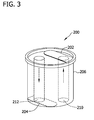
- Figure 3 illustrates an alternative embodiment of a dispenser insert 200 in which a first reed valve 202 and a second reed valve 204 are integrally formed as part of a plug 206.
- first reed valve 202, second reed valve 204 and plug 206 are formed as a single molded piece.
- First axial hole 210 and second axial hole 212 allow first reed valve 202 and second reed valve 204 to operate in the manner described above with respect to the embodiment of Figure 2 .
- one or more reed retainers similar to reed retainer 102 may be incorporated into the embodiment of Figure 3 .
- Figure 4 illustrates another alternative embodiment of a dispenser insert 300 in which a first reed valve 302 and a second reed valve 304 are attached to plug 306 utilizing a snap fit mechanism.
- first reed valve 302 incorporates a snap fit pin 312 which is inserted into a corresponding bore 314 or mating feature accessible from the top 316 of plug 306.
- the second reed valve 304 incorporates a snap fit pin 322 which is inserted into a corresponding bore 324 or mating feature accessible from the bottom 326 of plug 306.
- First axial hole 330 and second axial hole 332 allow first reed valve 302 and second reed valve 304 to operate in the manner described above with respect to the embodiment of Figure 2 .
- one or more reed retainers similar to reed retainer 102 may be incorporated into the embodiment of Figure 4 .
- Figure 5 is a flowchart 500 that illustrates a method for dispensing a fluid from a flexible dispenser.
- the method includes applying 502 a positive pressure to the dispenser 10 to force the fluid 12 through the first axial hole 60 formed in the plug 52 placed in an opening 17 of the dispenser 10, the pressure causing first reed valve 100 mounted on a side of the plug 52 opposite the fluid storage (e.g., on the top 56) to move away from the first axial hole 60 to allow the fluid 12 to pass through, the positive pressure further causing the second reed valve 110 on a bottom 130 of the plug 52, where the fluid 12 is contained, to maintain placement to substantially seal the second axial hole 62 formed in the plug 52.
- the method continues by releasing 504 the positive pressure to allow the first reed valve 100 to return to a position that substantially seals the first axial hole 60 and allows the second reed valve 110 to open thereby allowing air to enter the dispenser 10 through the second axial hole 62 until a difference in pressure between an interior and an exterior of the dispenser 10 is reduced to substantially zero.
- the difference in pressure is approximately zero, the second reed valve 110 is allowed 506 to substantially reseal the second axial hole 62.
- Other embodiments of the method include utilizing 504 a reed retainer 102 to place a positive pressure onto the first reed valve 100 with respect to the first axial hole 60.
- a fluid dispenser including a dispenser 10 including a flexible material, said dispenser 10 including a body portion 14 and a cylindrical mouth portion 16 extending from said body portion 14, said mouth portion 16 including an opening defining a lip 19 extending about said opening; a cap 20 operable to engage said mouth portion 16 of said dispenser 10, said cap 20 including an aperture therethrough operable to dispense a fluid stored within said dispenser 10; and a cylindrical insert 50 sized for placement within said opening between said mouth portion and said cap, said cylindrical insert 50 including: a substantially solid plug 52, 206, 306 including a first axial hole 60 therethrough and a second axial hole 62 therethrough; a first reed valve 100, 202, 302 operably attached to said plug 52, 206, 306 to close said first axial hole 60, 210, 310) from an outside of said dispenser 10; and a second reed valve 110, 204, 304 operably attached to said plug 52, 206, 306 to close said second axial hole 62
- said cylindrical insert 50 further includes a reed retainer attached thereto operable to place a positive pressure onto said first reed valve 100, 202, 302 with respect to said first axial hole 60, 210, 310.
- said reed retainer includes aluminum.
- the fluid dispenser further including a threaded fastener, said threaded fastener operable to pass through holes 120 in said first reed valve 100, 202, 302 and said reed retainer and threadably engage said plug 52, 206, 306 to maintain an orientation of said first reed valve 100, 202, 302 and said reed retainer.
- said first reed valve 100, 202, 302 and said second reed valve 110, 204, 304 comprise steel.
- said first reed valve 100, 202, 302 is operable to deflect away from said plug 52, 206, 306 when a positive pressure is placed on said dispenser 10 to allow a fluid to pass from said dispenser, through said first axial hole 60, 210, 310, and said aperture of said tip.
- said second reed valve 110, 204, 304 is operable to deflect away from said plug 52, 206, 306 when a negative pressure is placed on said dispenser 10 to allow a fluid to pass into said dispenser, through said aperture of said tip and said second axial hole.
- said substantially solid plug 52, 206, 306 includes a plastic.
- said first reed valve 100, 202, 302 and said second reed valve 110, 204, 304 comprise a steel of about 0.003 inch in thickness.
- first reed valve 302 and said second reed valve 304 each comprise a snap fit mechanism configured to engage a mating feature formed in said substantially solid plug 306.
- first reed valve 202, said second reed valve 204, and said substantially solid plug 206 are formed as a single molded piece.
- said substantially solid plug 52, 206, 306 includes a protrusion about a perimeter thereof operable for engaging the lip of said mouth portion 16.
- said substantially solid plug 52, 206, 306 includes a recessed area, said first reed valve 100, 202, 302 operably attached to said recessed area.
- first reed valve 100, 202, 302 includes a biasing force for closing said first axial hole 60, 210, 310 and said second reed valve 110, 204, 304 includes a biasing force for closing said second axial hole 62, 212, 332.
- an insert sized for placement within an opening of a dispenser 10, said cylindrical insert 50 including: a substantially solid plug 52, 206, 306 including a first surface, a second surface, a first axial hole 60, 210, 310 extending from said first surface to said second surface, and a second axial hole 62, 212, 332 extending from said first surface to said second surface; a first reed valve 100, 202, 302 operably attached to said first surface of said plug 52, 206, 306 to close said first axial hole 60, 210, 310; and a second reed valve 110, 204, 304 operably attached to said second surface of said plug 52, 206, 306 to close said second axial hole 62, 212, 332.
- an insert further including a reed retainer attached thereto operable to place a positive pressure onto said first reed valve 100, 202, 302 with respect to said first axial hole 60, 210, 310.
- said reed retainer includes aluminum
- said first reed valve 100, 202, 302 and said second reed valve 110, 204, 304 comprise steel
- said plug 52, 206, 306 includes plastic.
- first reed valve 100, 202, 302 is operable to deflect away from said first surface when a positive pressure, originating proximate said second surface, is applied through said first axial hole 60, 210, 310; and said second reed valve 110, 204, 304 is operable to deflect away from said second surface when a positive pressure, originating proximate said first surface, is applied through said second axial hole 62, 212, 332.
- a method for dispensing a fluid from a flexible dispenser 10 including: applying a positive pressure to the dispenser to force the fluid through a first axial hole 60, 210, 310 formed in a plug 52, 206, 306 placed in a opening of the dispenser 10, the pressure causing a first reed valve 100, 202, 302 mounted on a side of the plug 52, 206, 306 opposite the fluid storage to move away from the first axial hole 60, 210, 310 to allow the fluid to pass through, the positive pressure further causing a second reed valve 110, 204, 304 on a side of the plug 52, 206, 306 where the fluid is contained to maintain placement to substantially seal a second axial hole 62, 212, 332 formed in the plug 52, 206, 306; releasing the positive pressure to allow the first reed valve to return to a position that substantially seals the first axial hole 60, 210, 310 and allows the second reed valve 110, 204,
- an insert sized for placement within an opening of a dispenser are described in detail above.
- the above-described dispenser insert facilitates providing a substantially sealed chemical dispenser that would normally emit chemical vapors into the surrounding atmosphere when not in use.
- the dispenser cap insert described herein helps to ensure safe environmental conditions in areas where chemicals are stored and facilitates maintaining an area surround the dispenser that is free from harmful gases that may be emitted from the stored chemicals by enabling the dispenser to use atmospheric pressure to seal the dispenser when not in use. Also, the systems described herein will prevent leaking of should chemicals such the dispenser become overturned.
Landscapes
- Engineering & Computer Science (AREA)
- Mechanical Engineering (AREA)
- Containers And Packaging Bodies Having A Special Means To Remove Contents (AREA)
Applications Claiming Priority (1)
| Application Number | Priority Date | Filing Date | Title |
|---|---|---|---|
| US13/253,204 US8746511B2 (en) | 2011-10-05 | 2011-10-05 | Self-sealing dispenser insert and method for assembling the same |
Publications (2)
| Publication Number | Publication Date |
|---|---|
| EP2578320A1 true EP2578320A1 (de) | 2013-04-10 |
| EP2578320B1 EP2578320B1 (de) | 2014-12-10 |
Family
ID=46963580
Family Applications (1)
| Application Number | Title | Priority Date | Filing Date |
|---|---|---|---|
| EP20120186136 Active EP2578320B1 (de) | 2011-10-05 | 2012-09-26 | Selbstabdichtender Ausgabeeinsatz und Montierverfahren dafür |
Country Status (2)
| Country | Link |
|---|---|
| US (1) | US8746511B2 (de) |
| EP (1) | EP2578320B1 (de) |
Citations (3)
| Publication number | Priority date | Publication date | Assignee | Title |
|---|---|---|---|---|
| FR601494A (fr) * | 1925-05-27 | 1926-03-03 | Perfectionnements aux vaporisateurs pour parfums | |
| US4179051A (en) * | 1977-08-01 | 1979-12-18 | Ryder International Corporation | One-piece check valve for use in a fluid dispenser |
| WO2011075589A1 (en) * | 2009-12-16 | 2011-06-23 | Water Pik, Inc. | Squeeze bottle for sinus cavity rinse |
Family Cites Families (29)
| Publication number | Priority date | Publication date | Assignee | Title |
|---|---|---|---|---|
| FR601464A (fr) | 1924-10-08 | 1926-03-03 | Installation de réfrigération pour l'eau de refroidissement pour véhicules à vapeur travaillant avec condensation | |
| US1735784A (en) | 1928-05-11 | 1929-11-12 | Karl G Heed | Oil can |
| US3474936A (en) | 1967-05-29 | 1969-10-28 | John E Mcdonnell | Squeeze bottle dispenser |
| US4073294A (en) | 1975-07-23 | 1978-02-14 | Medical Development Corporation | Negative pressure drainage vessel |
| US4122979A (en) * | 1976-06-01 | 1978-10-31 | Laauwe Robert H | Squeeze bottle containing a liquid product and operative whether upright or inverted |
| US4420100A (en) * | 1978-10-31 | 1983-12-13 | Containaire, Inc. | Dispensing apparatus |
| US4286735A (en) | 1979-08-14 | 1981-09-01 | Sneider Vincent R | Squeeze dispenser with flexible conduit with attached, weighted and grooved end |
| US4340157A (en) | 1980-11-20 | 1982-07-20 | Becton, Dickinson & Company | Self-sealing closure dispenser for plastic stain bottles |
| US4557401A (en) | 1981-11-23 | 1985-12-10 | The Boeing Company | Fluid container safety valve |
| US4711378A (en) * | 1986-03-24 | 1987-12-08 | S. C. Johnson & Son, Inc. | Spray cap assembly comprising a base unit and push/pull closure means |
| US4828149A (en) * | 1987-03-19 | 1989-05-09 | Hester Kenneth D | Tiltable metering dispenser |
| US4964380A (en) * | 1989-05-24 | 1990-10-23 | Brunswick Corporation | Induction system for a two-cycle engine |
| US5079013A (en) | 1990-08-30 | 1992-01-07 | Belanger Richard A | Dripless liquid feeding/training containers |
| US5310112A (en) * | 1992-03-05 | 1994-05-10 | Philip Meshberg | Valved gasket for dispenser |
| DE4219857A1 (de) | 1992-06-17 | 1993-12-23 | Perfect Ventil Gmbh | Verformbarer Behälter zum Ausbringen von Flüssigkeit |
| US5979569A (en) * | 1993-09-21 | 1999-11-09 | Simulprobe Technologies, Inc. | Method and apparatus for environmental sampling |
| US5655686A (en) | 1995-05-30 | 1997-08-12 | Jermyn; Arthur Charles | Device for unidirectionally dispensing a hygienic cleaning liquid |
| US5919360A (en) * | 1996-08-07 | 1999-07-06 | Cuno, Inc. | Additive dispensing apparatus |
| US5873478A (en) * | 1997-01-13 | 1999-02-23 | Sullivan; Michael J. | Spill-proof cap for beverage containers |
| US5890620A (en) | 1997-08-14 | 1999-04-06 | Belcastro; Domenic | Automatically sealing cup |
| US6264452B1 (en) * | 1999-12-15 | 2001-07-24 | Scroll Technologies | Reinforcement pin for check valve |
| JP2002250233A (ja) * | 2001-02-22 | 2002-09-06 | Honda Motor Co Ltd | リードバルブ |
| US6561371B2 (en) | 2001-06-04 | 2003-05-13 | Impact Confections, Inc. | Self sealing cap |
| US7261221B2 (en) * | 2003-04-16 | 2007-08-28 | Innovation And Design, Inc. | Inverted dispensing system and apparatus |
| WO2005082214A1 (en) * | 2004-02-25 | 2005-09-09 | Andhow Innovations, Llc. | Leak resistant siphoning device for use in fluid transfer |
| US7395790B2 (en) * | 2004-11-18 | 2008-07-08 | S&S Cycle, Inc. | Reed valve breather for evolution engine |
| US7614422B2 (en) * | 2005-03-29 | 2009-11-10 | Moto Tassinari | Reed valve assembly |
| US7503317B2 (en) * | 2005-09-15 | 2009-03-17 | Kohler Co. | Internal breather for an internal combustion engine |
| US7828176B2 (en) * | 2006-05-15 | 2010-11-09 | Harper William A | Fluid dispenser with internal pump |
-
2011
- 2011-10-05 US US13/253,204 patent/US8746511B2/en active Active
-
2012
- 2012-09-26 EP EP20120186136 patent/EP2578320B1/de active Active
Patent Citations (3)
| Publication number | Priority date | Publication date | Assignee | Title |
|---|---|---|---|---|
| FR601494A (fr) * | 1925-05-27 | 1926-03-03 | Perfectionnements aux vaporisateurs pour parfums | |
| US4179051A (en) * | 1977-08-01 | 1979-12-18 | Ryder International Corporation | One-piece check valve for use in a fluid dispenser |
| WO2011075589A1 (en) * | 2009-12-16 | 2011-06-23 | Water Pik, Inc. | Squeeze bottle for sinus cavity rinse |
Also Published As
| Publication number | Publication date |
|---|---|
| US8746511B2 (en) | 2014-06-10 |
| US20130087574A1 (en) | 2013-04-11 |
| EP2578320B1 (de) | 2014-12-10 |
Similar Documents
| Publication | Publication Date | Title |
|---|---|---|
| US10259624B2 (en) | Cap | |
| EP2822699B1 (de) | Spritzpistole mit internem boost-kanal | |
| RU2385774C2 (ru) | Емкость для хранения капельно дозируемой жидкости, обратимо деформируемая в результате всасывания воздуха | |
| JP5538057B2 (ja) | 吐出容器 | |
| US9199783B2 (en) | Plastic valves and methods of using the same | |
| EP3144243B1 (de) | Kappe | |
| EP1454839A2 (de) | Lösungsmittelflasche versehen mit einer verstellbaren Abgabedüse | |
| US20100213220A1 (en) | Closed loop dispensing system including an improved throat plug assembly | |
| CN101970128A (zh) | 瓶和用于容器的阀配件 | |
| EP1486429A3 (de) | Verschluss mit Belüftung | |
| US20120118416A1 (en) | Adaptor for use with a valve fitment | |
| US9670049B2 (en) | Plastic beer keg | |
| US20150314031A1 (en) | Dispenser For Air Freshener Containers | |
| US11390433B2 (en) | Container | |
| CN105916591B (zh) | 流体贮存器及包括该贮存器的分配器 | |
| JP2014028642A (ja) | 注出キャップ及びそれを有する容器 | |
| CA2939212C (en) | A single hole single action aerosol can | |
| US20190031490A1 (en) | Front Push Tap | |
| US20100044375A1 (en) | Self-sealing dispenser cap and method for assembling the same | |
| US20160145012A1 (en) | Oil Dispensing Lid | |
| US10646887B2 (en) | Dispensing member and dispenser comprising such a member | |
| US8746511B2 (en) | Self-sealing dispenser insert and method for assembling the same | |
| US10293990B2 (en) | Closure system and container having a closure system | |
| JP2017013811A (ja) | 吐出容器 | |
| JP6482572B2 (ja) | 液体分配装置 |
Legal Events
| Date | Code | Title | Description |
|---|---|---|---|
| PUAI | Public reference made under article 153(3) epc to a published international application that has entered the european phase |
Free format text: ORIGINAL CODE: 0009012 |
|
| 17P | Request for examination filed |
Effective date: 20120926 |
|
| AK | Designated contracting states |
Kind code of ref document: A1 Designated state(s): AL AT BE BG CH CY CZ DE DK EE ES FI FR GB GR HR HU IE IS IT LI LT LU LV MC MK MT NL NO PL PT RO RS SE SI SK SM TR |
|
| AX | Request for extension of the european patent |
Extension state: BA ME |
|
| GRAP | Despatch of communication of intention to grant a patent |
Free format text: ORIGINAL CODE: EPIDOSNIGR1 |
|
| INTG | Intention to grant announced |
Effective date: 20140210 |
|
| GRAP | Despatch of communication of intention to grant a patent |
Free format text: ORIGINAL CODE: EPIDOSNIGR1 |
|
| INTG | Intention to grant announced |
Effective date: 20140703 |
|
| GRAS | Grant fee paid |
Free format text: ORIGINAL CODE: EPIDOSNIGR3 |
|
| GRAA | (expected) grant |
Free format text: ORIGINAL CODE: 0009210 |
|
| AK | Designated contracting states |
Kind code of ref document: B1 Designated state(s): AL AT BE BG CH CY CZ DE DK EE ES FI FR GB GR HR HU IE IS IT LI LT LU LV MC MK MT NL NO PL PT RO RS SE SI SK SM TR |
|
| REG | Reference to a national code |
Ref country code: GB Ref legal event code: FG4D |
|
| REG | Reference to a national code |
Ref country code: CH Ref legal event code: EP |
|
| REG | Reference to a national code |
Ref country code: IE Ref legal event code: FG4D |
|
| REG | Reference to a national code |
Ref country code: AT Ref legal event code: REF Ref document number: 700383 Country of ref document: AT Kind code of ref document: T Effective date: 20150115 |
|
| REG | Reference to a national code |
Ref country code: DE Ref legal event code: R096 Ref document number: 602012004209 Country of ref document: DE Effective date: 20150122 |
|
| REG | Reference to a national code |
Ref country code: AT Ref legal event code: MK05 Ref document number: 700383 Country of ref document: AT Kind code of ref document: T Effective date: 20141210 Ref country code: NL Ref legal event code: VDEP Effective date: 20141210 |
|
| REG | Reference to a national code |
Ref country code: NL Ref legal event code: VDEP Effective date: 20141210 |
|
| PG25 | Lapsed in a contracting state [announced via postgrant information from national office to epo] |
Ref country code: LT Free format text: LAPSE BECAUSE OF FAILURE TO SUBMIT A TRANSLATION OF THE DESCRIPTION OR TO PAY THE FEE WITHIN THE PRESCRIBED TIME-LIMIT Effective date: 20141210 Ref country code: ES Free format text: LAPSE BECAUSE OF FAILURE TO SUBMIT A TRANSLATION OF THE DESCRIPTION OR TO PAY THE FEE WITHIN THE PRESCRIBED TIME-LIMIT Effective date: 20141210 Ref country code: FI Free format text: LAPSE BECAUSE OF FAILURE TO SUBMIT A TRANSLATION OF THE DESCRIPTION OR TO PAY THE FEE WITHIN THE PRESCRIBED TIME-LIMIT Effective date: 20141210 Ref country code: NO Free format text: LAPSE BECAUSE OF FAILURE TO SUBMIT A TRANSLATION OF THE DESCRIPTION OR TO PAY THE FEE WITHIN THE PRESCRIBED TIME-LIMIT Effective date: 20150310 |
|
| REG | Reference to a national code |
Ref country code: LT Ref legal event code: MG4D |
|
| PG25 | Lapsed in a contracting state [announced via postgrant information from national office to epo] |
Ref country code: HR Free format text: LAPSE BECAUSE OF FAILURE TO SUBMIT A TRANSLATION OF THE DESCRIPTION OR TO PAY THE FEE WITHIN THE PRESCRIBED TIME-LIMIT Effective date: 20141210 Ref country code: RS Free format text: LAPSE BECAUSE OF FAILURE TO SUBMIT A TRANSLATION OF THE DESCRIPTION OR TO PAY THE FEE WITHIN THE PRESCRIBED TIME-LIMIT Effective date: 20141210 Ref country code: LV Free format text: LAPSE BECAUSE OF FAILURE TO SUBMIT A TRANSLATION OF THE DESCRIPTION OR TO PAY THE FEE WITHIN THE PRESCRIBED TIME-LIMIT Effective date: 20141210 Ref country code: AT Free format text: LAPSE BECAUSE OF FAILURE TO SUBMIT A TRANSLATION OF THE DESCRIPTION OR TO PAY THE FEE WITHIN THE PRESCRIBED TIME-LIMIT Effective date: 20141210 Ref country code: GR Free format text: LAPSE BECAUSE OF FAILURE TO SUBMIT A TRANSLATION OF THE DESCRIPTION OR TO PAY THE FEE WITHIN THE PRESCRIBED TIME-LIMIT Effective date: 20150311 Ref country code: SE Free format text: LAPSE BECAUSE OF FAILURE TO SUBMIT A TRANSLATION OF THE DESCRIPTION OR TO PAY THE FEE WITHIN THE PRESCRIBED TIME-LIMIT Effective date: 20141210 |
|
| PG25 | Lapsed in a contracting state [announced via postgrant information from national office to epo] |
Ref country code: NL Free format text: LAPSE BECAUSE OF FAILURE TO SUBMIT A TRANSLATION OF THE DESCRIPTION OR TO PAY THE FEE WITHIN THE PRESCRIBED TIME-LIMIT Effective date: 20141210 |
|
| PG25 | Lapsed in a contracting state [announced via postgrant information from national office to epo] |
Ref country code: RO Free format text: LAPSE BECAUSE OF FAILURE TO SUBMIT A TRANSLATION OF THE DESCRIPTION OR TO PAY THE FEE WITHIN THE PRESCRIBED TIME-LIMIT Effective date: 20141210 Ref country code: EE Free format text: LAPSE BECAUSE OF FAILURE TO SUBMIT A TRANSLATION OF THE DESCRIPTION OR TO PAY THE FEE WITHIN THE PRESCRIBED TIME-LIMIT Effective date: 20141210 Ref country code: SK Free format text: LAPSE BECAUSE OF FAILURE TO SUBMIT A TRANSLATION OF THE DESCRIPTION OR TO PAY THE FEE WITHIN THE PRESCRIBED TIME-LIMIT Effective date: 20141210 Ref country code: PT Free format text: LAPSE BECAUSE OF FAILURE TO SUBMIT A TRANSLATION OF THE DESCRIPTION OR TO PAY THE FEE WITHIN THE PRESCRIBED TIME-LIMIT Effective date: 20150410 Ref country code: CZ Free format text: LAPSE BECAUSE OF FAILURE TO SUBMIT A TRANSLATION OF THE DESCRIPTION OR TO PAY THE FEE WITHIN THE PRESCRIBED TIME-LIMIT Effective date: 20141210 |
|
| PG25 | Lapsed in a contracting state [announced via postgrant information from national office to epo] |
Ref country code: PL Free format text: LAPSE BECAUSE OF FAILURE TO SUBMIT A TRANSLATION OF THE DESCRIPTION OR TO PAY THE FEE WITHIN THE PRESCRIBED TIME-LIMIT Effective date: 20141210 Ref country code: IS Free format text: LAPSE BECAUSE OF FAILURE TO SUBMIT A TRANSLATION OF THE DESCRIPTION OR TO PAY THE FEE WITHIN THE PRESCRIBED TIME-LIMIT Effective date: 20150410 |
|
| REG | Reference to a national code |
Ref country code: DE Ref legal event code: R097 Ref document number: 602012004209 Country of ref document: DE |
|
| PLBE | No opposition filed within time limit |
Free format text: ORIGINAL CODE: 0009261 |
|
| STAA | Information on the status of an ep patent application or granted ep patent |
Free format text: STATUS: NO OPPOSITION FILED WITHIN TIME LIMIT |
|
| PG25 | Lapsed in a contracting state [announced via postgrant information from national office to epo] |
Ref country code: DK Free format text: LAPSE BECAUSE OF FAILURE TO SUBMIT A TRANSLATION OF THE DESCRIPTION OR TO PAY THE FEE WITHIN THE PRESCRIBED TIME-LIMIT Effective date: 20141210 |
|
| 26N | No opposition filed |
Effective date: 20150911 |
|
| PG25 | Lapsed in a contracting state [announced via postgrant information from national office to epo] |
Ref country code: IT Free format text: LAPSE BECAUSE OF FAILURE TO SUBMIT A TRANSLATION OF THE DESCRIPTION OR TO PAY THE FEE WITHIN THE PRESCRIBED TIME-LIMIT Effective date: 20141210 |
|
| PG25 | Lapsed in a contracting state [announced via postgrant information from national office to epo] |
Ref country code: SI Free format text: LAPSE BECAUSE OF FAILURE TO SUBMIT A TRANSLATION OF THE DESCRIPTION OR TO PAY THE FEE WITHIN THE PRESCRIBED TIME-LIMIT Effective date: 20141210 |
|
| PG25 | Lapsed in a contracting state [announced via postgrant information from national office to epo] |
Ref country code: LU Free format text: LAPSE BECAUSE OF FAILURE TO SUBMIT A TRANSLATION OF THE DESCRIPTION OR TO PAY THE FEE WITHIN THE PRESCRIBED TIME-LIMIT Effective date: 20150926 Ref country code: MC Free format text: LAPSE BECAUSE OF FAILURE TO SUBMIT A TRANSLATION OF THE DESCRIPTION OR TO PAY THE FEE WITHIN THE PRESCRIBED TIME-LIMIT Effective date: 20141210 |
|
| REG | Reference to a national code |
Ref country code: CH Ref legal event code: PL |
|
| PG25 | Lapsed in a contracting state [announced via postgrant information from national office to epo] |
Ref country code: BE Free format text: LAPSE BECAUSE OF FAILURE TO SUBMIT A TRANSLATION OF THE DESCRIPTION OR TO PAY THE FEE WITHIN THE PRESCRIBED TIME-LIMIT Effective date: 20141210 |
|
| REG | Reference to a national code |
Ref country code: IE Ref legal event code: MM4A |
|
| PG25 | Lapsed in a contracting state [announced via postgrant information from national office to epo] |
Ref country code: LI Free format text: LAPSE BECAUSE OF NON-PAYMENT OF DUE FEES Effective date: 20150930 Ref country code: IE Free format text: LAPSE BECAUSE OF NON-PAYMENT OF DUE FEES Effective date: 20150926 Ref country code: CH Free format text: LAPSE BECAUSE OF NON-PAYMENT OF DUE FEES Effective date: 20150930 |
|
| REG | Reference to a national code |
Ref country code: FR Ref legal event code: PLFP Year of fee payment: 5 |
|
| PG25 | Lapsed in a contracting state [announced via postgrant information from national office to epo] |
Ref country code: MT Free format text: LAPSE BECAUSE OF FAILURE TO SUBMIT A TRANSLATION OF THE DESCRIPTION OR TO PAY THE FEE WITHIN THE PRESCRIBED TIME-LIMIT Effective date: 20141210 |
|
| PG25 | Lapsed in a contracting state [announced via postgrant information from national office to epo] |
Ref country code: BG Free format text: LAPSE BECAUSE OF FAILURE TO SUBMIT A TRANSLATION OF THE DESCRIPTION OR TO PAY THE FEE WITHIN THE PRESCRIBED TIME-LIMIT Effective date: 20141210 Ref country code: HU Free format text: LAPSE BECAUSE OF FAILURE TO SUBMIT A TRANSLATION OF THE DESCRIPTION OR TO PAY THE FEE WITHIN THE PRESCRIBED TIME-LIMIT; INVALID AB INITIO Effective date: 20120926 Ref country code: SM Free format text: LAPSE BECAUSE OF FAILURE TO SUBMIT A TRANSLATION OF THE DESCRIPTION OR TO PAY THE FEE WITHIN THE PRESCRIBED TIME-LIMIT Effective date: 20141210 |
|
| PG25 | Lapsed in a contracting state [announced via postgrant information from national office to epo] |
Ref country code: CY Free format text: LAPSE BECAUSE OF FAILURE TO SUBMIT A TRANSLATION OF THE DESCRIPTION OR TO PAY THE FEE WITHIN THE PRESCRIBED TIME-LIMIT Effective date: 20141210 |
|
| PG25 | Lapsed in a contracting state [announced via postgrant information from national office to epo] |
Ref country code: TR Free format text: LAPSE BECAUSE OF FAILURE TO SUBMIT A TRANSLATION OF THE DESCRIPTION OR TO PAY THE FEE WITHIN THE PRESCRIBED TIME-LIMIT Effective date: 20141210 |
|
| REG | Reference to a national code |
Ref country code: FR Ref legal event code: PLFP Year of fee payment: 6 |
|
| PG25 | Lapsed in a contracting state [announced via postgrant information from national office to epo] |
Ref country code: MK Free format text: LAPSE BECAUSE OF FAILURE TO SUBMIT A TRANSLATION OF THE DESCRIPTION OR TO PAY THE FEE WITHIN THE PRESCRIBED TIME-LIMIT Effective date: 20141210 |
|
| REG | Reference to a national code |
Ref country code: FR Ref legal event code: PLFP Year of fee payment: 7 |
|
| PG25 | Lapsed in a contracting state [announced via postgrant information from national office to epo] |
Ref country code: AL Free format text: LAPSE BECAUSE OF FAILURE TO SUBMIT A TRANSLATION OF THE DESCRIPTION OR TO PAY THE FEE WITHIN THE PRESCRIBED TIME-LIMIT Effective date: 20141210 |
|
| P01 | Opt-out of the competence of the unified patent court (upc) registered |
Effective date: 20230516 |
|
| PGFP | Annual fee paid to national office [announced via postgrant information from national office to epo] |
Ref country code: DE Payment date: 20250929 Year of fee payment: 14 |
|
| PGFP | Annual fee paid to national office [announced via postgrant information from national office to epo] |
Ref country code: GB Payment date: 20250929 Year of fee payment: 14 |
|
| PGFP | Annual fee paid to national office [announced via postgrant information from national office to epo] |
Ref country code: FR Payment date: 20250925 Year of fee payment: 14 |