EP2578367A1 - Über kabel gesteuerte positionierungsvorrichtung - Google Patents
Über kabel gesteuerte positionierungsvorrichtung Download PDFInfo
- Publication number
- EP2578367A1 EP2578367A1 EP10734765.0A EP10734765A EP2578367A1 EP 2578367 A1 EP2578367 A1 EP 2578367A1 EP 10734765 A EP10734765 A EP 10734765A EP 2578367 A1 EP2578367 A1 EP 2578367A1
- Authority
- EP
- European Patent Office
- Prior art keywords
- cable
- cables
- work surface
- platform
- spindle
- Prior art date
- Legal status (The legal status is an assumption and is not a legal conclusion. Google has not performed a legal analysis and makes no representation as to the accuracy of the status listed.)
- Granted
Links
Images



Classifications
-
- B—PERFORMING OPERATIONS; TRANSPORTING
- B25—HAND TOOLS; PORTABLE POWER-DRIVEN TOOLS; MANIPULATORS
- B25J—MANIPULATORS; CHAMBERS PROVIDED WITH MANIPULATION DEVICES
- B25J17/00—Joints
- B25J17/02—Wrist joints
- B25J17/0258—Two-dimensional joints
- B25J17/0266—Two-dimensional joints comprising more than two actuating or connecting rods
-
- B—PERFORMING OPERATIONS; TRANSPORTING
- B25—HAND TOOLS; PORTABLE POWER-DRIVEN TOOLS; MANIPULATORS
- B25J—MANIPULATORS; CHAMBERS PROVIDED WITH MANIPULATION DEVICES
- B25J9/00—Program-controlled manipulators
- B25J9/003—Program-controlled manipulators having parallel kinematics
- B25J9/0078—Program-controlled manipulators having parallel kinematics actuated by cables
Definitions
- the present invention is comprised in the technical field of robotic devices which allow the positioning of actuators, manipulators, implements, tools, etc. for the activities of production, manipulation, modification, inspection, etc., on a work surface or the medium which surrounds it.
- the fact that the cables do not work under compression means that the resulting work space is not so evident, requires a more detailed study and it is not always possible to reach a determined position and orientation of the element controlled by the cables.
- the set of valid points in a cable kinematics will depend on the number of cables and on their geometric arrangement. Valid points are understood as those which allow controlling all the degrees of freedom of the mechanism without the cables starting to work under compression.
- the cables have problems of interfering with one another and the surrounding medium, so it is necessary to verify said interferences and check them throughout the work space.
- document CN-101554892 proposes a ventilator which is used to maintain a mobile platform positioned above the surface.
- the stability provided by the effect of such ventilator is not as effective as desired in applications that are more demanding from the viewpoint of vibrations and stresses (drilling, polishing, cutting, painting, etc.), and the existence of the ventilator also involves the presence of an additional element to be controlled.
- the object of the present invention is to overcome the drawbacks of the state of the art explained above by means of a positioning device controlled by cables comprising four cables connected at their respective first ends in respective anchoring mechanisms of a platform and at their respective second ends in respective cable gathering and release mechanisms (which can be arranged in diagonally opposing pairs) and driven by respective motors for displacing the platform with respect to a work surface by means of the controlled release and gathering of the cables, which is characterized in that the platform has a support base provided with means for sliding over the work surface (for example, by means of rolling elements or elements for sliding without contact by means of creating magnetic fields); at least one of the cables extends obliquely between a first plane parallel to the work surface in which the cable gathering and release mechanism is arranged and a second plane parallel to the work surface in which the anchoring mechanism is located such that the tractive force exerted in the mentioned cables by the cable release and gathering mechanisms has a resultant, with a component perpendicular to the work surface which pushes the support base of the platform against the
- each anchoring mechanism is located at a distance from the support base provided with rolling elements of the platform, such that each cable extends obliquely with respect to the work surface between the anchoring mechanism and the cable gathering and release mechanism to which it is connected. Furthermore, each anchoring mechanism can rotate perpendicularly and parallel with respect to the support base and can be a cardan shaft.
- the anchoring mechanisms comprise a first pair of anchoring mechanisms arranged in a first row and connected to respective cables of a first pair of cables, and a second pair of anchoring mechanisms arranged in a second row and connected to respective cables of a second pair of cables, such that each cable connected to an anchoring mechanism of said first row intersects with a cable connected to an anchoring mechanism of said second row, such that the traction of the cables by the respective cable gathering and release mechanisms forces the support base of the platform against the work surface.
- the present invention is useful as a robotic platform with parallel kinematics controlled by means of cables and through the support on the work surface.
- the platform is displaced, maintaining its equilibrium at all times on said support surface by varying the lengths and the tensions of the cables. Since the length of each of the four cables can vary, such cables are wound or released as appropriate.
- the platform can be prepared to perform any type of operation on the surface. To that end, it may be necessary to increase the tension of the cables for the purpose of increasing the resultant component against the work surface and increasing the rigidity of the mechanism.
- the platform has enough space therein for assembling an additional actuator or manipulator on it (not shown in the drawings attached to the present specification) which is in charge of performing any type of activity of production, manipulation, modification, inspection, etc., on the work surface or the medium which surrounds it.
- additional robotic arm or actuator can be controlled by means of an umbilical cable or even by using the cables for displacing the platform. Therefore, the present invention enables performing automated operations on a determined work surface or the surrounding medium thereof by covering a work space that is much larger than the typical work spaces at a very low cost and with high dynamic capacity.
- the anchoring mechanisms of the first row of said support base are preferably located perpendicularly at a greater distance than the anchoring mechanisms of the second row.
- the platform comprises a lower base comprising the support base and an upper base in which the anchoring mechanisms are arranged; and connection means for attaching the lower base with the upper base.
- the upper platform can have a larger contour than the lower platform.
- each cable gathering and release mechanism can comprise an orienting device, a spindle device and a cable storage device.
- the cable storage device comprises a drum for winding and unwinding the cable by rotating about a drum axle
- the spindle device comprises a carriage which moves linearly along a spindle axle guiding the cable so that it moves forward to a distance corresponding to the width of a spiral of the drum when the cable is gradually wound on or unwound from the drum.
- the orienting device orients the cable towards the spindle device and comprises a pair of input rollers between which the cable moves towards the platform. The input rollers are assembled in a rotating arm which rotates according to the position of the cable.
- the orienting device, the spindle device and the cable storage device can be assembled in a common support base.
- the drum axle and the spindle axle are parallel and the drum is connected to the motor, for example through a reduction gear.
- the axle of the drum and the spindle axle are provided with respective gears arranged such that the axle of the drum confers rotational movement to the spindle, whereas the orienting device comprises a larger pulley which rotates about a shaft perpendicular to the spindle axle and redirects the cable towards the spindle device parallel to the spindle axle.
- This larger pulley can be arranged in a side arm connecting the carriage with the sliding body.
- the spindle device comprises an auxiliary linear guide parallel to the spindle axle
- the carriage comprises a sliding body which slides over the auxiliary linear guide when the carriage moves forward on the spindle axle, and a guide pulley which directs the cable perpendicularly towards the axle of the drum.
- the rotating arm and the larger pulley can be assembled in respective passive rotating shafts of a passive rotating mechanism which allows the rotation of the rotating arm and of the larger pulley in a shaft coaxial with the spindle axle.
- the passive rotating mechanism can be connected to a rotary encoder which determines the rotation of the rotating arm and of the larger pulley in said coaxial shaft.
- the rotating arm of the orienting device can also be connected to a rotating shaft transmitting its rotational movements to another rotary encoder.
- the cable release and gathering mechanisms can be assembled in an auxiliary structure surrounding at least part of the work surface.
- the positioning device controlled by cables according to the invention provides greater stability than the devices of the state of the art and a capacity of withstanding external excitations (especially in the direction perpendicular to the work surface) controlled at all times by means of the tension of the cable, and therefore greater capacity and stability when performing all types of operations than that which is provided by a ventilation jet.
- the present invention has the capacity to perform diverse mechanical operations that are much more demanding from the viewpoint of vibrations and stresses (drilling, polishing, cutting, painting, etc.) while the mobile platform remains stationary solely as a result of the tension of the cables and their arrangement.
- the present invention also maximizes the work space available between the cable gathering and release elements, and considers a reduction both in the number of motors and in the associated support structure when performing jobs on work surfaces or in media close to the work surface, significantly reducing its cost and the complexity of the control since the number of actuators is reduced. Furthermore, the spatial structures of cables do not interfere on the work surface or in the work space. Finally, the simplicity of the present invention with respect to the state of the art allows greater modularity and portability since it does not necessarily need a support structure for the operations.
- the rotary encoders of the passive cable following mechanisms provide redundant information about the orientation of each of the cables and, therefore, the position of the platform.
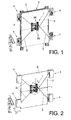
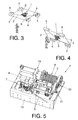
- the positioning platform -1- the degrees of freedom of which are completely controlled.
- the platform -1- is permanently supported on a fixed surface -2-, referred to as work surface, and is controlled through an assembly of cables -3-.
- the first end of each cable of said assembly -3- is attached to a cable gathering and release mechanism -4- which controls the length and tension of the corresponding cable -3- and which remains fixed on an auxiliary structure -5- although it can be alternatively or complementarily immobilized in the same work surface -2- or in a bearing structure of the work surface -2-.
- the other end of each cable -3- is anchored to the positioning platform -1- for pulling on same.
- the arrangement of the cables -3- maintains the platform -1-, regardless of the orientation of the work surface -2-, supported against the work surface -2- and in equilibrium with any external or internal excitation.
- the length of each cable -3- is controlled through the operation of the cable gathering and release mechanism -4-, which allows displacing the platform -1- along the entire work surface -2- in a controlled manner and precisely positioning it.
- the platform -1- is completely controlled.
- the assembly of the cables -3- and the work surface -2- restrict three degrees of freedom of the platform: two rotations and one displacement, and they allow controlling the rotation on the shaft perpendicular to the surface, as well as two displacements ( Figure 2 ).
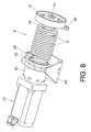
- the cable gathering and release mechanism -4- is assembled on a base -13- and basically consists of an orienting device -7- for the inlet of the cable -3-, a spindle device -8- assuring the orderly winding of the cable, a storage device -9- for the storage of the cable -3- and a servomotor -10-.
- the spindle device -8- and the storage device -9- are provided with respective gears -11-, -12- which are in charge of transmitting the rotational movement of the drum -28- driven by a servomotor -10-, into a forward movement of the spindle -24- so that the latter guides the cable into the corresponding groove of the drum -28- in an orderly manner.
- the orienting device ( Figure 6 ) comprises two input pulleys -14- between which the cable -3- moves and the function of which is to passively follow the cable -3-.
- Each cable -3- will vary its length according to the position of the platform -1- that is ordered, which means that each cable -3- of the cable device is oriented in a corresponding manner, as if it was a vector in spherical coordinates, r, ⁇ and ⁇ .
- the input pulleys -14- transmit the movement of the respective cable -3-through an arm -15- to the shaft -16- which rotates in the coordinate ⁇ .
- This rotation is collected by the first rotary encoder -17- and corresponds to coordinate ⁇ ( Figure 13 ).
- the cable -3- is again led through a larger pulley -18- which redirects it towards the spindle device -8-.
- the larger pulley -18- is connected to a passive rotating mechanism -19- which also follows the cable -3-, obtaining the angle ⁇ .
- the passive rotating mechanism -19- comprises two shafts -20- supported in respective supports -21-, and their rotation ( Figure 12 ) is collected by the second rotary encoder -22-.
- the coordinate r will be measured with the rotary encoder of the motor. Actually, it is only necessary to know the length of released cable, r. The mentioned angular coordinates will be used as redundant measurements and for the initial calibration of the mechanism.
- the cable -3- is again led to the spindle device -8- ( Figure 7 ) comprising two facing supports -23- in which a spindle -24- and an auxiliary linear guide -26- are assembled.
- the spindle axle -24- receives part of the torque through the gear (11) which, according to what has been indicated above, meshes with gear -12- of the storage device -9-.
- a carriage -25- is assembled in the spindle -24-, which carriage moves longitudinally as the spindle -24- rotates and is connected to the auxiliary linear guide -26- by means of a side arm -25a- connected to a sliding body -25b- which runs longitudinally in the auxiliary linear guide -26-.
- a guide pulley -27- is provided in the side arm -25a- of the carriage -25- which tangentially orients the incoming cable -3- longitudinally in the spindle device -8- from the orienting device -7- towards the drum -28- of the storage device -9- of the cable -3-.
- the ratio between the gears -11, 12- is designed such that the passage of the spindle -28- is such that the carriage -25- moves forward, driving the guide pulley -27- with it such that for each turn of the drum -28- of the storage device -9-, the guide pulley -27- moves forward to a distance corresponding to the width of a spiral of the drum -28-. It is thus assured that the cable -3- is gathered up in an orderly manner without stacking up on itself.
- the end of the axle of the drum -28- to which the gear -12- is connected is supported in a first support -30-.
- the opposite end of the axle of the drum -28- is connected to a servomotor -10- through a reduction gear -32- forming an assembly which is supported in the support -33-.
- the end of the cable -3- is anchored to the restraint -29-, such that with the rotation of the drum -28- in one direction or the other, the cable -3-, oriented by the guide pulley -27- of the spindle device -8-, is gradually wound on or unwound from the spirals of the drum -28-.
- the platform -1- shown in Figures 9 and 10 comprises a lower base -35- formed by a series of structural aluminum profiles provided in the areas of its corners with rolling elements -6-, such as in the form of balls, for example, which allow the platform -1- to roll freely over the work surface -2-, and an upper base -34- in which four cardan shafts -36- are arranged, to each of which the end of one of the cables -3- is respectively anchored, the opposite end of which is anchored to the restraint -29- of the drum device -9- of the corresponding cable gathering mechanism -4-.
- the upper base -34- and the lower base -35- are attached to one another by means of attachment columns -37-.
- the function of the cardan shafts -36- is to allow the cables -3- to be able to rotate both in the plane of the upper base -34- and in the plane perpendicular to the upper base -34-, such that they allow the respective cables to pull on the platform -1- and at the same time allow the platform -1- to be freely oriented.
- the cardan shafts also prevent wear that could occur with other types of attachments.
Landscapes
- Engineering & Computer Science (AREA)
- Robotics (AREA)
- Mechanical Engineering (AREA)
- Manipulator (AREA)
- Transmission Devices (AREA)
Applications Claiming Priority (1)
| Application Number | Priority Date | Filing Date | Title |
|---|---|---|---|
| PCT/ES2010/070355 WO2011148004A1 (es) | 2010-05-27 | 2010-05-27 | Dispositivo de posicionamiento controlado por cables |
Publications (2)
| Publication Number | Publication Date |
|---|---|
| EP2578367A1 true EP2578367A1 (de) | 2013-04-10 |
| EP2578367B1 EP2578367B1 (de) | 2014-04-09 |
Family
ID=43480924
Family Applications (1)
| Application Number | Title | Priority Date | Filing Date |
|---|---|---|---|
| EP10734765.0A Not-in-force EP2578367B1 (de) | 2010-05-27 | 2010-05-27 | Dispositivo de posicionamiento controlado por cables |
Country Status (4)
| Country | Link |
|---|---|
| EP (1) | EP2578367B1 (de) |
| CN (1) | CN103038029A (de) |
| ES (1) | ES2484095T3 (de) |
| WO (1) | WO2011148004A1 (de) |
Cited By (6)
| Publication number | Priority date | Publication date | Assignee | Title |
|---|---|---|---|---|
| WO2014172169A1 (en) * | 2013-04-19 | 2014-10-23 | Szarzynski Randall Lee | Multi-dimensional positioning of an object |
| US20140331808A1 (en) * | 2011-10-26 | 2014-11-13 | Core Pd Limited | Robotic apparatus and associated method |
| NL1040526C2 (en) * | 2013-12-03 | 2015-06-04 | Scrobby Robotics B V | Tethered autonomous solar panel installation cleaning device. |
| WO2015119323A1 (ko) * | 2014-02-04 | 2015-08-13 | 전남대학교산학협력단 | 케이블 기반 병렬형 로봇을 위한 케이블 연결 위치 변경장치 |
| WO2016096057A1 (en) * | 2014-12-19 | 2016-06-23 | Fundación Tecnalia Research & Innovation | Planar motion device |
| WO2017042729A1 (en) * | 2016-06-24 | 2017-03-16 | Universidad Tecnológica De Panamá | Wall-painting machine |
Families Citing this family (9)
| Publication number | Priority date | Publication date | Assignee | Title |
|---|---|---|---|---|
| NL2009478C2 (en) | 2012-09-17 | 2014-03-18 | Spanjer Stefan | System for moving a mobile tendon controlled platform robot. |
| DE102016107514A1 (de) * | 2016-04-22 | 2017-10-26 | Airbus Operations Gmbh | Bearbeitungsvorrichtung und Verfahren zum Betreiben einer Bearbeitungsvorrichtung |
| DE102016109402A1 (de) | 2016-05-23 | 2017-11-23 | Anton Jäger | Vorrichtung zum Reinigen von Flächen |
| CN107323558A (zh) * | 2017-08-16 | 2017-11-07 | 潘长偌 | 一种磁吸式爬墙打钉装置 |
| FR3098432B1 (fr) * | 2019-07-08 | 2021-06-11 | Univ Sorbonne | Module robotique de traction |
| IT201900016772A1 (it) * | 2019-09-19 | 2021-03-19 | Springa S R L | Apparato di localizzazione per macchina utensile |
| IT202100002558A1 (it) * | 2021-02-05 | 2022-08-05 | Marchesini Group Spa | Robot azionato a cavi |
| US12163616B2 (en) | 2022-01-10 | 2024-12-10 | Ge Infrastructure Technology Llc | Maintenance systems and methods including tether and support apparatus |
| CN115625658B (zh) * | 2022-09-23 | 2025-07-01 | 亿和精密工业(威海)有限公司 | 一种滚轮及托板组装自动定位装置 |
Family Cites Families (9)
| Publication number | Priority date | Publication date | Assignee | Title |
|---|---|---|---|---|
| JPS62117653A (ja) * | 1985-11-19 | 1987-05-29 | Fujita Corp | 外壁面自動走行装置 |
| JP2646008B2 (ja) | 1988-07-15 | 1997-08-25 | 日本ビソー株式会社 | 壁面作業用ロボット |
| US4932210A (en) | 1988-08-19 | 1990-06-12 | The Boeing Company | Shape memory metal precision actuator |
| US5585707A (en) * | 1994-02-28 | 1996-12-17 | Mcdonnell Douglas Corporation | Tendon suspended platform robot |
| JP3600905B2 (ja) | 1994-10-19 | 2004-12-15 | 東急建設株式会社 | 壁面描画ロボットシステム |
| DE10359273A1 (de) * | 2003-12-17 | 2005-07-21 | Erich Thallner | Justiervorrichtung |
| US7753642B2 (en) * | 2007-09-06 | 2010-07-13 | Ohio University | Apparatus and method associated with cable robot system |
| CN101554892B (zh) | 2009-05-08 | 2012-04-04 | 昆山市工业技术研究院有限责任公司 | 应用于高大建筑物立面清洗的壁面移动机器人 |
| CN101602209B (zh) | 2009-07-09 | 2011-06-22 | 北京航空航天大学 | 可重构式柔索驱动并联机器人及其驱动装置 |
-
2010
- 2010-05-27 ES ES10734765.0T patent/ES2484095T3/es active Active
- 2010-05-27 WO PCT/ES2010/070355 patent/WO2011148004A1/es not_active Ceased
- 2010-05-27 CN CN2010800672916A patent/CN103038029A/zh active Pending
- 2010-05-27 EP EP10734765.0A patent/EP2578367B1/de not_active Not-in-force
Non-Patent Citations (1)
| Title |
|---|
| See references of WO2011148004A1 * |
Cited By (9)
| Publication number | Priority date | Publication date | Assignee | Title |
|---|---|---|---|---|
| US20140331808A1 (en) * | 2011-10-26 | 2014-11-13 | Core Pd Limited | Robotic apparatus and associated method |
| US10016891B2 (en) * | 2011-10-26 | 2018-07-10 | Core Pd Limited | Robotic apparatus and associated method |
| WO2014172169A1 (en) * | 2013-04-19 | 2014-10-23 | Szarzynski Randall Lee | Multi-dimensional positioning of an object |
| US9048779B2 (en) | 2013-04-19 | 2015-06-02 | Randall Lee Szarzynski | Multi-dimensional positioning of an object |
| NL1040526C2 (en) * | 2013-12-03 | 2015-06-04 | Scrobby Robotics B V | Tethered autonomous solar panel installation cleaning device. |
| WO2015119323A1 (ko) * | 2014-02-04 | 2015-08-13 | 전남대학교산학협력단 | 케이블 기반 병렬형 로봇을 위한 케이블 연결 위치 변경장치 |
| WO2016096057A1 (en) * | 2014-12-19 | 2016-06-23 | Fundación Tecnalia Research & Innovation | Planar motion device |
| US10449668B2 (en) | 2014-12-19 | 2019-10-22 | Fundación Tecnalia Research & Innovation | Planar motion device |
| WO2017042729A1 (en) * | 2016-06-24 | 2017-03-16 | Universidad Tecnológica De Panamá | Wall-painting machine |
Also Published As
| Publication number | Publication date |
|---|---|
| ES2484095T3 (es) | 2014-08-11 |
| EP2578367B1 (de) | 2014-04-09 |
| CN103038029A (zh) | 2013-04-10 |
| WO2011148004A1 (es) | 2011-12-01 |
Similar Documents
| Publication | Publication Date | Title |
|---|---|---|
| EP2578367B1 (de) | Dispositivo de posicionamiento controlado por cables | |
| EP3260250B1 (de) | Robotisches system für operationen in engen räumen | |
| JP2022163048A (ja) | 複数のエンドエフェクタを備えた材料取り扱いロボット | |
| EP4180691B1 (de) | Verfahren zur betätigung eines betätigungssystems | |
| JP7556868B2 (ja) | ケーブル・ロボット | |
| US8661926B2 (en) | Robot manipulator and robot system | |
| EP2705934A2 (de) | Verfahren und Vorrichtung zur Änderung der Steifigkeit eines seriellen oder parallelen grundbeweglichen Mechanismus, insbesondere für Industrieroboter und Bearbeitungsmaschinen | |
| EP1743748B1 (de) | Führungsvorrichtung mit einem flexiblen flachen Führungselement für eine Versorgungsleitung in einem Industrieroboter | |
| KR20140052987A (ko) | 스콧 러셀 기구식 장치 | |
| US20100326227A1 (en) | Device for generating stiffness and method for controlling stiffness and joint of robot manipulator comprising the same | |
| US20100043577A1 (en) | Robotic manipulator | |
| KR20100067275A (ko) | 로봇 | |
| KR20120097340A (ko) | 관절형 로봇 손목 | |
| JP2010162666A (ja) | 多関節ロボットおよびそれを用いたロボットシステム | |
| JP7576656B2 (ja) | 多関節ロボット | |
| JP2018001315A (ja) | ロボット、制御装置およびロボットシステム | |
| US11491645B2 (en) | Scissor linkage design and method of operation | |
| JP2018187749A (ja) | ロボット | |
| KR20200019950A (ko) | 로봇 암의 손목 및 듀얼 암 로봇 | |
| US10035265B2 (en) | Manipulator | |
| JP2017087302A (ja) | 制御装置、ロボットおよびロボットシステム | |
| KR20190129343A (ko) | 로봇 암 어셈블리 | |
| KR20180012068A (ko) | 고방사선 내 작업용 매니퓰레이터 | |
| JP2018187748A (ja) | ロボット、ロボット制御装置およびロボットシステム | |
| CN118769296B (zh) | 欠驱动柔性连续体机械臂 |
Legal Events
| Date | Code | Title | Description |
|---|---|---|---|
| PUAI | Public reference made under article 153(3) epc to a published international application that has entered the european phase |
Free format text: ORIGINAL CODE: 0009012 |
|
| 17P | Request for examination filed |
Effective date: 20121227 |
|
| AK | Designated contracting states |
Kind code of ref document: A1 Designated state(s): AL AT BE BG CH CY CZ DE DK EE ES FI FR GB GR HR HU IE IS IT LI LT LU LV MC MK MT NL NO PL PT RO SE SI SK SM TR |
|
| DAX | Request for extension of the european patent (deleted) | ||
| GRAP | Despatch of communication of intention to grant a patent |
Free format text: ORIGINAL CODE: EPIDOSNIGR1 |
|
| INTG | Intention to grant announced |
Effective date: 20131025 |
|
| RIC1 | Information provided on ipc code assigned before grant |
Ipc: B25J 17/02 20060101AFI20131015BHEP Ipc: B25J 9/00 20060101ALI20131015BHEP |
|
| GRAS | Grant fee paid |
Free format text: ORIGINAL CODE: EPIDOSNIGR3 |
|
| GRAA | (expected) grant |
Free format text: ORIGINAL CODE: 0009210 |
|
| AK | Designated contracting states |
Kind code of ref document: B1 Designated state(s): AL AT BE BG CH CY CZ DE DK EE ES FI FR GB GR HR HU IE IS IT LI LT LU LV MC MK MT NL NO PL PT RO SE SI SK SM TR |
|
| REG | Reference to a national code |
Ref country code: GB Ref legal event code: FG4D |
|
| REG | Reference to a national code |
Ref country code: AT Ref legal event code: REF Ref document number: 661083 Country of ref document: AT Kind code of ref document: T Effective date: 20140415 Ref country code: CH Ref legal event code: EP |
|
| REG | Reference to a national code |
Ref country code: IE Ref legal event code: FG4D |
|
| REG | Reference to a national code |
Ref country code: DE Ref legal event code: R096 Ref document number: 602010015021 Country of ref document: DE Effective date: 20140522 |
|
| REG | Reference to a national code |
Ref country code: ES Ref legal event code: FG2A Ref document number: 2484095 Country of ref document: ES Kind code of ref document: T3 Effective date: 20140811 |
|
| REG | Reference to a national code |
Ref country code: AT Ref legal event code: MK05 Ref document number: 661083 Country of ref document: AT Kind code of ref document: T Effective date: 20140409 |
|
| REG | Reference to a national code |
Ref country code: NL Ref legal event code: VDEP Effective date: 20140409 |
|
| REG | Reference to a national code |
Ref country code: LT Ref legal event code: MG4D |
|
| PG25 | Lapsed in a contracting state [announced via postgrant information from national office to epo] |
Ref country code: NL Free format text: LAPSE BECAUSE OF FAILURE TO SUBMIT A TRANSLATION OF THE DESCRIPTION OR TO PAY THE FEE WITHIN THE PRESCRIBED TIME-LIMIT Effective date: 20140409 Ref country code: GR Free format text: LAPSE BECAUSE OF FAILURE TO SUBMIT A TRANSLATION OF THE DESCRIPTION OR TO PAY THE FEE WITHIN THE PRESCRIBED TIME-LIMIT Effective date: 20140710 Ref country code: LT Free format text: LAPSE BECAUSE OF FAILURE TO SUBMIT A TRANSLATION OF THE DESCRIPTION OR TO PAY THE FEE WITHIN THE PRESCRIBED TIME-LIMIT Effective date: 20140409 Ref country code: BG Free format text: LAPSE BECAUSE OF FAILURE TO SUBMIT A TRANSLATION OF THE DESCRIPTION OR TO PAY THE FEE WITHIN THE PRESCRIBED TIME-LIMIT Effective date: 20140709 Ref country code: IS Free format text: LAPSE BECAUSE OF FAILURE TO SUBMIT A TRANSLATION OF THE DESCRIPTION OR TO PAY THE FEE WITHIN THE PRESCRIBED TIME-LIMIT Effective date: 20140809 Ref country code: FI Free format text: LAPSE BECAUSE OF FAILURE TO SUBMIT A TRANSLATION OF THE DESCRIPTION OR TO PAY THE FEE WITHIN THE PRESCRIBED TIME-LIMIT Effective date: 20140409 Ref country code: NO Free format text: LAPSE BECAUSE OF FAILURE TO SUBMIT A TRANSLATION OF THE DESCRIPTION OR TO PAY THE FEE WITHIN THE PRESCRIBED TIME-LIMIT Effective date: 20140709 |
|
| PGFP | Annual fee paid to national office [announced via postgrant information from national office to epo] |
Ref country code: DE Payment date: 20140729 Year of fee payment: 5 |
|
| PG25 | Lapsed in a contracting state [announced via postgrant information from national office to epo] |
Ref country code: SE Free format text: LAPSE BECAUSE OF FAILURE TO SUBMIT A TRANSLATION OF THE DESCRIPTION OR TO PAY THE FEE WITHIN THE PRESCRIBED TIME-LIMIT Effective date: 20140409 Ref country code: HR Free format text: LAPSE BECAUSE OF FAILURE TO SUBMIT A TRANSLATION OF THE DESCRIPTION OR TO PAY THE FEE WITHIN THE PRESCRIBED TIME-LIMIT Effective date: 20140409 Ref country code: AT Free format text: LAPSE BECAUSE OF FAILURE TO SUBMIT A TRANSLATION OF THE DESCRIPTION OR TO PAY THE FEE WITHIN THE PRESCRIBED TIME-LIMIT Effective date: 20140409 Ref country code: PL Free format text: LAPSE BECAUSE OF FAILURE TO SUBMIT A TRANSLATION OF THE DESCRIPTION OR TO PAY THE FEE WITHIN THE PRESCRIBED TIME-LIMIT Effective date: 20140409 Ref country code: LV Free format text: LAPSE BECAUSE OF FAILURE TO SUBMIT A TRANSLATION OF THE DESCRIPTION OR TO PAY THE FEE WITHIN THE PRESCRIBED TIME-LIMIT Effective date: 20140409 |
|
| PGFP | Annual fee paid to national office [announced via postgrant information from national office to epo] |
Ref country code: ES Payment date: 20140715 Year of fee payment: 5 Ref country code: FR Payment date: 20140717 Year of fee payment: 5 |
|
| PG25 | Lapsed in a contracting state [announced via postgrant information from national office to epo] |
Ref country code: PT Free format text: LAPSE BECAUSE OF FAILURE TO SUBMIT A TRANSLATION OF THE DESCRIPTION OR TO PAY THE FEE WITHIN THE PRESCRIBED TIME-LIMIT Effective date: 20140811 |
|
| REG | Reference to a national code |
Ref country code: CH Ref legal event code: PL |
|
| REG | Reference to a national code |
Ref country code: DE Ref legal event code: R097 Ref document number: 602010015021 Country of ref document: DE |
|
| PG25 | Lapsed in a contracting state [announced via postgrant information from national office to epo] |
Ref country code: DK Free format text: LAPSE BECAUSE OF FAILURE TO SUBMIT A TRANSLATION OF THE DESCRIPTION OR TO PAY THE FEE WITHIN THE PRESCRIBED TIME-LIMIT Effective date: 20140409 Ref country code: CZ Free format text: LAPSE BECAUSE OF FAILURE TO SUBMIT A TRANSLATION OF THE DESCRIPTION OR TO PAY THE FEE WITHIN THE PRESCRIBED TIME-LIMIT Effective date: 20140409 Ref country code: SK Free format text: LAPSE BECAUSE OF FAILURE TO SUBMIT A TRANSLATION OF THE DESCRIPTION OR TO PAY THE FEE WITHIN THE PRESCRIBED TIME-LIMIT Effective date: 20140409 Ref country code: LI Free format text: LAPSE BECAUSE OF NON-PAYMENT OF DUE FEES Effective date: 20140531 Ref country code: CH Free format text: LAPSE BECAUSE OF NON-PAYMENT OF DUE FEES Effective date: 20140531 Ref country code: RO Free format text: LAPSE BECAUSE OF FAILURE TO SUBMIT A TRANSLATION OF THE DESCRIPTION OR TO PAY THE FEE WITHIN THE PRESCRIBED TIME-LIMIT Effective date: 20140409 Ref country code: EE Free format text: LAPSE BECAUSE OF FAILURE TO SUBMIT A TRANSLATION OF THE DESCRIPTION OR TO PAY THE FEE WITHIN THE PRESCRIBED TIME-LIMIT Effective date: 20140409 Ref country code: BE Free format text: LAPSE BECAUSE OF FAILURE TO SUBMIT A TRANSLATION OF THE DESCRIPTION OR TO PAY THE FEE WITHIN THE PRESCRIBED TIME-LIMIT Effective date: 20140409 Ref country code: MC Free format text: LAPSE BECAUSE OF FAILURE TO SUBMIT A TRANSLATION OF THE DESCRIPTION OR TO PAY THE FEE WITHIN THE PRESCRIBED TIME-LIMIT Effective date: 20140409 |
|
| PLBE | No opposition filed within time limit |
Free format text: ORIGINAL CODE: 0009261 |
|
| STAA | Information on the status of an ep patent application or granted ep patent |
Free format text: STATUS: NO OPPOSITION FILED WITHIN TIME LIMIT |
|
| REG | Reference to a national code |
Ref country code: IE Ref legal event code: MM4A |
|
| 26N | No opposition filed |
Effective date: 20150112 |
|
| GBPC | Gb: european patent ceased through non-payment of renewal fee |
Effective date: 20140709 |
|
| PG25 | Lapsed in a contracting state [announced via postgrant information from national office to epo] |
Ref country code: IT Free format text: LAPSE BECAUSE OF FAILURE TO SUBMIT A TRANSLATION OF THE DESCRIPTION OR TO PAY THE FEE WITHIN THE PRESCRIBED TIME-LIMIT Effective date: 20140409 |
|
| REG | Reference to a national code |
Ref country code: DE Ref legal event code: R097 Ref document number: 602010015021 Country of ref document: DE Effective date: 20150112 |
|
| PG25 | Lapsed in a contracting state [announced via postgrant information from national office to epo] |
Ref country code: IE Free format text: LAPSE BECAUSE OF NON-PAYMENT OF DUE FEES Effective date: 20140527 |
|
| PG25 | Lapsed in a contracting state [announced via postgrant information from national office to epo] |
Ref country code: GB Free format text: LAPSE BECAUSE OF NON-PAYMENT OF DUE FEES Effective date: 20140709 |
|
| PG25 | Lapsed in a contracting state [announced via postgrant information from national office to epo] |
Ref country code: SI Free format text: LAPSE BECAUSE OF FAILURE TO SUBMIT A TRANSLATION OF THE DESCRIPTION OR TO PAY THE FEE WITHIN THE PRESCRIBED TIME-LIMIT Effective date: 20140409 |
|
| REG | Reference to a national code |
Ref country code: DE Ref legal event code: R119 Ref document number: 602010015021 Country of ref document: DE |
|
| REG | Reference to a national code |
Ref country code: FR Ref legal event code: ST Effective date: 20160129 |
|
| PG25 | Lapsed in a contracting state [announced via postgrant information from national office to epo] |
Ref country code: MT Free format text: LAPSE BECAUSE OF FAILURE TO SUBMIT A TRANSLATION OF THE DESCRIPTION OR TO PAY THE FEE WITHIN THE PRESCRIBED TIME-LIMIT Effective date: 20140409 |
|
| PG25 | Lapsed in a contracting state [announced via postgrant information from national office to epo] |
Ref country code: DE Free format text: LAPSE BECAUSE OF NON-PAYMENT OF DUE FEES Effective date: 20151201 Ref country code: SM Free format text: LAPSE BECAUSE OF FAILURE TO SUBMIT A TRANSLATION OF THE DESCRIPTION OR TO PAY THE FEE WITHIN THE PRESCRIBED TIME-LIMIT Effective date: 20140409 |
|
| PG25 | Lapsed in a contracting state [announced via postgrant information from national office to epo] |
Ref country code: FR Free format text: LAPSE BECAUSE OF NON-PAYMENT OF DUE FEES Effective date: 20150601 |
|
| REG | Reference to a national code |
Ref country code: ES Ref legal event code: FD2A Effective date: 20160628 |
|
| PG25 | Lapsed in a contracting state [announced via postgrant information from national office to epo] |
Ref country code: CY Free format text: LAPSE BECAUSE OF FAILURE TO SUBMIT A TRANSLATION OF THE DESCRIPTION OR TO PAY THE FEE WITHIN THE PRESCRIBED TIME-LIMIT Effective date: 20140409 |
|
| PG25 | Lapsed in a contracting state [announced via postgrant information from national office to epo] |
Ref country code: LU Free format text: LAPSE BECAUSE OF NON-PAYMENT OF DUE FEES Effective date: 20140527 Ref country code: ES Free format text: LAPSE BECAUSE OF NON-PAYMENT OF DUE FEES Effective date: 20150528 Ref country code: TR Free format text: LAPSE BECAUSE OF FAILURE TO SUBMIT A TRANSLATION OF THE DESCRIPTION OR TO PAY THE FEE WITHIN THE PRESCRIBED TIME-LIMIT Effective date: 20140409 Ref country code: HU Free format text: LAPSE BECAUSE OF FAILURE TO SUBMIT A TRANSLATION OF THE DESCRIPTION OR TO PAY THE FEE WITHIN THE PRESCRIBED TIME-LIMIT; INVALID AB INITIO Effective date: 20100527 |
|
| PG25 | Lapsed in a contracting state [announced via postgrant information from national office to epo] |
Ref country code: MK Free format text: LAPSE BECAUSE OF FAILURE TO SUBMIT A TRANSLATION OF THE DESCRIPTION OR TO PAY THE FEE WITHIN THE PRESCRIBED TIME-LIMIT Effective date: 20140409 |
|
| PG25 | Lapsed in a contracting state [announced via postgrant information from national office to epo] |
Ref country code: AL Free format text: LAPSE BECAUSE OF FAILURE TO SUBMIT A TRANSLATION OF THE DESCRIPTION OR TO PAY THE FEE WITHIN THE PRESCRIBED TIME-LIMIT Effective date: 20140409 |