EP2578385B1 - Verfahren und Vorrichtung zum Tragen und Bewegen einer Reifenaufbautrommel - Google Patents
Verfahren und Vorrichtung zum Tragen und Bewegen einer Reifenaufbautrommel Download PDFInfo
- Publication number
- EP2578385B1 EP2578385B1 EP12187495.2A EP12187495A EP2578385B1 EP 2578385 B1 EP2578385 B1 EP 2578385B1 EP 12187495 A EP12187495 A EP 12187495A EP 2578385 B1 EP2578385 B1 EP 2578385B1
- Authority
- EP
- European Patent Office
- Prior art keywords
- assembly
- tread
- set forth
- actuator
- moving
- Prior art date
- Legal status (The legal status is an assumption and is not a legal conclusion. Google has not performed a legal analysis and makes no representation as to the accuracy of the status listed.)
- Not-in-force
Links
- 238000000034 method Methods 0.000 title claims description 14
- 239000010410 layer Substances 0.000 description 10
- 238000004519 manufacturing process Methods 0.000 description 4
- 230000003014 reinforcing effect Effects 0.000 description 4
- 239000011324 bead Substances 0.000 description 2
- 239000000463 material Substances 0.000 description 2
- 230000002093 peripheral effect Effects 0.000 description 2
- 239000003381 stabilizer Substances 0.000 description 2
- 239000004753 textile Substances 0.000 description 2
- 239000004677 Nylon Substances 0.000 description 1
- 229910000831 Steel Inorganic materials 0.000 description 1
- 239000004760 aramid Substances 0.000 description 1
- 229920003235 aromatic polyamide Polymers 0.000 description 1
- 230000000712 assembly Effects 0.000 description 1
- 238000000429 assembly Methods 0.000 description 1
- 239000002131 composite material Substances 0.000 description 1
- 150000001875 compounds Chemical class 0.000 description 1
- 230000008602 contraction Effects 0.000 description 1
- 230000001419 dependent effect Effects 0.000 description 1
- 239000012530 fluid Substances 0.000 description 1
- 230000000977 initiatory effect Effects 0.000 description 1
- 230000001788 irregular Effects 0.000 description 1
- 229920001778 nylon Polymers 0.000 description 1
- 238000003825 pressing Methods 0.000 description 1
- 238000007493 shaping process Methods 0.000 description 1
- 239000002356 single layer Substances 0.000 description 1
- 239000010959 steel Substances 0.000 description 1
- 230000003245 working effect Effects 0.000 description 1
Images







Classifications
-
- B—PERFORMING OPERATIONS; TRANSPORTING
- B29—WORKING OF PLASTICS; WORKING OF SUBSTANCES IN A PLASTIC STATE IN GENERAL
- B29D—PRODUCING PARTICULAR ARTICLES FROM PLASTICS OR FROM SUBSTANCES IN A PLASTIC STATE
- B29D30/00—Producing pneumatic or solid tyres or parts thereof
- B29D30/06—Pneumatic tyres or parts thereof (e.g. produced by casting, moulding, compression moulding, injection moulding, centrifugal casting)
- B29D30/08—Building tyres
- B29D30/20—Building tyres by the flat-tyre method, i.e. building on cylindrical drums
- B29D30/24—Drums
- B29D30/26—Accessories or details, e.g. membranes, transfer rings
-
- B—PERFORMING OPERATIONS; TRANSPORTING
- B29—WORKING OF PLASTICS; WORKING OF SUBSTANCES IN A PLASTIC STATE IN GENERAL
- B29D—PRODUCING PARTICULAR ARTICLES FROM PLASTICS OR FROM SUBSTANCES IN A PLASTIC STATE
- B29D30/00—Producing pneumatic or solid tyres or parts thereof
- B29D30/0061—Accessories, details or auxiliary operations not otherwise provided for
-
- B—PERFORMING OPERATIONS; TRANSPORTING
- B29—WORKING OF PLASTICS; WORKING OF SUBSTANCES IN A PLASTIC STATE IN GENERAL
- B29D—PRODUCING PARTICULAR ARTICLES FROM PLASTICS OR FROM SUBSTANCES IN A PLASTIC STATE
- B29D30/00—Producing pneumatic or solid tyres or parts thereof
- B29D30/06—Pneumatic tyres or parts thereof (e.g. produced by casting, moulding, compression moulding, injection moulding, centrifugal casting)
- B29D30/08—Building tyres
- B29D30/10—Building tyres on round cores, i.e. the shape of the core is approximately identical with the shape of the completed tyre
- B29D30/12—Cores
-
- B—PERFORMING OPERATIONS; TRANSPORTING
- B29—WORKING OF PLASTICS; WORKING OF SUBSTANCES IN A PLASTIC STATE IN GENERAL
- B29D—PRODUCING PARTICULAR ARTICLES FROM PLASTICS OR FROM SUBSTANCES IN A PLASTIC STATE
- B29D30/00—Producing pneumatic or solid tyres or parts thereof
- B29D30/06—Pneumatic tyres or parts thereof (e.g. produced by casting, moulding, compression moulding, injection moulding, centrifugal casting)
- B29D30/08—Building tyres
- B29D30/20—Building tyres by the flat-tyre method, i.e. building on cylindrical drums
- B29D30/24—Drums
-
- B—PERFORMING OPERATIONS; TRANSPORTING
- B29—WORKING OF PLASTICS; WORKING OF SUBSTANCES IN A PLASTIC STATE IN GENERAL
- B29D—PRODUCING PARTICULAR ARTICLES FROM PLASTICS OR FROM SUBSTANCES IN A PLASTIC STATE
- B29D30/00—Producing pneumatic or solid tyres or parts thereof
- B29D30/06—Pneumatic tyres or parts thereof (e.g. produced by casting, moulding, compression moulding, injection moulding, centrifugal casting)
- B29D30/08—Building tyres
- B29D30/20—Building tyres by the flat-tyre method, i.e. building on cylindrical drums
- B29D2030/202—Building tyres by the flat-tyre method, i.e. building on cylindrical drums the building drums being movable, i.e. not permanently connected to a fixed frame
-
- Y—GENERAL TAGGING OF NEW TECHNOLOGICAL DEVELOPMENTS; GENERAL TAGGING OF CROSS-SECTIONAL TECHNOLOGIES SPANNING OVER SEVERAL SECTIONS OF THE IPC; TECHNICAL SUBJECTS COVERED BY FORMER USPC CROSS-REFERENCE ART COLLECTIONS [XRACs] AND DIGESTS
- Y10—TECHNICAL SUBJECTS COVERED BY FORMER USPC
- Y10T—TECHNICAL SUBJECTS COVERED BY FORMER US CLASSIFICATION
- Y10T29/00—Metal working
- Y10T29/49—Method of mechanical manufacture
- Y10T29/49998—Work holding
Definitions
- the present invention relates to a method for supporting a tire building assembly and to an assembly for moving an end portion of a tire building assembly.
- elastomeric components In the manufacture of pneumatic tires, elastomeric components, some of which are reinforced by cords of textile or wire, are formed as long strips. These strips are assembled together to form a carcass subassembly in a first stage of assembly.
- This carcass typically has one or more cord reinforced plies, a pair of bead cores and an air impervious liner. Additional strips of material such as apexes, shoulder gum strips, chippers, and chaffers may also be included in this first stage of tire assembly.
- the tread rubber and belt or breaker reinforcing structure is typically applied to the carcass after the carcass has been toroidally shaped on the tire building drum.
- the tread rubber may be of one or more homogeneous compounds.
- the tread is a sophisticated composite of many different rubber materials co-extruded to form a tread strip.
- the belt or breaker reinforcing layers generally include two layers or more of cross plies reinforced by equal, but oppositely oriented, cords of textiles, such as nylon or aramid, or wire, such as steel. Additionally, overlays or underlays of generally circumferentially oriented cords may be added as additional layers.
- Tires typically have been built using this two-stage assembly. Once assembled, this uncured assembly of the components may be placed in a curing mold to be vulcanized to form a finished tire. High speed and efficient ways to manufacture tires require the processes to be reliable and fast. Accordingly, manufacturers of tires have experimented and perfected many ways to improve on the basic two-stage assembly of tires.
- An expansible and contractible transfer ring may convey a breaker/tread assembly from a tire building drum in a tire building machine to a tire carcass mounted on a tire shaping machine.
- a separate tread/breaker building drum may vary in size to accommodate different sizes of tires.
- the assembly of a tread/belt to a tire carcass may be accomplished off-line, or separate from, the carcass building machine. Once formed into a ring, these tread/breaker assemblies may be moved to encircle a tire carcass, the carcass may be inflated to contact the inner surface of the tread/breaker assembly and stitched together by a roller mechanism to form a green, or uncured, tire assembly to be placed into a curing mold.
- EP-A-1 479 509 describes a method and an apparatus for building and transferring a tread-belt assembly on a tire building drum.
- US-A-5,269,870 describes a tire building drum comprising a plurality of arcuate drum segments which may be expended between a building position and a removal position.
- EP-A-1 295 705 describes a stabilizer for a cantilevered tire building drum.
- the stabilizer supports the tire building drum permanently at a single cantilever support end and the remaining end of the drum is a free end. In such a way, an annular tire component may be applied on the tire building drum using the free end.
- the invention relates to a method in accordance with claim 1 and to an assembly in accordance with claim 8.
- the first direction extends ninety degrees relative to the second direction.
- the assembly further includes a first movement and a second movement acting subsequently to the first movement, the first movement producing motion in the first direction and the second movement producing motion in the second direction.
- Axial and “axially” means the lines or directions that are parallel to the axis of rotation of the tire.
- “Circumferential” means lines or directions extending along the perimeter of the surface of the annular tread perpendicular to the axial direction.
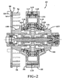
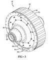
- a building drum 10 has a radially expandable and contractible support means 20.
- the support means 20 has a radially outer surface 24 for building a tread or tread belt reinforcing structure onto the surface 24.
- the surface has a plurality of arcuate or straight segments 22 which are connected by gap spanner segments 21 around the peripheral surface of the tread building support means.
- the arcuate or straight segments 22 and gap spanner segments 21 are slidably attached onto the building drum support means 20.
- Each arcuate segment 22 has a hole or opening 55 for accepting a plurality of pins located on a transfer means 50.
- the pins 54 can be pressed into the openings 55 and provide a means 50 for transferring the arcuate or straight segments and gap spanner segments as an assembly onto and off the support means 20.
- each segment 22 and gap spanner segment 21 may have a flat or straight circumferentially or laterally extending surface or, alternatively, an arcuate surface.
- the segments will be generally referred to as arcuate while it is understood the surface may be straight in either the circumferential direction or the lateral direction.
- the transfer means 50 has an annular transfer ring 51 and a guide ring 52.
- the guide ring 52 is slidably inserted over the pins 54 and the pins 54 are rigidly attached to the transfer ring 51 as shown.
- On the exterior surface of the transfer means 50 are shown three knobs 53.
- a cross sectional view of the building drum 10 is shown along with the transfer means 50.
- the transfer means 50 is shown not engaged to the building drum 10 or to the arcuate or straight segments 22.
- the combination of the arcuate or straight segments 22 and the gap spanner segments 21 form a subassembly commonly referred to as the deck.
- the term "deck” is commonly referred to with a similar meaning as that of the deck of a boat. It is an exterior surface upon which one may stand or build the tread assembly.
- the building surface 24 will be referred to as the deck 24.
- This deck 24, which is an assembly of the arcuate or straight segments 22 and the gap spanning segments 21, is slidably mounted over deck segment guides 116, 117.
- a detent assembly called a deck segment locking pin 115 engages and secures the deck 24 to the drum expansion segment 114.
- the transfer means 50 is pushed into the holes 55 wherein the pins 54 engage the deck segment locking pins 115 thereby releasing them when the pins 54 are fully engaged ( Figs. 3 & 4 ).
- the transfer means 50 may be used to slidably remove the deck assembly 24 ( Fig. 5 ).
- the pins 54 provide radial support for the deck assembly 24 and hold the deck assembly in position for removal.
- a perspective view of the removed deck assembly 24 provides a view of the deck segment guides 116 and 117 and the drum expansion segment 114.
- the arcuate or straight segments 22 have the deck segment locking pin 115 engaged by the pin 54.
- a spring 129 is used in the contracted position when the pin 54 is inserted ( Fig. 6 ). Once the pin 54 is removed, the spring 129 is free to release and allow the locking pin 115 to extend radially inwardly to accomplish the locking of the mechanism.
- the building drum 10 may accept a drive means 30 that provides rotational movement of the entire building drum assembly 10 ( Fig. 7 ).
- the drive means 30 is connected to a motor (not illustrated) which can provide rotational movement of the tire building drum assembly 10.
- the drive means 30 includes a drive spline 100 which is connected to a screw drive shaft 101 and embedded inside a drum quick-mount mounting cone 102.
- the quick-mount mounting cone 102 provides for rapid engagement and disengagement of the drum assembly 10.
- the drum quick-mount mounting cone 102 has a key 104 with a key locating pin 103 and a longitudinally extending keyway 105.
- a drum inboard housing 106 has a corresponding drum outboard housing 107 ( Fig. 7 ).
- An outboard support cone 108 may be disposed on the opposite side of the drive means 20 and the drum assembly 10.
- the outboard support cone 108 may have a live center receptacle 109.
- the live center may permit easy rotation of the drum assembly 10 while the entire assembly is being rotated, as well as both longitudinal and lateral movement.
- a ball screw or acme threaded screw assembly 110 may comprise two components, one having left-hand threads and an opposite side having right-hand threads. These two components may be pinned together to provide simultaneous rotation of the mechanism.
- On the left-hand side may be an inboard ball nut or acme nut 111 connected to one end of the threaded screw 110 and on the opposite or outboard side another ball nut or acme nut 112.
- a ball screw overload protection clutch mechanism 113 may provide capability of disengaging the shaft 110 and permitting the drum assembly 10 to collapse, if the pressure is exceeded beyond the capability of the clutch mechanism.
- This override clutch protection mechanism 113 ensures that, when the mold closes or pressure is applied to the radially outer surface of the deck 24, the deck 24 may collapse as the clutch mechanism 113 disengages, permitting the entire unit or drum 10 to collapse slightly thereby preventing overload from damaging the internal workings of either the mold or the assembly 10.
- Radially inward of the deck 24 or its arcuate or straight segments 22 may be a drum expansion segment 114.
- the drum expansion segments 114 are threadedly engaged by threaded fasteners 125 to an expanding segment base 123.
- the drum expansion segments 114 are also located by pins 122.
- Radially inward of the expanding segment base 114 is an outward outboard segment cone bushing 121 and an inboard segment cone bushing 120 which are threadedly attached using screws or threaded fasteners 126 to the expanding segment base 123.
- Radially inward of the inboard segment bushing 120 Radially inward of the inboard segment bushing 120 is the inboard expansion cone 118.
- the outboard segment cone bushing 121 is an outboard expansion cone 119.
- the bushings 120, 121 are designed to slide along the cone surfaces of the inboard expansion cone 118 and outboard expansion cone 119, respectively.
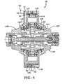
- the building drum 10 may be in an expanded position such that the radially outer deck or building surface 24 is radially expanded.
- the inboard ball nut 111 and outboard ball nut 112 push the expansion cones both inboard and outboard 118, 119, respectively, radially to the center plane of the building drum 10.
- the conical surface permits the expanding segment base 123 and its bushings 120, 121 to slide along the conical surfaces and contract radially inwardly.
- the arcuate or straight segments 22 are shown with a gap G between each segment in the fully radially expanded position ( Fig. 8A ).
- the gap G may be at least 1.25 mm as measured between the adjacent segments.
- the gap spanning segment 21 is constrained in channels 25.
- Each gap spanning segment 21 has lobes 26 that are captured within these channels 25. They may be slid laterally to remove the segments 21, 22, but are constrained such that the arcuate or straight segments 22 can move circumferentially a certain extent until they engage the lobes 26. This permits a diametrical expansion of the assembly 10 by a few millimeters.
- the ends of the segments 22 have a chamfered surface 27 which provides a space for the gap spanning segment 21 to occupy at the correct diameter for tread belt building.
- the arcuate or straight segments close upon each other and the gap spanning segments 21 are moved within the channels 25 such that the lobes 26 contact the interior surface of the arcuate or straight segments 22 ( Fig. 8B ).
- the gap G between the adjacent arcuate or straight segments 22 is closed, permitting each of the segments to contract radially inward.
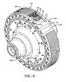
- the tread drum assembly 10 is shown wherein a typical tread belt reinforcing structure 14 is shown assembled to the exterior surface or peripheral surface of the deck 24 ( Fig. 9 ).
- a first belt layer 16 lays adjacent to the surface 24.
- Two belt edge elastomeric strips 17 are located at the lateral edges of the first belt layer 16.
- Interposed between the elastomeric strips 17 is a second belt layer 15 having cords oriented oppositely relative to the first belt layer 16.
- An overlay 18 may be a circumferentially extended cord reinforced structure that "overlays" both the second belt layer 15, the first belt layer 16, and the underlying gum strips 17. Radially outward of the overlay 18 may be an unvulcanized layer 12 of tread rubber.
- the tread rubber 12 may be provided as strips of rubber wound and laid adjacently or may be provided as a single layer.
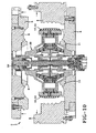
- the entire building drum assembly 10 may be placed inside a curing mold 2 ( Fig. 10 ).
- the tread assembly 14 may be mounted on a building drum 10 that is in a radially expanded position and placed inside the open and expanded curing mold 2.
- the curing mold 2 has tread forming segments 4 on each side, a bottom plate 6, a pair of bead forming rings 11, 9, a top plate 8, and a tread forming segment 5 attached to the top plate.
- the mold maybe closed and the mold segments contract against the tread belt assembly on the tread belt drum assembly 10 ( Fig. 11 A) .
- the tread rubber 12 may then be forced into the tread forming grooves of the segments 4. Once fully contracted, the tread rubber 12 may adhere to the tread forming segments 4. It may be preferred that the tread rubber 12 be warmed or applied to the building drum 10 hot, such that when the mold is closed, the rubber may be relatively softened so that it will easily accept, adapt, and conform to the tread forming segments 4. The tread 12 may be warmed to a temperature of approximately 110°C or between 90 °C and 110°C. Once pressure is applied, assuming the pressure does not exceed the desired limits, the entire tread belt assembly 14 may be adequately adhered to the internal surfaces of the tread forming segments 4.
- the tread belt drum assembly 10 While the mold 2 is still closed, it may be desirable to contract the tread belt drum assembly 10 into a radially contracted position.
- the tread belt 14 will remain in the tread forming segments 4.
- the drum assembly 10 is freed from the tread belt assembly 14 and the top plate 8 of the mold 2 may be removed along with the associated connected components ( Fig. 10 ).
- the tread drum assembly 10 can be removed from the mold 2.
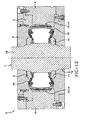
- the tread belt 14 is left in the mold 2 with the segments 4 closed and a tire building drum assembly 7 with a green carcass 72 already mounted to it may be placed into the mold 2.
- the carcass building drum assembly 7 has an axle 70 that is contoured and locked into the mold using locking detents 74 ( Fig. 12 ).
- a gaseous fluid or steam is introduced into the interior through the axle 70 and the internal pressure is applied to the carcass adhering it to the tread belt assembly at the interfacial surfaces.
- the tire is then cured in this self-locking mold 2.
- the clutch mechanism 113 may disengage, allowing the entire assembly 10 to collapse and preventing damage to the mold 2.
- the tread belt assembly 14 may be made on the building drum 10 and the transportability of the building drum 10 may permit the entire assembly to be placed inside a mold 2 whereby the tread belt assembly can be transferred directly to the mold prior to being applied to the carcass 72. Then, the tread building drum assembly 10 may be collapsed and removed from the mold 2 and the entire green carcass 72 on a building drum assembly 7 can be inserted into the mold, locked into position, pressurized, and cured to form a finished tire.
- the tread 12 or tread belt assembly 14 may also be applied to the deck 24 when the deck is set at an outside diameter less than the diameter required to fit precisely in the closed mold position. A small amount of at least 0.5 mm less than the desired finish diameter of the tread belt 14 may be selected.
- the live center receptacle 109 may receive a live center pin 201 for preventing unwanted flexion of the tire building drum assembly 10.
- the live center pin 201 may have two potential movements, longitudinal and transverse. Both longitudinal and transverse movements may be driven by a single actuator 203. Conventional systems typically require an actuator for each direction (e.g., two, three, etc.). Utilization of a single actuator 203 may simplify the assembly and reduce cycle time.
- a system 200 in accordance with the present invention may include a support frame 211, a longitudinal rail 213 slidingly mounted on the support frame, a transverse rail 215 slidingly secured to the longitudinal rail, and a single actuator 203 for moving the longitudinal rail in a longitudinal direction and a transverse direction ( Fig. 13 ).
- the system 200 may further include a link 217 pivotally secured about vertical axes to the actuator 203 and the transverse rail 215.
- the actuator 203 may include a cylinder associated with an actuation rod 225.
- the actuator 203 may be secured to the support frame 211 such that, when the cylinder acts on the rod 225, the longitudinal rail 213 moves in the longitudinal direction.
- the link 217 may be pivotally secured to an end of the actuation rod 225.
- the system 200 may have a first movement and a second movement.
- the first movement may begin with the system 200 in a first condition shown in Fig. 13 and terminate with the system in a second condition shown in Fig. 14 .
- the live center pin 201 has moved in the longitudinal direction to the second position determined by a longitudinal stop 229.
- a spring 219 is positioned about the actuation rod 225 such that the stiffness of the spring is greater than the force of friction encountered by the actuator 203 in moving the longitudinal rail 213 to the second position ( Fig. 14 ).
- the actuation rod 225 may still continue to exert a force on the longitudinal rail 213.
- the actuation rod 225 may begin to compress the spring 219 thereby initiating the second movement from the second condition ( Fig 14 ) to a third condition ( Fig. 15 ).
- the actuation rod 225 acts on the link 217.
- the orientation (e.g., 45 degrees to both longitudinal and transverse directions) and pivotal mounting cause the link 217 to transfer the longitudinal force of the actuation rod 225 to a transverse force acting on the transverse rail 215 and the live center pin 201.
- the live center pin 201 thus reaches the third condition ( Fig. 15 ), having moved sequentially longitudinally, and then transversely.
Landscapes
- Engineering & Computer Science (AREA)
- Mechanical Engineering (AREA)
- Tyre Moulding (AREA)
Claims (12)
- Verfahren zum Tragen einer Reifenbauanordnung, wobei das Verfahren die Schritte umfasst des:Tragens eines Endteils einer radial einklappbaren Aufbautrommel (10) zum Zusammenbau eines Reifenrohlings;Bewegens des Endteils in einer ersten Richtung durch einen in der ersten Richtung wirkenden Stellantrieb; undBewegens des Endteils in einer zweiten Richtung durch den in der ersten Richtung wirkenden Stellantrieb.
- Verfahren, wie in Anspruch 1 dargelegt, wobei die erste Richtung sich in einer horizontalen Ebene neunzig Grad in Bezug zu der zweiten Richtung erstreckt.
- Verfahren, wie in Anspruch 1 oder 2 dargelegt, weiter den Schritt des Bewegens einer Längsschiene (213) in der ersten Richtung und/oder Bewegens einer Querschiene (215) in der zweiten Richtung beinhaltend.
- Verfahren, wie in mindestens einem der vorgenannten Ansprüche dargelegt, weiter den Schritt des schwenkenden Sicherns eines Verbindungsglieds an dem Stellantrieb und dem Endteil beinhaltend.
- Verfahren, wie in mindestens einem der vorgenannten Ansprüche dargelegt, weiter den Schritt des Positionierens einer Feder (219) um eine Betätigungsstange des Stellantriebs beinhaltend.
- Verfahren, wie in mindestens einem der vorgenannten Ansprüche dargelegt, weiter den Schritt des Zusammendrückens einer Feder durch den Stellantrieb beinhaltend.
- Verfahren, wie in mindestens einem der vorgenannten Ansprüche dargelegt, weiter den Schritt des Verschiebens einer Schiene in der zweiten Richtung beinhaltend.
- Anordnung zum Bewegen eines Endteils einer Reifenbauanordnung, umfassend ein Traggestell (211) zum Tragen des Endteils; eine Längsschiene (213), die verschiebbar an dem Traggestell (211) montiert ist; eine Querschiene (215), die verschiebbar an der Längsschiene (213) montiert ist; und einen Stellantrieb zum Bewegen der Längsschiene (213) in einer ersten Richtung in Bezug auf das Traggestell (211), wobei der Stellantrieb auch die Querschiene (215) in einer zweiten Richtung in Bezug auf das Traggestell (211) und die Längsschiene (213) bewegt.
- Anordnung, wie in Anspruch 8 dargelegt, weiter ein schwenkbar an sowohl der Längsschiene (213) als auch der Querschiene (215) gesichertes Verbindungsglied beinhaltend.
- Anordnung, wie in Anspruch 8 oder 9 dargelegt, wobei der Stellantrieb einen Zylinder, eine Betätigungsstange (225) und eine Feder (219), die gegen Bewegung in der ersten Richtung wirkt, beinhaltet.
- Anordnung, wie in mindestens einem der vorgenannten Ansprüche 8 bis 10 dargelegt, weiter ein Verbindungsglied zum Überführen einer Längskraft des Stellantriebs in eine Querkraft, die in neunzig Grad in Bezug zu der Längskraft wirkt, beinhaltend.
- Anordnung, wie in mindestens einem der vorgenannten Ansprüche 8 bis 10 dargelegt, weiter einen Anschlag zur Begrenzung der Bewegung der Längsschiene (213) in der ersten Richtung beinhaltend.
Applications Claiming Priority (1)
| Application Number | Priority Date | Filing Date | Title |
|---|---|---|---|
| US13/269,014 US8991804B2 (en) | 2011-10-07 | 2011-10-07 | Method and apparatus for adjusting a tire building machine |
Publications (2)
| Publication Number | Publication Date |
|---|---|
| EP2578385A1 EP2578385A1 (de) | 2013-04-10 |
| EP2578385B1 true EP2578385B1 (de) | 2014-07-16 |
Family
ID=47172284
Family Applications (1)
| Application Number | Title | Priority Date | Filing Date |
|---|---|---|---|
| EP12187495.2A Not-in-force EP2578385B1 (de) | 2011-10-07 | 2012-10-05 | Verfahren und Vorrichtung zum Tragen und Bewegen einer Reifenaufbautrommel |
Country Status (3)
| Country | Link |
|---|---|
| US (2) | US8991804B2 (de) |
| EP (1) | EP2578385B1 (de) |
| CN (1) | CN103029312B (de) |
Families Citing this family (4)
| Publication number | Priority date | Publication date | Assignee | Title |
|---|---|---|---|---|
| US8991804B2 (en) * | 2011-10-07 | 2015-03-31 | The Goodyear Tire & Rubber Company | Method and apparatus for adjusting a tire building machine |
| CN105751545B (zh) * | 2016-03-30 | 2017-12-08 | 萨驰华辰机械(苏州)有限公司 | 一种钢圈分离系统及其对应的钢圈分离方法 |
| CN110667156B (zh) * | 2019-10-10 | 2024-07-23 | 软控股份有限公司 | 定位设备及定位方法 |
| CN118061573B (zh) * | 2024-04-25 | 2024-06-18 | 山东优盛轮胎有限公司 | 一种橡胶轮胎加工用环保硫化设备 |
Family Cites Families (28)
| Publication number | Priority date | Publication date | Assignee | Title |
|---|---|---|---|---|
| GB1039608A (en) | 1962-05-11 | 1966-08-17 | Du Pont | Improvements in or relating to pneumatic tyre manufacture |
| FR1544189A (fr) | 1967-09-18 | 1968-10-31 | Uniroyal Englebert France | Appareillage de confection automatique de carcasses radiales d'enveloppes de pneumatiques |
| LU60972A1 (de) | 1969-05-31 | 1970-08-04 | ||
| US3784437A (en) | 1969-11-28 | 1974-01-08 | Goodyear Tire & Rubber | Tire building apparatus |
| US3782871A (en) | 1971-05-17 | 1974-01-01 | Nrm Corp | Care for tire molding machine |
| US3868203A (en) | 1971-05-17 | 1975-02-25 | Nrm Corp | Tire molding machine |
| US3865670A (en) | 1972-12-29 | 1975-02-11 | Uniroyal Inc | Breaker-tread assembly transfer ring size changing mechanism |
| US3865669A (en) | 1973-01-08 | 1975-02-11 | Uniroyal Inc | Expansible and contractible transfer ring |
| US3888720A (en) | 1973-02-05 | 1975-06-10 | Uniroyal Inc | Tire building machine having a variable diameter tire building drum |
| AT339757B (de) | 1975-10-03 | 1977-11-10 | Polyair Maschinenbau Gmbh | Vorrichtung zum giessen oder spritzen von fahrzeugreifen |
| US4087305A (en) | 1976-06-01 | 1978-05-02 | The Goodyear Tire & Rubber Company | Building arbor for tires and like articles having inextensible bead rings |
| US4210482A (en) * | 1978-10-25 | 1980-07-01 | Eaton Corporation | Variable width tire building drum |
| US4362456A (en) | 1978-11-06 | 1982-12-07 | Barry Leonard D | Rotary loader and storage system |
| US4268330A (en) | 1978-12-29 | 1981-05-19 | Bridgestone Tire Company Limited | Green tire building process and apparatus |
| DE2900565A1 (de) | 1979-01-09 | 1980-07-17 | Bayer Ag | Verfahren und vorrichtung zur reifenentformung bei segmentierten kernen |
| US4614562A (en) * | 1984-08-13 | 1986-09-30 | The B. F. Goodrich Company | Tires building machine with rigid radially expansible drum |
| US5201975A (en) | 1987-11-13 | 1993-04-13 | Bridgestone/Firestone Inc. | Tire manufacture |
| JPH089204B2 (ja) | 1990-07-25 | 1996-01-31 | 住友ゴム工業株式会社 | 生タイヤの成形方法及びベルト成形ドラム |
| JPH0757537B2 (ja) | 1991-03-20 | 1995-06-21 | 株式会社森鐵工所 | タイヤ成型ドラム装置における可動部を駆動するための装置およびそれを使用したタイヤ成型ドラム装置 |
| IT1250031B (it) | 1991-10-31 | 1995-03-30 | Firestone Int Dev Spa | Procedimento per la realizzazione di un assieme esterno di battistrada |
| US6139668A (en) | 1996-09-18 | 2000-10-31 | The Goodyear Tire & Rubber Company | Method and apparatus for simultaneously assembling a plurality of tires |
| DE19742035C1 (de) | 1997-09-24 | 1999-04-08 | Continental Ag | Verfahren und Trommel als Vorrichtung zum Aufbau eines Reifenrohlinges |
| US6863760B2 (en) | 2001-09-21 | 2005-03-08 | The Goodyear Tire & Rubber Company | Stabilizer for cantilevered tire building drum |
| US6966958B2 (en) * | 2001-09-21 | 2005-11-22 | The Goodyear Tire & Rubber Company | Precision alignment of tire building drum to automated tire building system working axis |
| US20040231779A1 (en) | 2003-05-20 | 2004-11-25 | Jean-Claude Girard | Method and apparatus for tread belt assembly |
| US20070125497A1 (en) * | 2005-12-02 | 2007-06-07 | Lundell Dennis A | Heated tire building core assembly and method |
| BRPI0722279B1 (pt) * | 2007-11-30 | 2018-09-25 | Pirelli | método de construção de pelo menos uma lona de carcaça, processo para fabricação de pneus, e, aparelho para fabricação de pneus |
| US8991804B2 (en) * | 2011-10-07 | 2015-03-31 | The Goodyear Tire & Rubber Company | Method and apparatus for adjusting a tire building machine |
-
2011
- 2011-10-07 US US13/269,014 patent/US8991804B2/en not_active Expired - Fee Related
-
2012
- 2012-09-28 CN CN201210366675.9A patent/CN103029312B/zh not_active Expired - Fee Related
- 2012-10-05 EP EP12187495.2A patent/EP2578385B1/de not_active Not-in-force
-
2015
- 2015-01-30 US US14/609,997 patent/US9662848B2/en not_active Expired - Fee Related
Also Published As
| Publication number | Publication date |
|---|---|
| CN103029312B (zh) | 2015-06-17 |
| EP2578385A1 (de) | 2013-04-10 |
| US20130087962A1 (en) | 2013-04-11 |
| CN103029312A (zh) | 2013-04-10 |
| US9662848B2 (en) | 2017-05-30 |
| US20150144269A1 (en) | 2015-05-28 |
| US8991804B2 (en) | 2015-03-31 |
Similar Documents
| Publication | Publication Date | Title |
|---|---|---|
| EP3037249B1 (de) | Manschettenlose reifenbautrommel | |
| EP2698243B1 (de) | Manschettenlose Reifenbautrommel | |
| US7628599B2 (en) | Self-locking tire mold apparatus | |
| EP2868463B1 (de) | Reifenbautrommel | |
| EP2698244B1 (de) | Manschettenlose Reifenbautrommel mit auswechselbaren Breitenelementen | |
| KR101929054B1 (ko) | 연속 데크 비드 로크 드럼 | |
| EP1810818B1 (de) | Vorrichtung zur Herstellung und Übertragung von Laufstreifen/Gürtelpaketen für Fahrzeugluftreifen | |
| US9662848B2 (en) | Method and apparatus for adjusting a tire building machine | |
| JP6933928B2 (ja) | タイヤ組立てドラム用の中心機構 | |
| EP1793981B1 (de) | Verfahren und anlage zur herstellung von reifen | |
| EP1793980B1 (de) | Verfahren und vorrichtung zur herstellung von reifen | |
| US20100032079A1 (en) | Process and apparatus for manufacturing tyres | |
| JP6736961B2 (ja) | 溝形成装置 | |
| JP2006224521A (ja) | タイヤ成形機 |
Legal Events
| Date | Code | Title | Description |
|---|---|---|---|
| PUAI | Public reference made under article 153(3) epc to a published international application that has entered the european phase |
Free format text: ORIGINAL CODE: 0009012 |
|
| AK | Designated contracting states |
Kind code of ref document: A1 Designated state(s): AL AT BE BG CH CY CZ DE DK EE ES FI FR GB GR HR HU IE IS IT LI LT LU LV MC MK MT NL NO PL PT RO RS SE SI SK SM TR |
|
| AX | Request for extension of the european patent |
Extension state: BA ME |
|
| GRAP | Despatch of communication of intention to grant a patent |
Free format text: ORIGINAL CODE: EPIDOSNIGR1 |
|
| 17P | Request for examination filed |
Effective date: 20131010 |
|
| RBV | Designated contracting states (corrected) |
Designated state(s): AL AT BE BG CH CY CZ DE DK EE ES FI FR GB GR HR HU IE IS IT LI LT LU LV MC MK MT NL NO PL PT RO RS SE SI SK SM TR |
|
| INTG | Intention to grant announced |
Effective date: 20131120 |
|
| GRAS | Grant fee paid |
Free format text: ORIGINAL CODE: EPIDOSNIGR3 |
|
| GRAA | (expected) grant |
Free format text: ORIGINAL CODE: 0009210 |
|
| AK | Designated contracting states |
Kind code of ref document: B1 Designated state(s): AL AT BE BG CH CY CZ DE DK EE ES FI FR GB GR HR HU IE IS IT LI LT LU LV MC MK MT NL NO PL PT RO RS SE SI SK SM TR |
|
| REG | Reference to a national code |
Ref country code: GB Ref legal event code: FG4D |
|
| REG | Reference to a national code |
Ref country code: CH Ref legal event code: EP |
|
| REG | Reference to a national code |
Ref country code: IE Ref legal event code: FG4D |
|
| REG | Reference to a national code |
Ref country code: AT Ref legal event code: REF Ref document number: 677338 Country of ref document: AT Kind code of ref document: T Effective date: 20140815 |
|
| REG | Reference to a national code |
Ref country code: DE Ref legal event code: R096 Ref document number: 602012002436 Country of ref document: DE Effective date: 20140828 |
|
| REG | Reference to a national code |
Ref country code: NL Ref legal event code: T3 |
|
| REG | Reference to a national code |
Ref country code: AT Ref legal event code: MK05 Ref document number: 677338 Country of ref document: AT Kind code of ref document: T Effective date: 20140716 |
|
| REG | Reference to a national code |
Ref country code: LT Ref legal event code: MG4D |
|
| PG25 | Lapsed in a contracting state [announced via postgrant information from national office to epo] |
Ref country code: ES Free format text: LAPSE BECAUSE OF FAILURE TO SUBMIT A TRANSLATION OF THE DESCRIPTION OR TO PAY THE FEE WITHIN THE PRESCRIBED TIME-LIMIT Effective date: 20140716 Ref country code: GR Free format text: LAPSE BECAUSE OF FAILURE TO SUBMIT A TRANSLATION OF THE DESCRIPTION OR TO PAY THE FEE WITHIN THE PRESCRIBED TIME-LIMIT Effective date: 20141017 Ref country code: BG Free format text: LAPSE BECAUSE OF FAILURE TO SUBMIT A TRANSLATION OF THE DESCRIPTION OR TO PAY THE FEE WITHIN THE PRESCRIBED TIME-LIMIT Effective date: 20141016 Ref country code: PT Free format text: LAPSE BECAUSE OF FAILURE TO SUBMIT A TRANSLATION OF THE DESCRIPTION OR TO PAY THE FEE WITHIN THE PRESCRIBED TIME-LIMIT Effective date: 20141117 Ref country code: NO Free format text: LAPSE BECAUSE OF FAILURE TO SUBMIT A TRANSLATION OF THE DESCRIPTION OR TO PAY THE FEE WITHIN THE PRESCRIBED TIME-LIMIT Effective date: 20141016 Ref country code: FI Free format text: LAPSE BECAUSE OF FAILURE TO SUBMIT A TRANSLATION OF THE DESCRIPTION OR TO PAY THE FEE WITHIN THE PRESCRIBED TIME-LIMIT Effective date: 20140716 Ref country code: SE Free format text: LAPSE BECAUSE OF FAILURE TO SUBMIT A TRANSLATION OF THE DESCRIPTION OR TO PAY THE FEE WITHIN THE PRESCRIBED TIME-LIMIT Effective date: 20140716 Ref country code: LT Free format text: LAPSE BECAUSE OF FAILURE TO SUBMIT A TRANSLATION OF THE DESCRIPTION OR TO PAY THE FEE WITHIN THE PRESCRIBED TIME-LIMIT Effective date: 20140716 |
|
| PG25 | Lapsed in a contracting state [announced via postgrant information from national office to epo] |
Ref country code: RS Free format text: LAPSE BECAUSE OF FAILURE TO SUBMIT A TRANSLATION OF THE DESCRIPTION OR TO PAY THE FEE WITHIN THE PRESCRIBED TIME-LIMIT Effective date: 20140716 Ref country code: AT Free format text: LAPSE BECAUSE OF FAILURE TO SUBMIT A TRANSLATION OF THE DESCRIPTION OR TO PAY THE FEE WITHIN THE PRESCRIBED TIME-LIMIT Effective date: 20140716 Ref country code: PL Free format text: LAPSE BECAUSE OF FAILURE TO SUBMIT A TRANSLATION OF THE DESCRIPTION OR TO PAY THE FEE WITHIN THE PRESCRIBED TIME-LIMIT Effective date: 20140716 Ref country code: IS Free format text: LAPSE BECAUSE OF FAILURE TO SUBMIT A TRANSLATION OF THE DESCRIPTION OR TO PAY THE FEE WITHIN THE PRESCRIBED TIME-LIMIT Effective date: 20141116 Ref country code: CY Free format text: LAPSE BECAUSE OF FAILURE TO SUBMIT A TRANSLATION OF THE DESCRIPTION OR TO PAY THE FEE WITHIN THE PRESCRIBED TIME-LIMIT Effective date: 20140716 Ref country code: LV Free format text: LAPSE BECAUSE OF FAILURE TO SUBMIT A TRANSLATION OF THE DESCRIPTION OR TO PAY THE FEE WITHIN THE PRESCRIBED TIME-LIMIT Effective date: 20140716 |
|
| REG | Reference to a national code |
Ref country code: DE Ref legal event code: R097 Ref document number: 602012002436 Country of ref document: DE |
|
| PG25 | Lapsed in a contracting state [announced via postgrant information from national office to epo] |
Ref country code: SK Free format text: LAPSE BECAUSE OF FAILURE TO SUBMIT A TRANSLATION OF THE DESCRIPTION OR TO PAY THE FEE WITHIN THE PRESCRIBED TIME-LIMIT Effective date: 20140716 Ref country code: DK Free format text: LAPSE BECAUSE OF FAILURE TO SUBMIT A TRANSLATION OF THE DESCRIPTION OR TO PAY THE FEE WITHIN THE PRESCRIBED TIME-LIMIT Effective date: 20140716 Ref country code: RO Free format text: LAPSE BECAUSE OF FAILURE TO SUBMIT A TRANSLATION OF THE DESCRIPTION OR TO PAY THE FEE WITHIN THE PRESCRIBED TIME-LIMIT Effective date: 20140716 Ref country code: CZ Free format text: LAPSE BECAUSE OF FAILURE TO SUBMIT A TRANSLATION OF THE DESCRIPTION OR TO PAY THE FEE WITHIN THE PRESCRIBED TIME-LIMIT Effective date: 20140716 Ref country code: EE Free format text: LAPSE BECAUSE OF FAILURE TO SUBMIT A TRANSLATION OF THE DESCRIPTION OR TO PAY THE FEE WITHIN THE PRESCRIBED TIME-LIMIT Effective date: 20140716 |
|
| PLBE | No opposition filed within time limit |
Free format text: ORIGINAL CODE: 0009261 |
|
| STAA | Information on the status of an ep patent application or granted ep patent |
Free format text: STATUS: NO OPPOSITION FILED WITHIN TIME LIMIT |
|
| PG25 | Lapsed in a contracting state [announced via postgrant information from national office to epo] |
Ref country code: LU Free format text: LAPSE BECAUSE OF FAILURE TO SUBMIT A TRANSLATION OF THE DESCRIPTION OR TO PAY THE FEE WITHIN THE PRESCRIBED TIME-LIMIT Effective date: 20141005 Ref country code: MC Free format text: LAPSE BECAUSE OF FAILURE TO SUBMIT A TRANSLATION OF THE DESCRIPTION OR TO PAY THE FEE WITHIN THE PRESCRIBED TIME-LIMIT Effective date: 20140716 |
|
| 26N | No opposition filed |
Effective date: 20150417 |
|
| PG25 | Lapsed in a contracting state [announced via postgrant information from national office to epo] |
Ref country code: BE Free format text: LAPSE BECAUSE OF NON-PAYMENT OF DUE FEES Effective date: 20141031 |
|
| REG | Reference to a national code |
Ref country code: IE Ref legal event code: MM4A |
|
| REG | Reference to a national code |
Ref country code: FR Ref legal event code: PLFP Year of fee payment: 4 |
|
| PG25 | Lapsed in a contracting state [announced via postgrant information from national office to epo] |
Ref country code: IE Free format text: LAPSE BECAUSE OF NON-PAYMENT OF DUE FEES Effective date: 20141005 |
|
| PG25 | Lapsed in a contracting state [announced via postgrant information from national office to epo] |
Ref country code: SI Free format text: LAPSE BECAUSE OF FAILURE TO SUBMIT A TRANSLATION OF THE DESCRIPTION OR TO PAY THE FEE WITHIN THE PRESCRIBED TIME-LIMIT Effective date: 20140716 |
|
| PGFP | Annual fee paid to national office [announced via postgrant information from national office to epo] |
Ref country code: FR Payment date: 20150924 Year of fee payment: 4 |
|
| PGFP | Annual fee paid to national office [announced via postgrant information from national office to epo] |
Ref country code: IT Payment date: 20151031 Year of fee payment: 4 Ref country code: DE Payment date: 20151030 Year of fee payment: 4 |
|
| PGFP | Annual fee paid to national office [announced via postgrant information from national office to epo] |
Ref country code: NL Payment date: 20151007 Year of fee payment: 4 |
|
| REG | Reference to a national code |
Ref country code: CH Ref legal event code: PL |
|
| PG25 | Lapsed in a contracting state [announced via postgrant information from national office to epo] |
Ref country code: HU Free format text: LAPSE BECAUSE OF FAILURE TO SUBMIT A TRANSLATION OF THE DESCRIPTION OR TO PAY THE FEE WITHIN THE PRESCRIBED TIME-LIMIT; INVALID AB INITIO Effective date: 20121005 Ref country code: BE Free format text: LAPSE BECAUSE OF FAILURE TO SUBMIT A TRANSLATION OF THE DESCRIPTION OR TO PAY THE FEE WITHIN THE PRESCRIBED TIME-LIMIT Effective date: 20140716 Ref country code: MT Free format text: LAPSE BECAUSE OF FAILURE TO SUBMIT A TRANSLATION OF THE DESCRIPTION OR TO PAY THE FEE WITHIN THE PRESCRIBED TIME-LIMIT Effective date: 20140716 Ref country code: HR Free format text: LAPSE BECAUSE OF FAILURE TO SUBMIT A TRANSLATION OF THE DESCRIPTION OR TO PAY THE FEE WITHIN THE PRESCRIBED TIME-LIMIT Effective date: 20140716 Ref country code: LI Free format text: LAPSE BECAUSE OF NON-PAYMENT OF DUE FEES Effective date: 20151031 Ref country code: CH Free format text: LAPSE BECAUSE OF NON-PAYMENT OF DUE FEES Effective date: 20151031 Ref country code: TR Free format text: LAPSE BECAUSE OF FAILURE TO SUBMIT A TRANSLATION OF THE DESCRIPTION OR TO PAY THE FEE WITHIN THE PRESCRIBED TIME-LIMIT Effective date: 20140716 |
|
| REG | Reference to a national code |
Ref country code: DE Ref legal event code: R119 Ref document number: 602012002436 Country of ref document: DE |
|
| PG25 | Lapsed in a contracting state [announced via postgrant information from national office to epo] |
Ref country code: SM Free format text: LAPSE BECAUSE OF FAILURE TO SUBMIT A TRANSLATION OF THE DESCRIPTION OR TO PAY THE FEE WITHIN THE PRESCRIBED TIME-LIMIT Effective date: 20140716 |
|
| REG | Reference to a national code |
Ref country code: NL Ref legal event code: MM Effective date: 20161101 |
|
| GBPC | Gb: european patent ceased through non-payment of renewal fee |
Effective date: 20161005 |
|
| REG | Reference to a national code |
Ref country code: FR Ref legal event code: ST Effective date: 20170630 |
|
| PG25 | Lapsed in a contracting state [announced via postgrant information from national office to epo] |
Ref country code: DE Free format text: LAPSE BECAUSE OF NON-PAYMENT OF DUE FEES Effective date: 20170503 Ref country code: FR Free format text: LAPSE BECAUSE OF NON-PAYMENT OF DUE FEES Effective date: 20161102 Ref country code: GB Free format text: LAPSE BECAUSE OF NON-PAYMENT OF DUE FEES Effective date: 20161005 |
|
| PG25 | Lapsed in a contracting state [announced via postgrant information from national office to epo] |
Ref country code: NL Free format text: LAPSE BECAUSE OF NON-PAYMENT OF DUE FEES Effective date: 20161101 |
|
| PG25 | Lapsed in a contracting state [announced via postgrant information from national office to epo] |
Ref country code: IT Free format text: LAPSE BECAUSE OF NON-PAYMENT OF DUE FEES Effective date: 20161005 |
|
| PG25 | Lapsed in a contracting state [announced via postgrant information from national office to epo] |
Ref country code: MK Free format text: LAPSE BECAUSE OF FAILURE TO SUBMIT A TRANSLATION OF THE DESCRIPTION OR TO PAY THE FEE WITHIN THE PRESCRIBED TIME-LIMIT Effective date: 20140716 |
|
| PG25 | Lapsed in a contracting state [announced via postgrant information from national office to epo] |
Ref country code: AL Free format text: LAPSE BECAUSE OF FAILURE TO SUBMIT A TRANSLATION OF THE DESCRIPTION OR TO PAY THE FEE WITHIN THE PRESCRIBED TIME-LIMIT Effective date: 20140716 |