EP2578785A2 - Führungsschiene und Führungsschienenanordnung für eine Falt-/Schiebetür - Google Patents
Führungsschiene und Führungsschienenanordnung für eine Falt-/Schiebetür Download PDFInfo
- Publication number
- EP2578785A2 EP2578785A2 EP12187217.0A EP12187217A EP2578785A2 EP 2578785 A2 EP2578785 A2 EP 2578785A2 EP 12187217 A EP12187217 A EP 12187217A EP 2578785 A2 EP2578785 A2 EP 2578785A2
- Authority
- EP
- European Patent Office
- Prior art keywords
- guide rail
- alignment
- guide
- folding
- channels
- Prior art date
- Legal status (The legal status is an assumption and is not a legal conclusion. Google has not performed a legal analysis and makes no representation as to the accuracy of the status listed.)
- Withdrawn
Links
Images
Classifications
-
- E—FIXED CONSTRUCTIONS
- E05—LOCKS; KEYS; WINDOW OR DOOR FITTINGS; SAFES
- E05D—HINGES OR SUSPENSION DEVICES FOR DOORS, WINDOWS OR WINGS
- E05D15/00—Suspension arrangements for wings
- E05D15/06—Suspension arrangements for wings for wings sliding horizontally more or less in their own plane
- E05D15/0621—Details, e.g. suspension or supporting guides
- E05D15/0626—Details, e.g. suspension or supporting guides for wings suspended at the top
- E05D15/0652—Tracks
-
- E—FIXED CONSTRUCTIONS
- E05—LOCKS; KEYS; WINDOW OR DOOR FITTINGS; SAFES
- E05D—HINGES OR SUSPENSION DEVICES FOR DOORS, WINDOWS OR WINGS
- E05D15/00—Suspension arrangements for wings
- E05D15/06—Suspension arrangements for wings for wings sliding horizontally more or less in their own plane
- E05D15/0621—Details, e.g. suspension or supporting guides
- E05D15/066—Details, e.g. suspension or supporting guides for wings supported at the bottom
- E05D15/0686—Tracks
-
- E—FIXED CONSTRUCTIONS
- E05—LOCKS; KEYS; WINDOW OR DOOR FITTINGS; SAFES
- E05Y—INDEXING SCHEME ASSOCIATED WITH SUBCLASSES E05D AND E05F, RELATING TO CONSTRUCTION ELEMENTS, ELECTRIC CONTROL, POWER SUPPLY, POWER SIGNAL OR TRANSMISSION, USER INTERFACES, MOUNTING OR COUPLING, DETAILS, ACCESSORIES, AUXILIARY OPERATIONS NOT OTHERWISE PROVIDED FOR, APPLICATION THEREOF
- E05Y2600/00—Mounting or coupling arrangements for elements provided for in this subclass
- E05Y2600/60—Mounting or coupling members; Accessories therefor
- E05Y2600/628—Profiles; Strips
-
- E—FIXED CONSTRUCTIONS
- E05—LOCKS; KEYS; WINDOW OR DOOR FITTINGS; SAFES
- E05Y—INDEXING SCHEME ASSOCIATED WITH SUBCLASSES E05D AND E05F, RELATING TO CONSTRUCTION ELEMENTS, ELECTRIC CONTROL, POWER SUPPLY, POWER SIGNAL OR TRANSMISSION, USER INTERFACES, MOUNTING OR COUPLING, DETAILS, ACCESSORIES, AUXILIARY OPERATIONS NOT OTHERWISE PROVIDED FOR, APPLICATION THEREOF
- E05Y2800/00—Details, accessories and auxiliary operations not otherwise provided for
- E05Y2800/20—Combinations of elements
- E05Y2800/205—Combinations of elements forming a unit
-
- E—FIXED CONSTRUCTIONS
- E05—LOCKS; KEYS; WINDOW OR DOOR FITTINGS; SAFES
- E05Y—INDEXING SCHEME ASSOCIATED WITH SUBCLASSES E05D AND E05F, RELATING TO CONSTRUCTION ELEMENTS, ELECTRIC CONTROL, POWER SUPPLY, POWER SIGNAL OR TRANSMISSION, USER INTERFACES, MOUNTING OR COUPLING, DETAILS, ACCESSORIES, AUXILIARY OPERATIONS NOT OTHERWISE PROVIDED FOR, APPLICATION THEREOF
- E05Y2800/00—Details, accessories and auxiliary operations not otherwise provided for
- E05Y2800/20—Combinations of elements
- E05Y2800/21—Combinations of elements of identical elements, e.g. of identical compression springs
-
- E—FIXED CONSTRUCTIONS
- E05—LOCKS; KEYS; WINDOW OR DOOR FITTINGS; SAFES
- E05Y—INDEXING SCHEME ASSOCIATED WITH SUBCLASSES E05D AND E05F, RELATING TO CONSTRUCTION ELEMENTS, ELECTRIC CONTROL, POWER SUPPLY, POWER SIGNAL OR TRANSMISSION, USER INTERFACES, MOUNTING OR COUPLING, DETAILS, ACCESSORIES, AUXILIARY OPERATIONS NOT OTHERWISE PROVIDED FOR, APPLICATION THEREOF
- E05Y2900/00—Application of doors, windows, wings or fittings thereof
- E05Y2900/10—Application of doors, windows, wings or fittings thereof for buildings or parts thereof
- E05Y2900/13—Type of wing
- E05Y2900/132—Doors
Definitions
- This invention relates to a guide rail and to a guide rail assembly for a folding/sliding door.
- Folding/sliding doors are a particular type of door for closing an opening in the wall of a building.
- a folding/sliding door will often be used as an alternative to a patio door for example, and is distinguished in that the door panels fold together in concertina fashion when the door is opened, rather than one door panel sliding over (and parallel to) a fixed door panel as occurs with a typical patio door.
- the door panels will be of a height to span the distance between the top and bottom of the opening, so that the folding/sliding door comprises the required number of panels arranged side by side to span the width of the opening.
- Each of the door panels typically comprises a substantially rigid frame surrounding a glazing panel.
- Respective sets of hinges connect adjacent panels together.
- Alternate hinges are mounted upon a respective carriage, the carriage being located in one of two guide rails, the guide rails being mounted at the top and bottom of the opening.
- the hinges which are mounted upon carriages are “captive” in that they are located by the guide rails and are restricted to movement along the guide rails.
- the intermediate hinges i.e. those hinges which are not mounted upon a carriage, are free to move out of alignment with the guide rails when the door is opened. This alternating arrangement of “captive” and “free” hinges allows the door panels to open in a concertina fashion.
- Folding/sliding doors have the particular advantage that they maximise the size of the opening which is available for ventilation or access.
- a patio door for example, will typically comprise one fixed panel and one sliding panel. Since only the sliding panel is movable a fully-opened patio door can provide slightly less than half of the opening for ventilation or access.
- a folding/sliding door on the other hand can usually provide almost all of the opening for ventilation or access.
- folding/sliding doors are particularly beneficial for buildings containing private swimming pools for example, and also for restaurants having indoor and outdoor areas which can be separated when desired by closing the folding/sliding door, or combined into substantially a single area when the door is opened.
- the guide rails are therefore typically made as one-piece extrusions or channel sections, so as to avoid discontinuities or junctions which might hinder the passage of a carriage.
- folding/sliding doors are, however, several metres wide (folding/sliding doors having a width of 7 metres are not unusual). It is very difficult to ensure that a guide rail of such a length will reach the site of use without damage or distortion which will at least hinder the passage of the carriage and therefore increase the force required to open and/or close the door, and at most make the guide rail unusable.
- the inventors have appreciated the fact that the need to replace a damaged guide rail will reduce (or in some cases avoid) the profit which an installer might otherwise make when installing a folding/sliding door.
- the inventors wish to reduce the high failure rate in the existing guide rails, caused by the frequent incidences of damaged or distorted guide rails.
- the inventors therefore seek to reduce the likelihood of the installers being required to replace a guide rail and therefore increasing the likelihood that the installer will achieve the intended profit.
- a guide rail for a folding/sliding door comprising a channel section adapted to accommodate the carriage(s) of the folding/sliding door, the guide rail including at least two alignment channels, the alignment channels being adapted to accommodate an alignment member.
- the invention therefore provides a guide rail which is designed to accommodate at least two alignment members.
- the alignment members are used to align adjacent lengths of the guide rail, whereby the guide rail for a folding/sliding door can be made in relatively short lengths, and in particular lengths which are more easily transported to and around a site of use, and are less vulnerable to damage or distortion.
- the provision of two alignment members helps to ensure that when adjacent lengths of guide rail are interconnected they are aligned sufficiently accurately so that the carriage can pass along the complete guide rail, and in particular can pass the junction between one length of guide rail to a neighbouring length of guide rail, without significant hindrance.
- the guide rail includes a pair of guide ribs, the guide ribs being positioned to accommodate the wheels or rollers of the carriage.
- the pair of guide ribs are located between the alignment channels.
- guide rails having guide ribs it is the guide ribs of adjacent lengths of guide rail which must be aligned, and more accurate alignment of the guide ribs is achieved by locating the alignment channels outside of the guide ribs (so that the alignment channels "surround" the guide ribs).
- the guide rail includes four guide ribs, arranged in two pairs.
- a first pair of guide ribs is provided for use when the guide rail is located at the bottom of the opening (so that the carriage rests upon the first pair of guide ribs).
- a second pair of guide ribs is provided for use when the guide rail is located at the top of the opening (so that the carriage is suspended from the second pair of guide rails).
- a guide rail of the same form (such as a common extrusion) can be used at the top and bottom of the opening.
- a guide rail assembly for a folding/sliding door, the guide rail assembly including at least two guide rails of similar cross-sectional form, each guide rail comprising a channel section adapted to accommodate the carriage(s) of the folding/sliding door, each guide rail including at least two alignment channels, the assembly including at least two alignment members adapted to fit into the alignment channels of the respective guide rails whereby to align the guide rails.
- the alignment channels are of dovetail form.
- the alignment members are a tight fit into the alignment channels so that it is necessary to drive each alignment member into an alignment channel.
- the alignment member includes a positioning rib, the positioning rib preferably being located substantially at its longitudinal centre, the positioning rib serving to limit the distance by which the alignment member is driven into the alignment channel. In this way, it can be ensured that an approximately equal length of the alignment member is located in the alignment channels of the adjacent guide rails.
- the guide rail is an aluminium extrusion, and is cut to manageable lengths at the location where it is extruded.
- a manageable length will typically be 3 metres, for example, it being understood that a guide rail of this length does not usually need a special vehicle, or special measures to be taken, for transportation to the site of use, the guide rail being more easily transported, and more easily handled on site, whereby to reduce the likelihood of damage.
- the present invention therefore provides no immediate benefit to the customer (i.e. the end user of the folding/sliding door), and the customer should ideally not be aware that the guide rail assembly comprises a multiple-piece construction rather than one-piece construction.
- the present invention does provide significant benefits for the installer.
- the invention can nevertheless provide long-term benefit to the customer in the event that a guide rail become damaged during subsequent use. If damage during use does occur it should be necessary to replace only the damaged guide rail and not also the other guide rail(s) in the assembly.
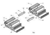
- Fig.1 shows a perspective view of the ends of two guide rails according to the present invention, with two alignment members ready to be driven into their respective alignment channels
- the guide rails 10, 12 are of identical form (i.e. they are identical in cross-section). Only the ends of the guide rails 10 and 12 are shown (as the invention relates only to the connection of those ends), but it will be understood that each guide rail 10, 12 can be of substantial length, for example 3 metres.
- the guide rails 10, 12 each comprise a channel section, with an opening 14.
- the opening 14 is sized to accommodate a part of a carriage (not shown), and in particular the part of the carriage which connects to a captive hinge (also not shown) of the folding/sliding door.
- the opening 14 is at the top of the guide rails, so that the guide rails 10,12 are oriented as required for fitting to the bottom of an opening (not shown) in the wall of a building. It will be understood that guide rails of identical form could be used at the top of the opening, with the opening 14 at the bottom of the guide rail, whereby to suspend the captive hinge(s) from the guide rails.
- the guide rails 10, 12 each have two pairs of guide ribs 16, 18. It will be understood that the carriage has a set of wheels or rollers which almost completely span the distance between the pairs of ribs, i.e. one wheel or roller lies between the left-hand rib 16 (as drawn) and the left-hand rib 18 and another wheel or roller lies between the right-hand rib 16 and the right-hand rib 18.
- the pair of guide ribs 16 support the wheels or rollers, and thereby support the carriage, in the guide rails such as 10 and 12 at the bottom of the opening, whereas the pair of guide ribs 18 support the wheels or rollers of the carriage in the corresponding guide rails at the top of the opening.
- guide ribs 16 and 18 are chosen to correspond to the design of the carriage of the folding/sliding door.
- Alternative designs of carriage, and correspondingly the alternative designs of guide rails for those carriages, can have a single guide rib 16 and 18, or more than two guide ribs.
- Another alternative design can include only the guide rib(s) 16 or the guide rib(s) 18, and yet another alternative design can have no guide ribs.
- the guide rails 10, 12 also include two alignment channels 20, 22 which are of a size and shape to accommodate a respective alignment member 24.
- the two alignment channels 20, 22 and also the two alignment members 24, are identical, but that need not be the case.
- the guide rails 10, 12 have two alignment channels 20, 22, more alignment channels can be provided if desired.
- the alignment members 24 are also of dovetail form, and are sized to be a tight fit into the alignment channels 20, 22. It is therefore necessary to drive each alignment member 24 into its respective alignment channel, such as by a hammer. Specifically, the two alignment members 24 can be driven into the alignment channels 20 and 22 of the guide rail 10 (or 12), and then the other guide rail 12 (or 10) can be driven thereonto by impacting the opposed end of that guide rail.
- the alignment members 24 preferably have a positioning rib, or a positioning projection, at or close to their longitudinal centre, the positioning rib or projection being too large to be driven into the alignment channel 20,22.
- the positioning rib or projection can therefore ensure that approximately half of the alignment member is located in the guide rail 10, and approximately half is located in the guide rail 12, in the assembled condition. Notwithstanding the presence of a positioning rib or projection, however, when assembled together it is arranged that the end 28 of the guide rail 12 abuts the end 30 of the guide rail 10, so that there is substantially no gap therebetween for the carriage to pass.
- the adjacent ends 28, 30 can be allowed to abut by including a recess in the end 28 and/or 30 to accommodate the positioning rib.
- the alignment channels 20, 22 and the alignment members 24 are of dovetail form so that the alignment channels can be open to the centre of the respective guide rail as shown. This avoids the requirement to make the alignment channels as closed channels (box sections), and thereby makes the guide rails 10, 12 easier to make as an extrusion.
- the alignment members 24 have tapered ends 32, 34, to facilitate their insertion into the alignment channels 20, 22.
- the alignment channels additionally or alternatively have flared ends for the same purpose.
- any misalignment of the guide ribs 16, 18 will be less than the misalignment of the alignment channels 20, 22. Since the alignment members can ensure almost perfect alignment of the guide rails 10 and 12, the guide ribs 16, 18 will also be substantially perfectly aligned, so that the passage of the carriage from one guide rail 10 to an adjacent guide rail 12 is imperceptible in practice.
- one of the guide ribs 16 and one of the guide ribs 18, is located to either side of the opening 14, and one of the alignment channels 20, 22 is located to either side of the four guide ribs.
- the alignment channel 20 when viewed from the end of a guide rail 10,12, from left to right, there is located the alignment channel 20, then a guide rail pair 16, 18, then the opening 14, then the other guide rail pair 16, 18, then the other alignment channel 22.
- guide rails of the invention are ideally suited to use with folding/sliding doors, similar guide rails may be used in other applications, such as for sliding patio doors for example.
Landscapes
- Engineering & Computer Science (AREA)
- Mechanical Engineering (AREA)
- Support Devices For Sliding Doors (AREA)
Applications Claiming Priority (1)
| Application Number | Priority Date | Filing Date | Title |
|---|---|---|---|
| GB201117042A GB201117042D0 (en) | 2011-10-04 | 2011-10-04 | Guide rail for a folding/sliding door |
Publications (2)
| Publication Number | Publication Date |
|---|---|
| EP2578785A2 true EP2578785A2 (de) | 2013-04-10 |
| EP2578785A3 EP2578785A3 (de) | 2015-04-15 |
Family
ID=45035078
Family Applications (1)
| Application Number | Title | Priority Date | Filing Date |
|---|---|---|---|
| EP12187217.0A Withdrawn EP2578785A3 (de) | 2011-10-04 | 2012-10-04 | Führungsschiene und Führungsschienenanordnung für eine Falt-/Schiebetür |
Country Status (2)
| Country | Link |
|---|---|
| EP (1) | EP2578785A3 (de) |
| GB (1) | GB201117042D0 (de) |
Cited By (4)
| Publication number | Priority date | Publication date | Assignee | Title |
|---|---|---|---|---|
| GB2560144A (en) * | 2016-11-17 | 2018-09-05 | Home Decor Gb Ltd | Modular track system |
| WO2020148432A1 (de) * | 2019-01-18 | 2020-07-23 | Hettich-Heinze Gmbh & Co. Kg | Schiebetürbeschlag und möbel |
| US11098512B2 (en) * | 2017-05-11 | 2021-08-24 | Julius Blum Gmbh | Guide system for guiding a furniture door |
| CN114207241A (zh) * | 2019-08-08 | 2022-03-18 | 海蒂诗-海因策有限及两合公司 | 滑动门配件、家具和用于组装滑动门配件的方法 |
Family Cites Families (4)
| Publication number | Priority date | Publication date | Assignee | Title |
|---|---|---|---|---|
| DE7528036U (de) * | 1975-09-05 | 1976-01-02 | Paul Hettich & Co, 4983 Kirchlengern | Fuehrungsbahnprofil eines schiebetuerbeschlages |
| ATE257541T1 (de) * | 1998-12-18 | 2004-01-15 | Peter Schmid | Laufschiene für ein schiebetor |
| DE202004003157U1 (de) * | 2004-02-26 | 2004-05-13 | Hettich-Heinze Gmbh & Co. Kg | Führungsschiene für Schiebe- oder Faltschiebetüren |
| DE202007009133U1 (de) * | 2007-06-29 | 2007-09-06 | Cardo Door Production Gmbh | Verbindungsstück zum Verbinden zweier Führungsschienen und Führungsschiene |
-
2011
- 2011-10-04 GB GB201117042A patent/GB201117042D0/en not_active Ceased
-
2012
- 2012-10-04 EP EP12187217.0A patent/EP2578785A3/de not_active Withdrawn
Non-Patent Citations (1)
| Title |
|---|
| None |
Cited By (8)
| Publication number | Priority date | Publication date | Assignee | Title |
|---|---|---|---|---|
| GB2560144A (en) * | 2016-11-17 | 2018-09-05 | Home Decor Gb Ltd | Modular track system |
| GB2560144B (en) * | 2016-11-17 | 2021-10-27 | Home Decor Gb Ltd | Modular track system |
| US11098512B2 (en) * | 2017-05-11 | 2021-08-24 | Julius Blum Gmbh | Guide system for guiding a furniture door |
| WO2020148432A1 (de) * | 2019-01-18 | 2020-07-23 | Hettich-Heinze Gmbh & Co. Kg | Schiebetürbeschlag und möbel |
| CN113227526A (zh) * | 2019-01-18 | 2021-08-06 | 海蒂诗-海因策有限及两合公司 | 滑动门配件和家具物品 |
| CN113227526B (zh) * | 2019-01-18 | 2023-04-04 | 海蒂诗-海因策有限及两合公司 | 滑动门配件和家具物品 |
| CN114207241A (zh) * | 2019-08-08 | 2022-03-18 | 海蒂诗-海因策有限及两合公司 | 滑动门配件、家具和用于组装滑动门配件的方法 |
| CN114207241B (zh) * | 2019-08-08 | 2023-12-15 | 海蒂诗-海因策有限及两合公司 | 滑动门配件、家具和用于组装滑动门配件的方法 |
Also Published As
| Publication number | Publication date |
|---|---|
| GB201117042D0 (en) | 2011-11-16 |
| EP2578785A3 (de) | 2015-04-15 |
Similar Documents
| Publication | Publication Date | Title |
|---|---|---|
| US20220170290A1 (en) | Fencing assembly | |
| US7677003B2 (en) | Integrated storm shutter including latch pin corner connection and/or center louver support rail | |
| US9856691B2 (en) | Sliding window assembly | |
| US9879471B2 (en) | Reinforced folding door and hinge assembly | |
| US9091119B2 (en) | Windows and doors assembly structure having a joint portion of 45 degrees | |
| US9453360B2 (en) | Window/ door system with flat track having “C”-shaped roller supports | |
| US7854248B2 (en) | Vision panel for movable partition, movable partitions and related methods | |
| US10156089B2 (en) | Fenestration supplement systems and methods of use | |
| US9470028B2 (en) | Sliding door assembly | |
| US8991099B1 (en) | Double acting patio door | |
| US20100012280A1 (en) | Folding door assembly | |
| KR101339951B1 (ko) | 고단열의 알루미늄 창호 프레임을 구비한 리프트 앤드 슬라이딩 시스템 창호 | |
| US20120023825A1 (en) | Watertight patio door assembly | |
| KR102794524B1 (ko) | 창호 체결 안전난간 장치 | |
| US20120047804A1 (en) | Self-storing vertical lift door system | |
| KR100917865B1 (ko) | 단열 외창 | |
| US20110203745A1 (en) | Louvered privacy screen for single- and double-hung sash windows | |
| KR101960480B1 (ko) | 경량과 단열이 향상된 창호 조립체 | |
| US20060240765A1 (en) | Closure device having ventilating structure | |
| KR101202127B1 (ko) | 구름 컨베이어를 갖는 창호 개폐 장치 | |
| EP3604725A1 (de) | Bruchfestes intelligentes schiebegehäuse | |
| KR101616317B1 (ko) | 3중 단열구조 미서기창 | |
| GB2571777A (en) | Secondary glazing for sash-type windows | |
| GB2506968A (en) | Bi-folding door with internal hinges | |
| KR101837518B1 (ko) | 이중 창호용 창틀 및 이를 포함하는 이중 창호 |
Legal Events
| Date | Code | Title | Description |
|---|---|---|---|
| PUAI | Public reference made under article 153(3) epc to a published international application that has entered the european phase |
Free format text: ORIGINAL CODE: 0009012 |
|
| AK | Designated contracting states |
Kind code of ref document: A2 Designated state(s): AL AT BE BG CH CY CZ DE DK EE ES FI FR GB GR HR HU IE IS IT LI LT LU LV MC MK MT NL NO PL PT RO RS SE SI SK SM TR |
|
| AX | Request for extension of the european patent |
Extension state: BA ME |
|
| PUAL | Search report despatched |
Free format text: ORIGINAL CODE: 0009013 |
|
| AK | Designated contracting states |
Kind code of ref document: A3 Designated state(s): AL AT BE BG CH CY CZ DE DK EE ES FI FR GB GR HR HU IE IS IT LI LT LU LV MC MK MT NL NO PL PT RO RS SE SI SK SM TR |
|
| AX | Request for extension of the european patent |
Extension state: BA ME |
|
| RIC1 | Information provided on ipc code assigned before grant |
Ipc: E05D 15/06 20060101AFI20150310BHEP |
|
| STAA | Information on the status of an ep patent application or granted ep patent |
Free format text: STATUS: THE APPLICATION IS DEEMED TO BE WITHDRAWN |
|
| 18D | Application deemed to be withdrawn |
Effective date: 20151016 |