EP2579079A1 - Optische kabelstruktur für eine lufgeblasene installation und herstellungsverfahren dafür - Google Patents
Optische kabelstruktur für eine lufgeblasene installation und herstellungsverfahren dafür Download PDFInfo
- Publication number
- EP2579079A1 EP2579079A1 EP11789166.3A EP11789166A EP2579079A1 EP 2579079 A1 EP2579079 A1 EP 2579079A1 EP 11789166 A EP11789166 A EP 11789166A EP 2579079 A1 EP2579079 A1 EP 2579079A1
- Authority
- EP
- European Patent Office
- Prior art keywords
- optical fiber
- optical cable
- optical
- sheath
- fiber unit
- Prior art date
- Legal status (The legal status is an assumption and is not a legal conclusion. Google has not performed a legal analysis and makes no representation as to the accuracy of the status listed.)
- Withdrawn
Links
- 230000003287 optical effect Effects 0.000 title claims abstract description 101
- 238000009434 installation Methods 0.000 title claims abstract description 19
- 238000004519 manufacturing process Methods 0.000 title claims abstract description 12
- 238000000034 method Methods 0.000 title claims description 8
- 239000013307 optical fiber Substances 0.000 claims abstract description 91
- 238000007664 blowing Methods 0.000 claims abstract description 44
- 229910052755 nonmetal Inorganic materials 0.000 claims abstract description 12
- 239000004760 aramid Substances 0.000 claims abstract description 5
- 229920003235 aromatic polyamide Polymers 0.000 claims abstract description 5
- 239000003365 glass fiber Substances 0.000 claims abstract description 3
- 238000001723 curing Methods 0.000 claims description 14
- 239000004033 plastic Substances 0.000 claims description 12
- 238000007639 printing Methods 0.000 claims description 12
- 239000011248 coating agent Substances 0.000 claims description 9
- 238000000576 coating method Methods 0.000 claims description 9
- 230000000694 effects Effects 0.000 claims description 9
- 239000011347 resin Substances 0.000 claims description 8
- 229920005989 resin Polymers 0.000 claims description 8
- 230000003014 reinforcing effect Effects 0.000 claims description 7
- 239000000126 substance Substances 0.000 claims description 7
- 239000004925 Acrylic resin Substances 0.000 claims description 6
- 238000004040 coloring Methods 0.000 claims description 6
- 235000015110 jellies Nutrition 0.000 claims description 5
- 239000008274 jelly Substances 0.000 claims description 5
- XLYOFNOQVPJJNP-UHFFFAOYSA-N water Substances O XLYOFNOQVPJJNP-UHFFFAOYSA-N 0.000 claims description 4
- 238000001816 cooling Methods 0.000 claims description 3
- 238000001035 drying Methods 0.000 claims description 3
- 238000000016 photochemical curing Methods 0.000 claims description 3
- 238000010276 construction Methods 0.000 abstract description 9
- 238000005299 abrasion Methods 0.000 description 5
- 238000004891 communication Methods 0.000 description 3
- 238000005516 engineering process Methods 0.000 description 2
- 239000000463 material Substances 0.000 description 2
- 230000009286 beneficial effect Effects 0.000 description 1
- 238000004364 calculation method Methods 0.000 description 1
- 230000007547 defect Effects 0.000 description 1
- 239000000835 fiber Substances 0.000 description 1
- 239000012530 fluid Substances 0.000 description 1
- 239000012535 impurity Substances 0.000 description 1
- QQONPFPTGQHPMA-UHFFFAOYSA-N propylene Natural products CC=C QQONPFPTGQHPMA-UHFFFAOYSA-N 0.000 description 1
- 125000004805 propylene group Chemical group [H]C([H])([H])C([H])([*:1])C([H])([H])[*:2] 0.000 description 1
- 238000004804 winding Methods 0.000 description 1
Images
Classifications
-
- G—PHYSICS
- G02—OPTICS
- G02B—OPTICAL ELEMENTS, SYSTEMS OR APPARATUS
- G02B6/00—Light guides; Structural details of arrangements comprising light guides and other optical elements, e.g. couplings
- G02B6/46—Processes or apparatus adapted for installing or repairing optical fibres or optical cables
- G02B6/50—Underground or underwater installation; Installation through tubing, conduits or ducts
- G02B6/52—Underground or underwater installation; Installation through tubing, conduits or ducts using fluid, e.g. air
-
- G—PHYSICS
- G02—OPTICS
- G02B—OPTICAL ELEMENTS, SYSTEMS OR APPARATUS
- G02B6/00—Light guides; Structural details of arrangements comprising light guides and other optical elements, e.g. couplings
- G02B6/04—Light guides; Structural details of arrangements comprising light guides and other optical elements, e.g. couplings formed by bundles of fibres
-
- G—PHYSICS
- G02—OPTICS
- G02B—OPTICAL ELEMENTS, SYSTEMS OR APPARATUS
- G02B6/00—Light guides; Structural details of arrangements comprising light guides and other optical elements, e.g. couplings
- G02B6/44—Mechanical structures for providing tensile strength and external protection for fibres, e.g. optical transmission cables
- G02B6/4479—Manufacturing methods of optical cables
- G02B6/4486—Protective covering
Definitions
- the invention relates to an optical cable structure suitable for air blowing installation and a manufacturing method thereof.
- the air blowing optical cable system is an optical cable installation technology by utilizing compressed air from an air compressor through blowing the optical fiber unit into an installed hollow pipe by an air blowing head.
- the optical cable is laid into the pipeline by the air blowing method. During the air blowing installation, air steams are used for pushing the optical cable to proceed along the pipeline.
- the optical cable is abraded by the inner wall of the pipeline and the impurities therein in the laying process.
- the printed letters on the surface of the optical cable can be abraded by the abrasion.
- an optical cable structure suitable for air blowing installation and the manufacturing method thereof are provided.
- the aims of air blowing distance and speed improvement are achieved through improving the structure of the outer surface of the optical cable for the optical cable structure, and the printed letters on the surface can be protected well.
- an optical cable structure suitable for air blowing installation comprises at least one optical fiber unit and a sheath coated on the optical fiber unit; at least one non-metal wire bundle is arranged between the sheath and the optical fiber unit; the adjacent part of the optical fiber unit comprises a reinforced rod and a filling rope; water-blocking substances are filled among the optical fiber unit, the reinforced rod and the filling rope; the optical fiber unit internally comprises at least one optical fiber; the surface of the sheath is provided with a plurality of convex or concave patterns; and letters are printed on the convex or concave patterns and between the convex or concave patterns, thus the printed letters can not be totally unclear because of abrasion; and the convex or concave patterns and the optical cable are in longitudinal and parallel arrangement, spiral arrangement with certain angle, or positive and reverse staggering spiral arrangement with certain angle.
- the optical fiber unit internally comprises at least one optical fiber, and the optical fiber unit comprises two configurations, the first configuration is that a loose buffer tube is coated on the optical fiber, and the loose buffer tube is filled with jelly; and the second configuration is that curing resin is coated on the optical fiber.
- At least one non-metal wire bundle is arranged between the sheath and the optical fiber unit, and comprises one or multiple of binding yarn, a tearing rope, aramid yarn and glass fiber yarn; the binding yarn is spirally wound on the optical fiber unit, and is used for binding and fixing a plurality of optical fiber units; the tearing rope and the sheath are in parallel arrangement; and the optical fiber unit is coated by the aramid yarn.
- the adjacent part of the optical fiber unit comprises a filling rope and a reinforced rod; the reinforced rod is used for reinforcing the stiffness of the optical cable; the outer diameter of the filling rope is the same with that of the optical fiber unit; and the filling rope surrounds the reinforced rod for ensuring the roundness of the cable core of the optical cable.
- Water-blocking substances are filled around the optical fiber unit, the reinforced rod and the filling rope for preventing external water substances osmosis from flowing into the optical cable.
- the manufacturing method of the optical cable suitable for air blowing installation comprising the following steps:
- the theory for improving the air blowing effect and increasing the air blowing distance for the invention is that supposing that the superficial area of a common air blowing optical cable in unit length is S1, and the cross section area is S2; the superficial area of the novel optical cable in the invention in unit length is S3, and the cross section area is S4, when the maximum outer diameters of two optical cables are same, we can come to the following conclusion that S1 ⁇ S3, and S2>S4, and the air blowing optical cable is mainly subjected to the effects of four forces:
- F1 represents the pushing force formed to the optical cable by a pneumatic motor driven air streams generated by an air compressor, when the output power of the air compressor is fixed, the pushing force is regarded as invariant.
- the generation of F2 is related to the air flow rate entering the pipeline and the frictional force generated at the surface of the micro pipe for the air steams. Because the cross section area S4 of the novel optical cable is less than the cross section area S3 of the common optical cable, when the power of the air compressor is fixed, the air stream rate entering the pipeline is relatively greater during the novel optical cable is laid.
- the surface of the novel optical cable has multiple concave surfaces, we can get that the superficial area S3 of the novel optical cable is greater than the superficial area S1 of the common optical cable, under the condition of same sheath material, the contact surface between the air streams and the surface of the novel optical cable is greater, furthermore, the air streams mentioned above are greater, the dragging force to the novel optical cable by the air streams is greater through the calculation of fluid mechanics. Additionally, because the surface of the novel optical cable has multiple concave grooves, when the air streams are acted on the concave grooves, not only is frictional force generated, and direct pushing force is generated because of the effect of component force, the novel optical cable can obtain greater air steam pushing force than the common optical cable in air blowing installation.
- F4 represents the resistance to the front end of the optical cable by the air pressure at the front of the pipeline, and is less related to the appearances of the two optical cables, but the air stream rate entering the pipeline by the air blowing machine can not be required to be increased too early when the air blowing begins, and additional resistance is avoided by the over-high air pressure in front when the optical cable is subjected to air blowing.
- optical cable structure suitable for air blowing installation and the manufacturing method thereof provided by the invention have the beneficial effects that the air blowing distance of the optical cable can be enhanced greatly, the construction period can be shortened, the construction cost can be lowered, and the printed letters on the surface can be protected effectively.
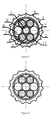
- the optical cable structure suitable for air blowing installation comprises at least one optical fiber unit (3) and a sheath (1) coated on the optical fiber unit (3);
- the optical fiber unit (3) internally comprises at least one optical fiber (4)and is also internally filled with jelly(7);
- the surface of the sheath (1) is provided with a plurality of convex or concave patterns, and letters are printed on the convex patterns and between the convex patterns, thus the printed letters can not be totally unclear because of abrasion;
- a non-metal wire bundle (2) is arranged between the sheath (1) and the optical fiber unit (3), and is formed by the winding of water-blocking binding yarn and a tearing rope;
- the binding yarn is spirally wound on the optical fiber unit (3);
- the tearing rope and the sheath (1) are in parallel arrangement;
- the adjacent part of the optical fiber unit (3) comprises a filling rope (6) and a reinforced rod (5); water-blocking substances (8) are arranged on the reinforced rod and are water-
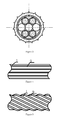
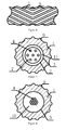
- the optical structure also can be a structure which is shown by figure (7 ), and is not provided with a reinforced rod (5), a filling rope (6) and water-blocking substances, and comprises an optical fiber unit and a sheath (1) coated on the optical fiber unit (3); the optical fiber unit (3) is internally provided with at least one optical fiber (4), and is also filled with jelly (7); the surface of the sheath (1) is provided with a plurality of convex or concave patterns (9); letters are printed on the convex patterns (9) and between the convex patterns (9), thus the printed letters can not be totally unclear because of abrasion; at least one non-metal wire bundle (2) is arranged between the sheath (1) and the optical fiber unit (3), and is a tearing rope.
- the optical structure also can be a structure shown by figure (8 ).
- Curing resin (10) is coated on the optical fiber (4);
- optical cable structure comprises an optical fiber unit (3) and a sheath coated on the optical fiber unit (3);
- the optical fiber unit (3) internally comprises at least one optical fiber (4);
- ultraviolet light curing acrylate resin (10) is coated on the optical fiber (4);
- the surface of the sheath is provided with a plurality of convex or concave patterns, and letters are printed on the convex patterns (9) and between the convex patterns (9), thus the printed letters can not be totally unclear because of abrasion.
- the manufacturing method of the optical cable suitable for air blowing installation comprising the following steps:
Landscapes
- Physics & Mathematics (AREA)
- General Physics & Mathematics (AREA)
- Optics & Photonics (AREA)
- Engineering & Computer Science (AREA)
- Manufacturing & Machinery (AREA)
- Light Guides In General And Applications Therefor (AREA)
- Optical Fibers, Optical Fiber Cores, And Optical Fiber Bundles (AREA)
Applications Claiming Priority (2)
| Application Number | Priority Date | Filing Date | Title |
|---|---|---|---|
| CN201020209794XU CN201698065U (zh) | 2010-05-31 | 2010-05-31 | 一种适合于气送敷设的光缆结构 |
| PCT/CN2011/074846 WO2011150787A1 (zh) | 2010-05-31 | 2011-05-30 | 一种适合于气送敷设的光缆结构及其制造方法 |
Publications (1)
| Publication Number | Publication Date |
|---|---|
| EP2579079A1 true EP2579079A1 (de) | 2013-04-10 |
Family
ID=43399312
Family Applications (1)
| Application Number | Title | Priority Date | Filing Date |
|---|---|---|---|
| EP11789166.3A Withdrawn EP2579079A1 (de) | 2010-05-31 | 2011-05-30 | Optische kabelstruktur für eine lufgeblasene installation und herstellungsverfahren dafür |
Country Status (4)
| Country | Link |
|---|---|
| EP (1) | EP2579079A1 (de) |
| KR (1) | KR20120086353A (de) |
| CN (4) | CN201698065U (de) |
| WO (1) | WO2011150787A1 (de) |
Cited By (5)
| Publication number | Priority date | Publication date | Assignee | Title |
|---|---|---|---|---|
| CN105589158A (zh) * | 2015-03-16 | 2016-05-18 | 沈群华 | 一种具有异型填充绳的光缆的制作方法 |
| EP3992685A1 (de) * | 2020-10-27 | 2022-05-04 | Sterlite Technologies Limited | Gaslecksicheres wellmanteldesign zur verminderung der reibung bei glasfaserkabeln |
| EP3796060B1 (de) | 2018-10-11 | 2022-12-28 | Fujikura Ltd. | Glasfaserkabel |
| EP4187298A1 (de) * | 2021-11-24 | 2023-05-31 | Sterlite Technologies Limited | Faseroptisches kabel für luftblasanlagen |
| EP4194914A4 (de) * | 2020-08-07 | 2024-07-24 | Fiberhome Telecommunication Technologies Co., Ltd | Luftgeblasenes glasfaserkabel |
Families Citing this family (35)
| Publication number | Priority date | Publication date | Assignee | Title |
|---|---|---|---|---|
| CN201698065U (zh) * | 2010-05-31 | 2011-01-05 | 四川汇源光通信有限公司 | 一种适合于气送敷设的光缆结构 |
| CN202649556U (zh) * | 2012-06-13 | 2013-01-02 | 烽火通信科技股份有限公司 | 一种高纤芯密度的气吹微型光缆 |
| CN103042839B (zh) * | 2013-01-27 | 2015-11-18 | 昆山信昌电线电缆有限公司 | 一种热塑性无卤阻燃材料喷码印字耐擦设备 |
| US9297975B2 (en) | 2013-07-19 | 2016-03-29 | Corning Optical Communications LLC | Optical fiber cable with print protective outer surface profile |
| CN103513377A (zh) * | 2013-09-27 | 2014-01-15 | 江苏亨通光电股份有限公司 | 超微型气吹光缆 |
| CA2959021C (en) * | 2014-08-22 | 2021-01-26 | Corning Optical Communications LLC | Optical fiber cable with print protective outer surface profile |
| CN105938230A (zh) * | 2016-07-01 | 2016-09-14 | 山东太平洋光纤光缆有限公司 | 一种新型高阻燃光缆 |
| CN106125242A (zh) * | 2016-08-29 | 2016-11-16 | 烽火通信科技股份有限公司 | 一种保护印字的扁平光缆 |
| CN106125241A (zh) * | 2016-08-30 | 2016-11-16 | 江苏中天科技股份有限公司 | 一种气吹用高强度微型色条光纤单元 |
| CN106094147A (zh) * | 2016-08-30 | 2016-11-09 | 江苏中天科技股份有限公司 | 一种气吹用高强度中心管式微型色条光缆 |
| CN109112861B (zh) * | 2017-06-26 | 2024-08-09 | 江苏海峰绳缆科技有限公司 | 一种可拼接式复合型船用绳缆 |
| CN107577020A (zh) * | 2017-10-27 | 2018-01-12 | 江苏法尔胜光通有限公司 | 加强微型气吹光纤单元及制造方法 |
| CN109228236A (zh) * | 2018-09-30 | 2019-01-18 | 深圳市普耐科技有限公司 | 一种曲线型挤出成型模具 |
| CN109228235A (zh) * | 2018-09-30 | 2019-01-18 | 深圳市普耐科技有限公司 | 一种直线型挤出成型模具 |
| CN109991709B (zh) * | 2019-03-29 | 2024-06-11 | 四川汇源光通信有限公司 | 一种适用于气吹敷设的光缆 |
| CN110286453A (zh) * | 2019-07-24 | 2019-09-27 | 南京华脉科技股份有限公司 | 一种引入光缆及制造方法 |
| CN110361822A (zh) * | 2019-08-10 | 2019-10-22 | 江苏俊知技术有限公司 | 一种新型结构的气吹光缆及其制造方法 |
| CN110850542A (zh) * | 2019-12-05 | 2020-02-28 | 深圳市特发信息光网科技股份有限公司 | 一种齿轮状中心管式拉远光缆及其制备方法 |
| CN114258503B (zh) * | 2019-12-11 | 2023-12-08 | 株式会社藤仓 | 光纤电缆 |
| CN111596427A (zh) * | 2020-05-29 | 2020-08-28 | 江苏中天科技股份有限公司 | 气吹微缆及其制备方法 |
| CN113838603B (zh) * | 2020-06-24 | 2023-05-16 | 华为技术有限公司 | 一种光电复合缆和通信系统 |
| CN111965776A (zh) * | 2020-09-04 | 2020-11-20 | 江苏亨通光电股份有限公司 | 一种螺旋微槽型气吹微缆、制造设备及制造方法 |
| CN113946023A (zh) * | 2021-10-11 | 2022-01-18 | 中天科技海缆股份有限公司 | 气吹光纤及导体内置测温光纤的阻水高压电缆 |
| CN113900205B (zh) * | 2021-10-26 | 2022-11-18 | 长飞光纤光缆股份有限公司 | 一种表面具有螺旋沟槽的水敷设光缆 |
| CN114779421B (zh) * | 2022-06-22 | 2022-09-30 | 长飞光纤光缆股份有限公司 | 一种防热冲击耐高压光缆 |
| CN115453699B (zh) * | 2022-10-31 | 2025-08-12 | 长飞光纤光缆(上海)有限公司 | 一种锯齿形光电气吹缆 |
| CN116009161A (zh) * | 2022-12-20 | 2023-04-25 | 长飞光纤光缆股份有限公司 | 一种气吹光纤束光缆及其制备方法 |
| CN115616723B (zh) * | 2022-12-20 | 2023-03-31 | 长飞光纤光缆股份有限公司 | 一种气吹光缆及其制造方法 |
| CN115877525A (zh) * | 2022-12-20 | 2023-03-31 | 长飞光纤光缆股份有限公司 | 一种气吹光纤束光缆制备装置 |
| CN116125610A (zh) * | 2022-12-23 | 2023-05-16 | 汕头高新区奥星光通信设备有限公司 | 一种可降低光缆风压的光缆制备方法 |
| CN116626832A (zh) * | 2023-06-27 | 2023-08-22 | 烽火通信科技股份有限公司 | 一种可双向施工气吹光缆及制造方法 |
| CN119758546B (zh) * | 2024-09-27 | 2026-01-30 | 烽火通信科技股份有限公司 | 一种层绞式气吹微缆 |
| CN119861459B (zh) * | 2025-03-25 | 2025-07-15 | 江苏中天科技股份有限公司 | 一种气吹光缆 |
| CN119861458A (zh) * | 2025-03-25 | 2025-04-22 | 江苏中天科技股份有限公司 | 一种气吹光缆及其生产工艺 |
| CN120611534B (zh) * | 2025-08-07 | 2025-10-31 | 江苏中天科技股份有限公司 | 气吹光缆的凸齿数量设计方法及气吹光缆 |
Family Cites Families (28)
| Publication number | Priority date | Publication date | Assignee | Title |
|---|---|---|---|---|
| JPH0754367B2 (ja) * | 1987-01-23 | 1995-06-07 | 住友電気工業株式会社 | 光フアイバユニツト |
| GB8911959D0 (en) * | 1988-05-28 | 1989-07-12 | Ici Plc | Coated optical fibres |
| JP3113297B2 (ja) * | 1991-03-01 | 2000-11-27 | 昭和電線電纜株式会社 | 光ファイバユニット |
| CA2110800C (en) * | 1991-07-01 | 2000-10-24 | Philip Alfred Barker | Optical fibres |
| SE513107C2 (sv) * | 1998-11-05 | 2000-07-10 | Ericsson Telefon Ab L M | Förfarande och anordning för att installera optofiberkabelelement |
| SE9900623L (sv) * | 1999-02-22 | 2000-06-26 | Ericsson Telefon Ab L M | Anordning för matning av optofiber |
| US20020136509A1 (en) * | 1999-12-13 | 2002-09-26 | Watson Fraser Murray | Laying of a cable within a duct |
| CN1720474A (zh) * | 2003-01-07 | 2006-01-11 | Lg电线有限公司 | 适于空气喷吹安装的光纤单元及其制造方法 |
| GB0305276D0 (en) * | 2003-03-07 | 2003-04-09 | British Telecomm | Optical cable |
| KR100511891B1 (ko) * | 2003-04-11 | 2005-09-02 | 엘에스전선 주식회사 | 유체 역류방지 수단을 구비한 광섬유 유닛 포설장치 |
| CN1225666C (zh) * | 2003-04-25 | 2005-11-02 | 江苏中天科技股份有限公司 | 微束型紧包光纤单元及其制作方法 |
| KR100528751B1 (ko) * | 2003-06-27 | 2005-11-15 | 엘에스전선 주식회사 | 윤활성 표면을 갖는 광섬유 유닛 포설용 튜브 |
| CN1580847A (zh) * | 2003-08-11 | 2005-02-16 | 长飞光纤光缆(上海)有限公司 | 微型光缆网络的施工方法 |
| CN2684213Y (zh) * | 2003-12-01 | 2005-03-09 | 江苏亨通光电股份有限公司 | 超柔微型气送光缆 |
| CN2667514Y (zh) * | 2004-01-05 | 2004-12-29 | 江苏亨通光电股份有限公司 | 综合光缆气送管道 |
| WO2006025812A1 (en) * | 2004-07-16 | 2006-03-09 | Charles Glew | Hollow support separators for communications cable |
| CN2775693Y (zh) * | 2004-12-22 | 2006-04-26 | 江苏亨通光电股份有限公司 | 室外用非金属加强抗潮大芯数气送管道光缆 |
| CN201051168Y (zh) * | 2007-06-10 | 2008-04-23 | 成都亨通光通信有限公司 | 一种用于接入网的新型气送微缆 |
| CN201051167Y (zh) * | 2007-06-10 | 2008-04-23 | 成都亨通光通信有限公司 | 层绞式大芯数气送光缆 |
| CN201075144Y (zh) * | 2007-07-26 | 2008-06-18 | 江苏永鼎股份有限公司 | 微型气送光纤单元 |
| CN201199274Y (zh) * | 2008-04-24 | 2009-02-25 | 长飞光纤光缆(上海)有限公司 | 一种全介质中心束管式气吹微型光缆 |
| CN201278033Y (zh) * | 2008-06-07 | 2009-07-22 | 江苏亨通光电股份有限公司 | 一种外表面具有玻璃微珠层的气送光纤单元 |
| CN201210189Y (zh) * | 2008-06-07 | 2009-03-18 | 江苏亨通光电股份有限公司 | 双护套微型气送光纤单元 |
| CN201281772Y (zh) * | 2008-06-07 | 2009-07-29 | 江苏亨通光电股份有限公司 | 微型半紧套气送光纤单元 |
| CN201425633Y (zh) * | 2009-05-05 | 2010-03-17 | 长飞光纤光缆有限公司 | 一种光纤束单元 |
| CN201698065U (zh) * | 2010-05-31 | 2011-01-05 | 四川汇源光通信有限公司 | 一种适合于气送敷设的光缆结构 |
| CN101915972A (zh) * | 2010-07-03 | 2010-12-15 | 蒋菊生 | 防收缩光缆及其制造方法 |
| CN101950059A (zh) * | 2010-08-18 | 2011-01-19 | 江苏长飞中利光纤光缆有限公司 | 层绞式光缆及其制备方法和方法所用的装置 |
-
2010
- 2010-05-31 CN CN201020209794XU patent/CN201698065U/zh not_active Expired - Lifetime
-
2011
- 2011-05-28 CN CN2011101405054A patent/CN102183830A/zh active Pending
- 2011-05-28 CN CN2011101405073A patent/CN102183832A/zh active Pending
- 2011-05-28 CN CN2011101405069A patent/CN102183831A/zh active Pending
- 2011-05-30 WO PCT/CN2011/074846 patent/WO2011150787A1/zh not_active Ceased
- 2011-05-30 KR KR1020127015582A patent/KR20120086353A/ko not_active Ceased
- 2011-05-30 EP EP11789166.3A patent/EP2579079A1/de not_active Withdrawn
Non-Patent Citations (1)
| Title |
|---|
| See references of WO2011150787A1 * |
Cited By (6)
| Publication number | Priority date | Publication date | Assignee | Title |
|---|---|---|---|---|
| CN105589158A (zh) * | 2015-03-16 | 2016-05-18 | 沈群华 | 一种具有异型填充绳的光缆的制作方法 |
| EP3796060B1 (de) | 2018-10-11 | 2022-12-28 | Fujikura Ltd. | Glasfaserkabel |
| US12105335B2 (en) | 2018-10-11 | 2024-10-01 | Afl Telecommunications Llc | Optical fiber cable |
| EP4194914A4 (de) * | 2020-08-07 | 2024-07-24 | Fiberhome Telecommunication Technologies Co., Ltd | Luftgeblasenes glasfaserkabel |
| EP3992685A1 (de) * | 2020-10-27 | 2022-05-04 | Sterlite Technologies Limited | Gaslecksicheres wellmanteldesign zur verminderung der reibung bei glasfaserkabeln |
| EP4187298A1 (de) * | 2021-11-24 | 2023-05-31 | Sterlite Technologies Limited | Faseroptisches kabel für luftblasanlagen |
Also Published As
| Publication number | Publication date |
|---|---|
| WO2011150787A1 (zh) | 2011-12-08 |
| CN102183832A (zh) | 2011-09-14 |
| CN102183830A (zh) | 2011-09-14 |
| KR20120086353A (ko) | 2012-08-02 |
| CN102183831A (zh) | 2011-09-14 |
| CN201698065U (zh) | 2011-01-05 |
Similar Documents
| Publication | Publication Date | Title |
|---|---|---|
| EP2579079A1 (de) | Optische kabelstruktur für eine lufgeblasene installation und herstellungsverfahren dafür | |
| CN102023357A (zh) | 全干式大芯数气吹微缆及光纤束加工方法 | |
| KR100584952B1 (ko) | 공기압 포설용 광섬유 유닛 및 그 제조방법 | |
| CN202119952U (zh) | 表面具有凹凸纹槽的绞合式微型气吹光缆 | |
| CN111965776A (zh) | 一种螺旋微槽型气吹微缆、制造设备及制造方法 | |
| CN107797206A (zh) | 高密度光纤束微单元光缆的生产设备及其生产方法 | |
| CN105467539A (zh) | 一种非金属层绞结构光缆 | |
| CN202453564U (zh) | 一种微型易分歧布线光缆 | |
| CN107577020A (zh) | 加强微型气吹光纤单元及制造方法 | |
| CN110549579A (zh) | 一种挤塑成型装置及光缆圆整度提升工艺 | |
| CN202110314U (zh) | 表面具有凹凸纹槽的强化气吹光纤单元 | |
| CN103587019B (zh) | 一种光纤束的成型设备及其成型方法 | |
| CN112034571A (zh) | 一种抗收缩多单元平行束管光缆及其制造方法 | |
| CN1239936C (zh) | 信号传输缆及其制造方法 | |
| CN212694131U (zh) | 一种抗收缩多单元平行束管光缆 | |
| CN209784609U (zh) | 一种高灵敏传感光纤单元 | |
| CN201974551U (zh) | 全干式多芯数气吹光缆 | |
| CN112630912A (zh) | 层绞式气吹微缆及其生产设备、加工方法 | |
| CN116107048B (zh) | 全干式光缆的光单元生产系统、方法及全干式光缆 | |
| CN110142942B (zh) | 一种气吹微缆微套管超高速二次套塑生产设备及工艺 | |
| KR100633905B1 (ko) | 공기압 포설용 광섬유 유닛, 그 제조방법 및 장치 | |
| CN209803414U (zh) | 一种适用于气吹敷设的光缆 | |
| CN106584721B (zh) | 一种加热固化装置 | |
| CN207586487U (zh) | 加强微型气吹光纤单元 | |
| CN212781424U (zh) | 一种适用于狭小空间布放的气吹微缆 |
Legal Events
| Date | Code | Title | Description |
|---|---|---|---|
| PUAI | Public reference made under article 153(3) epc to a published international application that has entered the european phase |
Free format text: ORIGINAL CODE: 0009012 |
|
| 17P | Request for examination filed |
Effective date: 20120404 |
|
| AK | Designated contracting states |
Kind code of ref document: A1 Designated state(s): AL AT BE BG CH CY CZ DE DK EE ES FI FR GB GR HR HU IE IS IT LI LT LU LV MC MK MT NL NO PL PT RO RS SE SI SK SM TR |
|
| DAX | Request for extension of the european patent (deleted) | ||
| STAA | Information on the status of an ep patent application or granted ep patent |
Free format text: STATUS: THE APPLICATION IS DEEMED TO BE WITHDRAWN |
|
| 18D | Application deemed to be withdrawn |
Effective date: 20151201 |