EP2579082A1 - Optisches bildformungssystem und bildaufnahmevorrichtung - Google Patents
Optisches bildformungssystem und bildaufnahmevorrichtung Download PDFInfo
- Publication number
- EP2579082A1 EP2579082A1 EP11786521.2A EP11786521A EP2579082A1 EP 2579082 A1 EP2579082 A1 EP 2579082A1 EP 11786521 A EP11786521 A EP 11786521A EP 2579082 A1 EP2579082 A1 EP 2579082A1
- Authority
- EP
- European Patent Office
- Prior art keywords
- lens
- optical system
- image
- imaging optical
- negative
- Prior art date
- Legal status (The legal status is an assumption and is not a legal conclusion. Google has not performed a legal analysis and makes no representation as to the accuracy of the status listed.)
- Withdrawn
Links
Images


Classifications
-
- G—PHYSICS
- G02—OPTICS
- G02B—OPTICAL ELEMENTS, SYSTEMS OR APPARATUS
- G02B27/00—Optical systems or apparatus not provided for by any of the groups G02B1/00 - G02B26/00, G02B30/00
- G02B27/0025—Optical systems or apparatus not provided for by any of the groups G02B1/00 - G02B26/00, G02B30/00 for optical correction, e.g. distorsion, aberration
-
- G—PHYSICS
- G02—OPTICS
- G02B—OPTICAL ELEMENTS, SYSTEMS OR APPARATUS
- G02B13/00—Optical objectives specially designed for the purposes specified below
- G02B13/06—Panoramic objectives; So-called "sky lenses" including panoramic objectives having reflecting surfaces
-
- G—PHYSICS
- G02—OPTICS
- G02B—OPTICAL ELEMENTS, SYSTEMS OR APPARATUS
- G02B13/00—Optical objectives specially designed for the purposes specified below
- G02B13/16—Optical objectives specially designed for the purposes specified below for use in conjunction with image converters or intensifiers, or for use with projectors, e.g. objectives for projection TV
Definitions
- the present invention relates to an imaging optical system and an image-acquisition apparatus.
- the optical systems described in PTL 1 to PTL 3 and PTL 6 have an angle of view that is unsatisfactory for installing them in endoscopes and be used for internal diagnosis. That is, with such optical systems, it is difficult to thoroughly examine inside the body, which has three-dimensional structures with depressions and protrusions; for example, it is difficult to examine the back side of an intestinal fold.
- a front group of the optical systems described in PTL 4 and PTL 5 contains one negative lens. Thus, to achieve negative power, the curvature of the negative lens must be set extremely large, making the negative lens difficult to manufacture and causing the lens diameter to increase due to the inability to move the entrance pupil position toward the object side.
- the present invention has been conceived in consideration of the above-described situation, and an object of the present invention is to provide an imaging optical system and an image acquisition apparatus that can be suitably used in a small-diameter endoscope, even when the angle of view is extremely wide.
- a first aspect of the present invention is an imaging optical system including a negative front group; an aperture stop; and a positive rear group, in this order from the object side, wherein the front group contains, in order from the object side, a negative first lens and a negative second lens, and the rear group includes a cemented lens formed by joining together at least three lenses.
- the number of lenses that constitute each group can be reduced, the entire length can be reduced, and manufacturing costs can be reduced. Since the front group contains negative first and second lenses, the principal point of the front group is positioned on the object side. In this way, it is possible to have a wide-angle lens configuration as well as a small first lens diameter, which tends to be large in a wide-angle lens configuration, thus making realizing a narrow-diameter optical system.
- the rear group has a cemented lens that is formed by joining together at least three lenses, on-axis and off-axis chromatic aberrations can be corrected satisfactorily. Moreover, by using a cemented lens, it is possible to directly fix the lenses together without using a frame; therefore, axial displacement of the lenses in the rear group can be effectively prevented, and its influence on aberrations due to relative decentering of the lenses can be suppressed.
- a second aspect of the present invention is an imaging optical system including a negative front group; an aperture stop; and a positive rear group, in this order from the object side, wherein the front group contains, in order from the object side, a negative first lens and a negative second lens, and the rear group includes a cemented lens formed by joining together at least a positive lens and a negative lens, wherein the half angle of view is 100° or larger. In this aspect, it is more preferable that the half angle of view be 110° or larger.
- the total length and manufacturing costs can be reduced, and on-axis and off-axis chromatic aberrations can be satisfactorily corrected by disposing a cemented lens which is formed by joining together two lenses in the rear group.
- the first lens preferably satisfies conditional expression (1) below 1.6 ⁇ nd ⁇ 1 ⁇ 2.4 where nd1 represents the index of refraction at the d line of the first lens.
- Conditional expression (1) relates to the first lens.
- the index of refraction of the first lens falls below the lower limit of conditional expression (1) because the curvature of the object-side surface of the first lens would have to be significantly increased to prevent total reflection when the incident angle of a light beam is large, causing the lens diameter to be large. It is undesirable if the index of refraction of the first lens exceeds the upper limit of conditional expression (1) because manufacturing or procurement of the lens would become difficult and costs would soar.
- a third aspect of the present invention is an imaging optical system including a negative front group; an aperture stop; and a positive rear group, in this order from the object side, wherein the front group contains, in order from the object side, a negative first lens and a negative second lens, and the rear group includes a cemented lens formed by joining together at least a positive lens and a negative lens, wherein conditional expression (1) below is satisfied: 1.6 ⁇ nd ⁇ 1 ⁇ 2.4 where nd1 represents the index of refraction at the d line of the first lens L1.
- the half angle of view be 110° or larger.
- the compound lens in the rear group, may be disposed closest to the image, and the compound lens may be formed by joining a positive lens, a negative lens, and a positive lens, in this order from the object side.
- the cemented lens which is composed of three lenses, closest to the image in the optical system where the light rays separate, off-axis chromatic aberration, in particular, can be satisfactorily corrected.
- spherical aberration and comatic aberration can be satisfactorily corrected.
- the rear group may include at least two positive lenses and a cemented lens formed by joining together a positive lens, a negative lens, and a positive lens, in this order from the object side.
- the cemented lens may satisfy conditional expression (2) below: 0.5 ⁇ Pw ⁇ 5 / Pw ⁇ 7 ⁇ 3.0 where Pw5 represents a refractive power of a positive lens disposed closest to the object among the lenses composing the cemented lens, and Pw7 represents a refractive power of a positive lens disposed closest to the image among the lenses composing the cemented lens.
- Conditional expression (2) is associated with the power arrangement of the cemented lens. If the power ratio of the positive lenses is within the range of conditional expression (2), the positive power can be sufficiently distributed between the positive lenses, and thus, chromatic aberration, spherical aberration, and comatic aberration can be satisfactorily corrected. It is undesirable if the power ratio is not in the range of conditional expression (2) because the power would be biased to one of the positive lenses, and various types of aberrations would be more likely to occur.
- the cemented lens may satisfy conditional expressions (3) and (4) below: 30 ⁇ ⁇ r ⁇ 5 - ⁇ r ⁇ 6 ⁇ 80 and 20 ⁇ ⁇ r ⁇ 7 - ⁇ r ⁇ 6 ⁇ 80
- ⁇ r5 represents the Abbe number of a positive lens disposed closest to the object among the lenses composing the cemented lens
- vr6 represents the Abbe number of a negative lens among the lenses composing the cemented lens
- ⁇ r7 represents the Abbe number of a positive lens disposed closest to the image among the lenses composing the cemented lens.
- Conditional expressions (3) and (4) are associated with the achromatic effect of the cemented lens. If the relationship between the Abbe numbers of the lenses satisfies conditional expressions (3) and (4), the cemented lens will have a sufficient chromatic aberration correction effect. It is undesirable if the relationship between the Abbe numbers of the lenses falls below the lower limits of conditional expressions (3) and (4) because it would become difficult to achieve a sufficient achromatic effect, and on-axis and off-axis chromatic aberrations would occur. It is undesirable if the relationship between the Abbe numbers of the lenses exceeds the upper limits of the conditional expression (3) and (4) because it would be difficult to obtain glass materials.
- the first lens may satisfy conditional expression (5) below: 1.0 ⁇ r ⁇ 1 + r ⁇ 2 / r ⁇ 1 - r ⁇ 2 ⁇ 5.0 where r1 represents the radius of curvature of the object-side surface of the first lens, and r2 represents the radius of curvature of the image-side surface of the first lens.
- Conditional expression (5) is associated with the shape factor of the first lens. If the radius of curvature of each surface of the first lens satisfies conditional expression (5), negative power can be achieved while maintaining a wide angle of view and not causing total reflection. It is undesirable if the relationship between the radii of curvature of the surfaces of the first lens falls below the lower limit of conditional expression (5) because the diameter of the first lens would increase, and total reflection would be more likely to occur with a wide angle of view. It is undesirable if the relationship between the radii of curvature of the surfaces of the first lens exceeds the upper limit of conditional expression (5) because the ease of manufacture of the first lens would decrease significantly.
- the second lens may satisfy conditional expression (6) below: 0.5 ⁇ r ⁇ 3 + r ⁇ 4 / r ⁇ 3 - r ⁇ 4 ⁇ 6.0 where r3 represents the radius of curvature of the object-side surface of the second lens, and r4 represents the radius of curvature of the image-side surface of the second lens.
- Conditional expression (6) is associated with the shape factor of the second lens. If the radii of curvature of the surfaces of the second lens satisfy conditional expression (6), sufficient negative power is achieved while suppressing, in particular, off-axis aberration. If the relationship between the radii of curvature of surfaces of the second lens exceeds the upper limit of conditional expression (6), it is undesirable because sufficient negative power of the second lens would not be achieved, and the optical system would become very large because the principal point would move toward the image side.
- the front group may satisfy conditional expression (7) below: 0.2 ⁇ Pw ⁇ 1 / Pw ⁇ 2 ⁇ 2.0 where Pw1 represents a refractive power of the first lens, and Pw2 represents a refractive power of the second lens.
- Conditional expression (7) is associated with the power arrangement of the front group. If the power ratio of the lenses is within the range defined by conditional expression (7), the lens diameter can be decreased while maintaining a wide angle of view. It is undesirable if the power ratio of the lenses exceeds the upper limit of conditional expression (7) because the power of the first lens would become too large, making it difficult to maintain a wide angle of view and making, in particular, off-axis aberration more likely to occur. It is undesirable if the power ratio of the lenses falls below the lower limit of conditional expression (7) because the second lens would become too large, making off-axis aberration more likely to occur and causing the first lens to become very large.
- a fourth aspect of the present invention is an image acquisition apparatus comprising the imaging optical system according to above-described first to third aspects; an image acquisition unit configured to acquire an optical image formed by the imaging optical system and to convert the acquired optical image to a digital image; and an image processing unit configured to generate a corrected image by subjecting the digital image acquired by the image acquisition unit to image processing for correcting aberration in the digital image.
- corrected images with electrically corrected barrel distortion which tends to occur in particular at the wide-angle end as the angle of view is widened, can be recorded or displayed.
- a fifth aspect of the present invention is an image acquisition apparatus comprising the imaging optical system according to the above-described first to third aspects; an image acquisition unit configured to acquire an optical image formed by the imaging optical system and to convert the acquired optical image to a digital image; and a correction circuit configured to electrically correct chromatic aberration of magnification of the digital image acquired by the image acquisition unit. According to the fifth aspect of the present invention, it is possible to acquire a satisfactory image by electrically correcting chromatic aberration of magnification in an optical image formed by the imaging optical system.
- the present invention is advantageous in that it can be suitably employed in a small-diameter endoscope while having a sufficiently wide angle of view, and manufacturing costs can be reduced.
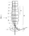
- the imaging optical system 1 includes, in order from the object side, a negative front group FG, an aperture stop S, and a positive back group BG.
- the front group FG contains a negative first lens L1 and a negative second lens L2.
- the first lens L1 and the second lens L2 are meniscus lenses each having a convex surface facing the object side.
- the back group BG contains, in order from the object side, a positive third lens L3, a positive fourth lens L4, a parallel plate F, and a positive cemented lens CL.
- the third lens L3 is a positive meniscus lens having a convex surface facing the image side.
- the fourth lens L4 is a plano-convex lens having a convex surface facing the object side.
- the cemented lens CL is formed by bonding together three lenses: a fifth lens L5, which is a biconvex lens having the surface with the larger curvature facing the image side; a sixth lens L6, which is a biconcave lens; and a seventh lens L7, which is a biconvex lens having the surface with the larger curvature facing the object side.
- the parallel plate F is a filter that blocks light of a particular wavelength, such as 1060 nm light of a YAG laser, 810 nm light of a semiconductor laser, or light in the near-infrared region.
- An image acquisition device 2 is disposed near the image plane.
- Reference characters CG represent a cover glass provided to protect the image acquisition surface of the image acquisition device.
- the imaging optical system according to this embodiment can be combined with the image acquisition device 2 for use in an optical system for endoscopes and digital cameras.
- the first lens L1 satisfies conditional expression (1): 1.6 ⁇ nd ⁇ 1 ⁇ 2.4
- nd1 represents the index of refraction at the d line of the first lens L1.
- the index of refraction nd1 of the first lens L1 preferably satisfies 1.9 ⁇ nd1 ⁇ 2.4 and more preferably satisfies 2.1 ⁇ nd1 ⁇ 2.4.
- the cemented lens CL satisfies conditional expression (2) : 0.5 ⁇ Pw ⁇ 5 / Pw ⁇ 7 ⁇ 3.0
- Pw5 represents the power of the fifth lens L5
- Pw7 represents the power of the seventh lens L7.
- the power values Pw5 and Pw7 of the fifth and seventh lenses L5 and L7 preferably satisfy 1.0 ⁇ Pw5/Pw7 ⁇ 2.0 and, more preferably, satisfy 1.2 ⁇ Pw5/Pw7 ⁇ 1.8.
- the cemented lens CL satisfies conditional expressions (3) and (4): 30 ⁇ ⁇ r ⁇ 5 - ⁇ r ⁇ 6 ⁇ 80 and 20 ⁇ ⁇ r ⁇ 7 - ⁇ r ⁇ 6 ⁇ 80
- ⁇ r5 represents the Abbe number of the fifth lens L5
- vr6 represents the Abbe number of the sixth lens L6
- ⁇ r7 represents the Abbe number of the seventh lens L7.
- the Abbe numbers ⁇ r5, ⁇ r6, and vr7 of the lenses L5, L6, and L7 preferably satisfy 33 ⁇ ⁇ r5- ⁇ r6 ⁇ 70 and 21 ⁇ ⁇ r7- ⁇ r6 ⁇ 70 and, more preferably, satisfy 35 ⁇ ⁇ r5- ⁇ r6 ⁇ 60 and 21.5 ⁇ ⁇ r7- ⁇ r6 ⁇ 60.
- the first lens L1 satisfies conditional expression (5): 1.0 ⁇ r ⁇ 1 + r ⁇ 2 / r ⁇ 1 - r ⁇ 2 ⁇ 5.0
- r1 represents the radius of curvature of the object-side surface of the first lens L1
- r2 represents the radius of curvature of the image-side surface of the first lens L1.
- the radii of curvature r1 and r2 of the surfaces of the first lens L1 preferably satisfy 1.5 ⁇ (r1+r2)/(r1-r2) ⁇ 3.0 and, more preferably satisfy 2.0 ⁇ (r1+r2)/(r1-r2) ⁇ 2.3.
- the second lens L2 satisfies conditional expression (6): 0.5 ⁇ r ⁇ 3 + r ⁇ 4 / r ⁇ 3 - r ⁇ 4 ⁇ 6.0
- r3 represents the radius of curvature of the object-side surface of the second lens L2
- r4 represents the radius of curvature of the image-side surface of the second lens L2.
- the radii of curvature r3 and r4 of the surfaces of the second lens L2 preferably satisfy 0.8 ⁇ (r3+r4)/(r3-r4) ⁇ 3.0 and, more preferably, satisfy 1.1 ⁇ (r3+r4)/(r3-r4) ⁇ 1.3.
- the first lens L1 and the second lens L2 satisfy conditional expression (7): 0.2 ⁇ Pw ⁇ 1 / Pw ⁇ 2 ⁇ 2.0 where Pw1 represents the power value of the first lens L1, and Pw2 represents the power value of the second lens L2.
- the power values Pw1 and Pw2 of the first lens L1 and second lens L2 preferably satisfy 0.2 ⁇ Pw1/Pw2 ⁇ 1.0 and, more preferably, satisfy 0.3 ⁇ Pw1/Pw2 ⁇ 0.6.
- the imaging optical system 1 configured as described above, even with a ultra-wide angle of view, the diameter of the first lens L1, which tends to increase in particular as the angle of view is widened, can be set small. Therefore, there is an advantage in that it can be appropriately installed in a small-diameter endoscope, such as a gastroenterological endoscope. Also, there are advantages in that sites that are difficult to sufficiently examine with known endoscopes, such as the back side of an intestinal fold, can be easily examined, and diagnostic accuracy using endoscopic images can be improved.
- the imaging optical system 1 can be installed in an image acquisition apparatus.
- the image acquisition apparatus includes, for example, in order from the object side, the imaging optical system 1, the image acquisition (image acquisition unit) device 2, a correction circuit, and an image processing unit.
- the image acquisition device 2 is, for example, a CCD and converts an optical image formed by the imaging optical system 1 to a digital image.
- the correction circuit carries out processing for correcting chromatic aberration of magnification of the digital image acquired by the image acquisition device.
- the image processing unit carries out image processing for correcting distortion in the digital image that has been corrected at the correction circuit.
- the image acquisition device 2 installed in, for example, an endoscope or an electronic still camera
- the image of an object is separated into three primary-color images, i.e., a first primary-color image, a second primary-color image, and a third primary-color image, and then a color image is reproduced by superposing the output signals of the three colors computationally.
- the imaging optical system 1 has chromatic aberration of magnification, the position where the image is formed by light of the second and third primary colors is displaced from the position where the image is formed by light of the first primary color, with reference to the image formed by the first primary color.
- the displacement amount of the position where the images formed by light of the second and third primary colors with respect to the position where the image formed by the light of the first primary color should be calculated in advance for the picture elements in the image acquisition device 2 on the basis of the aberration information of the optical system. Then, coordinate transformation is performed on each pixel of the acquired image so as to correct the displacement amount between the first primary color and the second and third primary colors.
- the displacement in the imaging positions of R and B relative to the imaging position of G is calculated for each pixel, coordinate transformation of the R and B images is performed to cancel out the calculated displacement, and then, the coordinate-transformed images are superposed with the G image.
- the surface number represents the number of the optical surface as counted from the object side
- the index of refraction represents the index of refraction at the d line
- the unit of the radius of curvature and the spacing between surfaces is mm.
- r1, r2, r3,... respectively represent the optical surfaces having surface numbers 1, 2, 3,...
- d1, d2, d3,... respectively represent the inter-surface spacing, or air space, of the surfaces having surface numbers 1, 2, 3,...
- the arrow X represents the object surface.
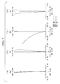
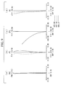
- (a) represents spherical aberration
- (b) represents astigmatism
- (c) represents distortion
- (d) represents chromatic aberration of magnification.
- the horizontal axes represent the aberration (mm), except for that of distortion, and the unit of wavelength is nm.
- the imaging optical system according to this example contains, in order from the object side, a negative front group, an aperture stop, and a positive back group.
- the front group contains, in order from the object side, a negative meniscus lens having a convex surface facing the object side and a negative meniscus lens having a convex surface facing the object side.
- the back group includes, in order from the object side, a positive meniscus lens having a convex surface facing the image side, a positive lens having a convex surface facing the image side, a parallel plate, and a positive cemented lens.
- the cemented lens is formed by bonding together three lenses, in order from the object side: a biconvex lens having the surface with the larger curvature facing the image side, a biconcave lens, and a biconvex lens having the surface with the larger curvature facing the object side.
- the imaging optical system according to this example satisfies conditional expressions (1) to (7).
- the aberration diagram for the imaging optical system according to this example having the above-described configuration is illustrated in Fig. 3 .
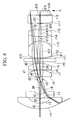
- a lens sectional view of an imaging optical system according to Example 2 of the present invention is illustrated in Fig. 4 , and the corresponding lens data is listed below.
- the configuration of the back group of the imaging optical system according to this example differs from that according to Example 1.
- the back group contains, in order from the object side, a plano-convex lens having a convex surface facing the image side, a plano-convex lens having a convex surface facing the image side, a parallel plate, and a positive cemented lens.
- the cemented lens is formed by bonding together three lenses, in order from the object side: a biconvex lens (positive lens) having the surface with the larger curvature facing the image side, a biconcave lens (negative lens), and a biconvex lens (positive lens) having the surface with the larger curvature facing the image side.
- the imaging optical system according to this example satisfies conditional expressions (1) to (7).
- the aberration diagram for the imaging optical system according to this Example, configured as described above, is illustrated in Fig. 5 .
- a lens sectional view of an imaging optical system according to Example 3 of the present invention is illustrated in Fig. 6 , and the corresponding lens data is listed below.
- the configuration of the back group of the imaging optical system according to this example differs from that according to Example 1.
- the back group contains, in order from the object side, a plano-convex lens having a convex surface facing the image side, a first positive cemented lens, a parallel plate, and a second positive cemented lens.
- the first positive cemented lens is formed by bonding together, in order from the object side, a plano-convex lens having a convex surface facing the image side and a negative meniscus lens having a convex surface facing the image side.
- the second positive cemented lens is formed by bonding together, in order from the object side, a biconvex lens (positive lens) having the surface with the larger curvature facing the image side and a biconcave lens (negative lens).
- the imaging optical system according to this example satisfies conditional expressions (1) and (5) to (7).
- the aberration diagram for the imaging optical system according to this Example, configured as described above, is illustrated in Fig. 7 .
- a lens sectional view of an imaging optical system according to Example 4 of the present invention is illustrated in Fig. 8 , and the corresponding lens data is listed below.
- the configuration of the back group of the imaging optical system according to this example differs from that according to Example 1.
- the back group contains, in order from the object side, a plano-convex lens having a convex surface facing the image side, a plano-convex lens having a convex surface facing the image side, a plano-convex lens having a convex surface facing the image side, a parallel plate, and a positive cemented lens.
- the positive cemented lens is formed by bonding together, in order from the object side, a biconvex lens (positive lens) having the surface with the larger curvature facing the image side and a biconcave lens (negative lens).
- the imaging optical system according to this example satisfies conditional expressions (1) and (5) to (7).
- the aberration diagram for the imaging optical system according to this Example, configured as described above, is illustrated in Fig. 9 .
- a lens sectional view of an imaging optical system according to Example 5 of the present invention is illustrated in Fig. 10 , and the corresponding lens data is listed below.
- the configuration of the back group of the imaging optical system according to this example differs from that according to Example 1.
- the back group contains, in order from the object side, a positive meniscus lens having a convex surface facing the image side, a plano-convex lens having a convex surface facing the image side, a parallel plate, and a positive cemented lens.
- the cemented lens is formed by bonding together three lenses, in order from the object side: a biconvex lens (positive lens) having the surface with the larger curvature facing the image side, a biconcave lens (negative lens), and a biconvex lens (positive lens) having the surface with the larger curvature facing the image side.
- the imaging optical system according to this Example satisfies conditional expressions (1) to (7).
- the aberration diagram for the imaging optical system according to this Example, configured as described above, is illustrated in Fig. 11 .
- Example 1 Example 2
- Example 3 Example 4
- Example 5 fb 0.89 1.35 1.35 1.35 0.84
- Total length 6.26 8.75 8.75 8.75 6.13 View of angle 110.5 116.7 116.7 116.5 110.0
- Total system focal length 0.30 0.59 0.57 0.57 0.30 Image height 0.47 0.91 0.91 0.91 0.47
Landscapes
- Physics & Mathematics (AREA)
- General Physics & Mathematics (AREA)
- Optics & Photonics (AREA)
- Lenses (AREA)
Applications Claiming Priority (2)
| Application Number | Priority Date | Filing Date | Title |
|---|---|---|---|
| JP2010122845 | 2010-05-28 | ||
| PCT/JP2011/061269 WO2011148822A1 (ja) | 2010-05-28 | 2011-05-17 | 結像光学系および撮像装置 |
Publications (2)
| Publication Number | Publication Date |
|---|---|
| EP2579082A1 true EP2579082A1 (de) | 2013-04-10 |
| EP2579082A4 EP2579082A4 (de) | 2017-10-25 |
Family
ID=45003813
Family Applications (1)
| Application Number | Title | Priority Date | Filing Date |
|---|---|---|---|
| EP11786521.2A Withdrawn EP2579082A4 (de) | 2010-05-28 | 2011-05-17 | Optisches bildformungssystem und bildaufnahmevorrichtung |
Country Status (5)
| Country | Link |
|---|---|
| US (1) | US8331041B2 (de) |
| EP (1) | EP2579082A4 (de) |
| JP (1) | JP5006476B2 (de) |
| CN (1) | CN102713718B (de) |
| WO (1) | WO2011148822A1 (de) |
Cited By (3)
| Publication number | Priority date | Publication date | Assignee | Title |
|---|---|---|---|---|
| EP2662718A4 (de) * | 2011-10-06 | 2013-12-18 | Olympus Medical Systems Corp | Optisches system für ein endoskop |
| US12181632B2 (en) | 2018-12-05 | 2024-12-31 | Sony Semiconductor Solutions Corporation | Imaging device and imaging apparatus |
| TWI885683B (zh) * | 2024-01-04 | 2025-06-01 | 國立中央大學 | 耦合透鏡組 |
Families Citing this family (21)
| Publication number | Priority date | Publication date | Assignee | Title |
|---|---|---|---|---|
| JP6304962B2 (ja) * | 2013-07-26 | 2018-04-04 | キヤノン株式会社 | 光学系及びそれを有する撮像装置 |
| US9488804B2 (en) * | 2013-08-08 | 2016-11-08 | Genius Electronic Optical Co., Ltd. | Optical imaging lens |
| US9638889B2 (en) * | 2014-03-24 | 2017-05-02 | Sintai Optical (Shenzhen) Co., Ltd. | Lens assembly |
| US9857569B2 (en) * | 2014-10-31 | 2018-01-02 | Everready Precision Ind. Corp. | Combined lens module and image capturing-and-sensing assembly |
| WO2016190184A1 (ja) | 2015-05-28 | 2016-12-01 | オリンパス株式会社 | 内視鏡対物光学系 |
| JP6460934B2 (ja) | 2015-07-22 | 2019-01-30 | 富士フイルム株式会社 | 撮像レンズおよび撮像装置 |
| JP6426063B2 (ja) | 2015-07-22 | 2018-11-21 | 富士フイルム株式会社 | 撮像レンズおよび撮像装置 |
| CN108761743B (zh) | 2016-07-13 | 2020-10-02 | 浙江舜宇光学有限公司 | 七片式广角镜头 |
| DE112017004856T5 (de) | 2016-09-28 | 2019-06-13 | Olympus Corporation | Endoskop-Objektivoptik |
| CN107884913B (zh) * | 2016-09-30 | 2020-05-19 | 日本电产三协株式会社 | 广角镜头 |
| EP3598192B1 (de) * | 2018-01-26 | 2021-11-17 | SZ DJI Technology Co., Ltd. | Weitwinkelobjektiv, bildgebungsvorrichtung und unbemanntes luftfahrzeug |
| JP7141018B2 (ja) * | 2018-10-12 | 2022-09-22 | コニカミノルタ株式会社 | 光学系、レンズユニット、及び撮像装置 |
| CN109445077B (zh) * | 2019-01-10 | 2021-10-29 | 宁波舜宇车载光学技术有限公司 | 光学镜头及成像设备 |
| CN109984718B (zh) * | 2019-02-25 | 2021-03-23 | 浙江大学 | 一种超大视场内窥镜物镜 |
| CN111123479B (zh) * | 2020-01-17 | 2025-10-10 | 东莞市宇瞳光学科技股份有限公司 | 一种光学镜头 |
| CN114077028A (zh) * | 2020-08-21 | 2022-02-22 | 宁波舜宇光电信息有限公司 | 直立式变焦模组及相应的拍摄方法 |
| CN112162388B (zh) * | 2020-11-03 | 2022-06-07 | 福建福光股份有限公司 | 一种大相对孔径大视场的日盲紫外光学系统 |
| CN113946040B (zh) * | 2021-11-11 | 2024-11-05 | 厦门力鼎光电股份有限公司 | 一种紧凑型超广角镜头 |
| TWI813196B (zh) | 2022-03-09 | 2023-08-21 | 大立光電股份有限公司 | 成像光學系統鏡組、取像裝置及電子裝置 |
| CN115281581B (zh) * | 2022-08-23 | 2025-09-02 | 安徽七色光医疗科技有限公司 | 一种硬管光学显微内窥镜及其物镜 |
| KR20240054099A (ko) * | 2022-10-18 | 2024-04-25 | 엘지이노텍 주식회사 | 광학계 및 카메라 모듈 |
Family Cites Families (20)
| Publication number | Priority date | Publication date | Assignee | Title |
|---|---|---|---|---|
| US5424877A (en) | 1992-04-10 | 1995-06-13 | Olympus Optical Co., Ltd. | Observation optical system for endoscopes |
| JPH05288986A (ja) * | 1992-04-10 | 1993-11-05 | Olympus Optical Co Ltd | 内視鏡用観察光学系 |
| JPH06292207A (ja) * | 1993-04-02 | 1994-10-18 | Sony Corp | 撮像装置 |
| JPH09224180A (ja) * | 1996-02-15 | 1997-08-26 | Matsushita Electric Ind Co Ltd | 撮像装置 |
| JPH10260348A (ja) * | 1997-03-19 | 1998-09-29 | Fuji Photo Optical Co Ltd | 内視鏡用対物レンズ |
| JP3295027B2 (ja) | 1997-10-17 | 2002-06-24 | 株式会社マーク | レトロフォーカス型大口径比広角レンズ |
| JP4111470B2 (ja) | 1998-02-27 | 2008-07-02 | フジノン株式会社 | 広角ズームレンズ |
| JP2005181993A (ja) * | 2003-11-28 | 2005-07-07 | Sekinosu Kk | 投影レンズ |
| JP4705770B2 (ja) | 2004-08-26 | 2011-06-22 | オリンパス株式会社 | 接合レンズを備えた光学系及びそれを用いた撮像装置 |
| JP2007017528A (ja) | 2005-07-05 | 2007-01-25 | Nikon Corp | ズームレンズ |
| JP2007148137A (ja) | 2005-11-29 | 2007-06-14 | Kyocera Corp | 変倍撮像レンズ、光学モジュール、および携帯端末 |
| JP4869096B2 (ja) * | 2006-02-14 | 2012-02-01 | 富士フイルム株式会社 | 内視鏡用対物レンズ |
| JP2008151904A (ja) | 2006-12-15 | 2008-07-03 | Olympus Corp | 広角光学系 |
| JP4964578B2 (ja) | 2006-12-20 | 2012-07-04 | 富士フイルム株式会社 | 内視鏡用対物レンズ |
| JP4949871B2 (ja) | 2007-01-22 | 2012-06-13 | 富士フイルム株式会社 | 撮像レンズ、および該撮像レンズを備えた撮像装置 |
| JP2008281857A (ja) | 2007-05-11 | 2008-11-20 | Largan Precision Co Ltd | ズームレンズ |
| JP5167724B2 (ja) * | 2007-08-21 | 2013-03-21 | 株式会社ニコン | 光学系 |
| US7817347B2 (en) | 2007-08-30 | 2010-10-19 | Olympus Imaging Corp. | Zoom lens and imaging apparatus incorporating the same |
| JP2009128654A (ja) * | 2007-11-26 | 2009-06-11 | Sony Corp | 魚眼系撮像レンズ |
| JP2009134175A (ja) * | 2007-11-30 | 2009-06-18 | Olympus Imaging Corp | 結像光学系 |
-
2011
- 2011-05-17 CN CN2011800065744A patent/CN102713718B/zh active Active
- 2011-05-17 EP EP11786521.2A patent/EP2579082A4/de not_active Withdrawn
- 2011-05-17 JP JP2011550344A patent/JP5006476B2/ja not_active Expired - Fee Related
- 2011-05-17 WO PCT/JP2011/061269 patent/WO2011148822A1/ja not_active Ceased
- 2011-11-30 US US13/307,540 patent/US8331041B2/en not_active Expired - Fee Related
Cited By (3)
| Publication number | Priority date | Publication date | Assignee | Title |
|---|---|---|---|---|
| EP2662718A4 (de) * | 2011-10-06 | 2013-12-18 | Olympus Medical Systems Corp | Optisches system für ein endoskop |
| US12181632B2 (en) | 2018-12-05 | 2024-12-31 | Sony Semiconductor Solutions Corporation | Imaging device and imaging apparatus |
| TWI885683B (zh) * | 2024-01-04 | 2025-06-01 | 國立中央大學 | 耦合透鏡組 |
Also Published As
| Publication number | Publication date |
|---|---|
| US8331041B2 (en) | 2012-12-11 |
| JP5006476B2 (ja) | 2012-08-22 |
| CN102713718A (zh) | 2012-10-03 |
| EP2579082A4 (de) | 2017-10-25 |
| CN102713718B (zh) | 2013-07-17 |
| WO2011148822A1 (ja) | 2011-12-01 |
| JPWO2011148822A1 (ja) | 2013-07-25 |
| US20120133802A1 (en) | 2012-05-31 |
Similar Documents
| Publication | Publication Date | Title |
|---|---|---|
| US8331041B2 (en) | Imaging optical system and image-acquisition apparatus | |
| JP6501810B2 (ja) | 撮像レンズ | |
| US7773318B2 (en) | Objective optical system for endoscopes | |
| EP2477053B1 (de) | Optisches objektivsystem für ein endoskop | |
| US8243129B2 (en) | Objective lens and endoscope apparatus | |
| EP2336815B1 (de) | Vierlinsiges Retrofokusobjektiv und Abbildungsvorrichtung | |
| US8449127B2 (en) | Endoscope objective lens and endoscope using the same | |
| EP2299306A1 (de) | Optisches weitwinkelsystem und bildgebungsvorrichtung | |
| US11543647B2 (en) | Objective optical system for endoscope, endoscope, and image pickup unit | |
| EP2706391A1 (de) | Optische einheit und endoskop | |
| CN109416459B (zh) | 内窥镜物镜光学系统 | |
| WO2012008312A1 (ja) | 対物光学系 | |
| US10488635B2 (en) | Image pickup apparatus | |
| US11903560B2 (en) | Objective optical system, image pickup apparatus, endoscope and endoscope system | |
| WO2017216969A1 (ja) | 明るいリレー光学系及びそれを用いた硬性鏡用光学系、硬性鏡 | |
| US10842360B2 (en) | Objective optical system | |
| JP2018138983A (ja) | 撮像装置 | |
| JP4373749B2 (ja) | 撮像光学系、内視鏡用撮像装置及び内視鏡システム | |
| CN219552748U (zh) | 摄像系统、内窥镜物镜及内窥镜 | |
| JP6764813B2 (ja) | 対物光学系及び内視鏡 | |
| US20230273404A1 (en) | Objective optical system, image pickup apparatus, and endoscope | |
| US11933961B2 (en) | Stereoscopic vision endoscope objective optical system and endoscope using the same | |
| JP6987668B2 (ja) | 内視鏡用対物光学系 | |
| WO2016114082A1 (ja) | 対物レンズ及びそれを備えた撮像装置 | |
| CN117826369A (zh) | 摄像系统、内窥镜物镜及内窥镜 |
Legal Events
| Date | Code | Title | Description |
|---|---|---|---|
| PUAI | Public reference made under article 153(3) epc to a published international application that has entered the european phase |
Free format text: ORIGINAL CODE: 0009012 |
|
| 17P | Request for examination filed |
Effective date: 20120619 |
|
| AK | Designated contracting states |
Kind code of ref document: A1 Designated state(s): AL AT BE BG CH CY CZ DE DK EE ES FI FR GB GR HR HU IE IS IT LI LT LU LV MC MK MT NL NO PL PT RO RS SE SI SK SM TR |
|
| DAX | Request for extension of the european patent (deleted) | ||
| RAP1 | Party data changed (applicant data changed or rights of an application transferred) |
Owner name: OLYMPUS CORPORATION |
|
| RAP1 | Party data changed (applicant data changed or rights of an application transferred) |
Owner name: OLYMPUS CORPORATION |
|
| RAP1 | Party data changed (applicant data changed or rights of an application transferred) |
Owner name: OLYMPUS CORPORATION |
|
| RIN1 | Information on inventor provided before grant (corrected) |
Inventor name: KATAKURA, MASAHIRO Inventor name: KAMO, YUJI Inventor name: TAKATO, HIDEYASU |
|
| RA4 | Supplementary search report drawn up and despatched (corrected) |
Effective date: 20170927 |
|
| RIC1 | Information provided on ipc code assigned before grant |
Ipc: H04N 5/225 20060101ALI20170921BHEP Ipc: G02B 13/04 20060101AFI20170921BHEP |
|
| STAA | Information on the status of an ep patent application or granted ep patent |
Free format text: STATUS: THE APPLICATION HAS BEEN WITHDRAWN |
|
| 18W | Application withdrawn |
Effective date: 20171228 |