EP2579226A2 - Testeur de détecteur de chaleur - Google Patents
Testeur de détecteur de chaleur Download PDFInfo
- Publication number
- EP2579226A2 EP2579226A2 EP12186987.9A EP12186987A EP2579226A2 EP 2579226 A2 EP2579226 A2 EP 2579226A2 EP 12186987 A EP12186987 A EP 12186987A EP 2579226 A2 EP2579226 A2 EP 2579226A2
- Authority
- EP
- European Patent Office
- Prior art keywords
- heat detector
- temperature
- housing
- switch
- test
- Prior art date
- Legal status (The legal status is an assumption and is not a legal conclusion. Google has not performed a legal analysis and makes no representation as to the accuracy of the status listed.)
- Withdrawn
Links
Images

Classifications
-
- G—PHYSICS
- G08—SIGNALLING
- G08B—SIGNALLING SYSTEMS, e.g. PERSONAL CALLING SYSTEMS; ORDER TELEGRAPHS; ALARM SYSTEMS
- G08B29/00—Checking or monitoring of signalling or alarm systems; Prevention or correction of operating errors, e.g. preventing unauthorised operation
- G08B29/12—Checking intermittently signalling or alarm systems
- G08B29/14—Checking intermittently signalling or alarm systems checking the detection circuits
- G08B29/145—Checking intermittently signalling or alarm systems checking the detection circuits of fire detection circuits
Definitions
- the present invention relates to a device for testing a heat detector. More specifically, the present invention relates to a device for testing heat detectors that are located at various locations including those within a user's reach and those high above the floor, such that they cannot be easily reached.
- Heat detectors exist on the market including those that measure a fixed temperature and those that measure the rate of temperature rise.
- Fixed temperature heat detectors are designed to activate a visual and/or audible alarm after a fixed temperature is reached during a slow heat rise.
- Rate of rise heat detectors sense rapid changes in the temperature in the surrounding air and when a certain change threshold is met will activate an alarm.
- fixed temperature and rate of temperature rise heat detectors can be installed as separate devices, they are also available in a single device.
- heat detectors come in myriad sizes and shapes. Some heat detectors exhibit a more traditional semi-circular shape and, when mounted, hang close to the ceiling or wall, while other heat detectors are more rectangular in shape and hang down from the ceiling when mounted.
- a device for testing a heat detector should therefore be lightweight, durable, adaptable, reliable, easy to use, and provide necessary information to its operator or user.
- the present invention seeks to improve upon the prior art through the use of an improved design for a device for testing heat detectors that enables efficient testing by providing a portable, lightweight device that can be used to test heat detectors of varying shapes, sizes, and locations and by providing a read out that can be recorded to check that the heat detector that is being tested has functioned properly.
- a device for testing a heat detector comprises a housing shaped to receive a heat detector.
- a heating element is carried by the housing, and a fan is located proximate to the heater and adapted to activate the heat detector by increasing a temperature around the heat detector.
- the device also comprises a temperature device that is carried by the housing that measures the temperature near the heat detector.
- a display is attached to the housing that shows a value that relates to the temperature.
- a device for testing a heat detector comprises a housing shaped to receive a heat detector.
- a heating element is carried by the housing and adapted to activate the heat detector by increasing a temperature around the heat detector.
- a temperature device is also carried by the housing that measures the temperature near the heat detector.
- a memory is carried by the housing for storing a value related to the temperature.
- the device further comprises a test switch carried by the housing, wherein a change of state of the test switch causes the value to be stored in the memory.
- a method of testing a heat detector using a device comprises a housing shaped to receive a heat detector, a heating element carried by the housing and adapted to activate the heat detector by increasing a temperature around the heat detector, a temperature device carried by the housing that measures the temperature near the heat detector, a display attached to the housing that shows a value that relates to the temperature, a start switch carried by the housing, and a test switch carried by the housing, wherein a change of state of the test switch freezes the value shown on the display.
- the method comprises the step of moving the device toward the heat detector to be tested until a testing position is reached, wherein the housing of the device substantially surrounds the heat detector in the testing position and wherein the heating element is activated by the start switch upon contact of the start switch with an object.
- the method also comprises the step of maintaining the device in the testing position until the heat detector is activated.
- the method further comprises the step of moving the housing away from the heat detector once the heat detector is activated to change the state of the test switch, whereby changing the state of the test switch freezes the value shown on the display.
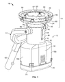
- FIG. 1 is an isometric view of a device for testing a heat detector
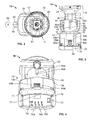
- FIG. 2 is a top view of the device of FIG. 1 ;
- FIG. 3 is a front view of the device of FIG. 1 , with the device in an extended position;
- FIG. 4 is a bottom and back slanted view of the device of FIG. 1 ;
- FIG. 5 is a left side elevational view of the device of FIG. 1 ; the right side being essentially a mirror image thereof; and
- FIG. 6 is a cross-sectional view of the device along the lines 6-6 of FIG. 5 .
- the device 10 includes a housing 12, which is comprised of a testing chamber 14, a body 16, battery compartments 18a and 18b, and a base 20. Also shown in FIG. 1 is a handle 22, which is connected to the body 16.
- the testing chamber 14 comprises a cup 24, which is frusto-conical in shape, and a cylindrical neck 26.
- the testing chamber 14 is attached to the body 16 via the neck 26.
- the cup 24 and the neck 26 guide the device 10 over the heat detector being tested to an optimal testing position, in which the testing chamber 14 surrounds the heat detector creating a close-fit between the heat detector being tested and the testing chamber 14.
- the cup 24 and the neck 26 can be made of a durable, transparent material to enable a user to observe the heat detector during testing and see any visual alarms associated with the heat detector.
- the cup 24 and the neck 26 can be made from a durable, non-transparent material.
- the testing chamber 14 also includes a removable lid 28, which is attached to the upper edge of the cup 24, distal to the neck 26.
- the lid 28 is placed on the device 10 when heat detectors of a smaller diameter are to be tested. When heat detectors having a larger diameter are to be tested, the lid 28 can be removed. It is preferred that the lid 28 is made of a flexible, heat resistant, non-conductive material such as silicone rubber or Santoprene® so that a firm seal can be created around the heat detector without the user having to exert a lot of pressure to the device 10. A firm seal is important to prevent the loss of heat generated by the device 10 during testing.
- the body 16 of the device 10 comprises an upper section 30 and a lower section 32.
- the upper section 30 is generally cylindrical in shape and the lower section 32 is generally rectangular in shape although any shape can be used so long as the body 16 and the neck 26 have similar shapes.
- the body 16 is hollow and suitably sized to carry the neck 26 of the testing chamber 14, as well as a heating element 34 and a fan 36 (shown in FIG. 6 ), both of which will be discussed in more detail below.
- the body 16 is preferably constructed from a durable, light-weight, heat resistant, and non-conductive material such as nylon, polypropylene, or acrylonitrile butadiene styrene.
- the upper section 30 has an inner surface (not shown).
- Protrusions 38 provided on the neck 26 create a friction fit with the inner surface of the upper section 30.
- the friction fit of the protrusions 38 and the inner surface of the upper section 30 is such that the testing chamber 14 is able to slide from a compact position as shown in FIG. 1 to an extended position as shown in FIG. 3 and vice versa.
- channels 40 between each of the protrusions 38 are channels 40.
- the channels 40 enable room-temperature air and excess heat to escape the device 10 during use.
- a stopping mechanism may be provided such as a ledge on the inner side of the upper section 30 and an annular protrusion (not shown) on the bottom of the neck 26 to prevent the neck 26 from being removed from the body 16.
- the upper section 30 also includes a front side 42, which contains an elongated aperture 44.
- An adjuster slide 46 which is carried by the neck 26, fits within the elongated aperture 44.
- the adjustor slide 46 enables a user to select between the compact or extended positions, by moving the adjustor slide 46 along the elongated aperture 44. It is preferable that the adjustor slide 46 contain a mechanical clicking mechanism that enables the neck 26 to be held in place at various points along the elongated aperture 44 to accommodated heat detectors of varying heights.
- an electronic switch is also contemplated.
- the elongated aperture 44 has an upside-down L-shape.
- the adjuster slide 46 is moved vertically up the elongated aperture 44 and then pushed to the side to lock the neck 26 in the extended position.
- a second elongated aperture 44a and a second adjuster slide 46a also may be included on a back side 48 of the neck 26 as shown in FIG. 4 , to provide added stability and support to the testing chamber 14 when in the extended position.
- the upper section 30 further includes ears 50a and 50b.
- the ears 50a, 50b are located on corresponding left and right sides 52a and 52b, respectively, of the upper section 30.
- the handle 22 is attached to the ears 50a, 50b with pins 54a and 54b (shown in FIG. 6 ) and extends behind the back side 48 of the upper section 30.
- the pins 54a, 54b can be held in place by any suitable mechanical connection mechanism known to those skilled in the art.
- the housing 12 is movable about a horizontal axis that extends through the midpoints of the ears 50a and 50b, thus enabling the housing 12 to be positioned in numerous locations relative to the handle 22.
- the handle 22 comprises a U-shaped portion 56 and a connection tail 58.
- the connection tail 58 is attached to the U-shaped portion 56 at a midpoint 60.
- the lower part of the U-shaped portion 56 and the connection tail 58 may be positioned at a downward angle of approximately 135 degrees from the upper part of the U-shaped portion 56.
- the angle and shape of the handle may vary or contain a hinge.
- the housing 12 be able to lock at a specific position relative to the handle 22. This can be accomplished by including a locking mechanism, ratchet mechanism, or rotary damper.
- An extension device 62 may be attached to the handle 22 through the connection tail 58 to enable a user to test heat detectors that are in a remote location, e.g., out of reach of the user.
- the extension device 62 is ideally made out of a lightweight, non-conductive material such as fiberglass and adjustable to enable a user to test heat detectors at varying heights from the floor.
- the lower section 32 comprises left and right portions 64a and 64b, respectively. Attached to the left and right portions 64a, 64b are the battery compartments 18a and 18b, which house standard sized batteries. The battery compartment 18a is attached to the left portion 64a and the battery compartment 18b is attached to the right portion 64b. The battery compartments 18a, 18b also comprise battery base portions 66a and 66b, respectfully.
- the power source i.e., batteries
- the device 10 enables the device 10 to be quickly mounted on different extension devices for the testing of heat detectors at varying heights and locations. Furthermore, although two battery compartments are provided, the device 10 only requires one battery to operate. The use of a single battery reduces the weight of the device 10, thereby further improving the efficiency of testing high mounted detectors.
- the base 20 Attached to the battery base portions 66a, 66b, and an underside portion 68 of the body 16 is the base 20.
- the base 20 has a generally recta-cylindrical shape and is constructed from material similar to or the same as that used for the body 16.
- On a bottom 70 of the base 20 are a display 72, power switch 74, mode switches 76a, 76b, 76c, and a test start button 78.
- the display 72 includes one or more light emitting diodes or LEDs, which are connected by any suitable electronics known by those skilled in the art. LEDs that correspond with the mode switches 76a, 76b, 76c may also be included to provide the user with a visual indication as to which mode they have selected.
- the display 72 provides the user with the measurement of the temperature taken by a temperature device 80 (shown in FIG. 2 ), which is preferably housed within the body 16.
- the temperature device 80 can be an infrared thermometer, thermocouple, or other suitable temperature measuring device.
- the ability to display the temperature measurement while testing is critical in determining whether the heat detector is operating properly.
- the location of the display 72 on the bottom 70 of the base 20 enables the user to observe the temperature measurements displayed during testing.
- the display 72 may also provide the user with additional information including battery life, type of test being performed, e.g., rate to rise/fixed temperature or high/low temperature test, the date, and time.
- the power switch 74 turns the device 10 on and off.
- the power switch 74 When the power switch 74 is activated, power is provided to the display 72, the mode switches 76a, 76b, 76c, the test start button 78, the temperature device 80, and the various LEDs and electronics contained within the device.
- the test start button 78 is pressed by a user before a test is conducted to clear the information from a previous test shown on the display and/or stored in a memory 82, which is discussed in more detail below.
- the test start button 78 is connected to the heating element 34 and the fan 36 via a control board 83 (shown in FIG. 6 ) and, upon actuation of the test start button 78, power is provided to the heating element 34, the fan 36, and a start switch 86 (shown in FIGS. 1 and 6 ).
- Mode switch 76a allows a user to choose between a fixed temperature test mode and a rate of temperature rise test mode.
- Mode switch 76b enables a user to select whether the test is to be performed at a high or low temperature
- mode switch 76c enables a user to choose the desired temperature unit, i.e., Fahrenheit (F) or Celsius (C), at which the test is to be performed and displayed.
- F Fahrenheit
- C Celsius
- a user can use one device, device 10, to test two different types of heat detectors or to test two different functions within one heat detector, thereby saving time and money.
- the ability to select a high or low temperature test is desirable because it enables two different categories of heat detector to be tested-one category grouped around 135 degrees F and one category grouped around 200 degrees F.
- multiple mode switches are discussed, a single multi-mode switch can be used.
- the device 10 may contain a single, combined power/mode switch.
- the control board 83 When a fixed temperature test is selected by the user, the control board 83 is programmed to monitor the temperature of the air around the heat detector and adjust power to the heating element 34 and the fan 36 to maintain a desired or maximum temperature for a period of time. For example, if a low temperature test is selected, the control board 83 will regulate the heating element 34 and the fan 36 such that when a maximum temperature of 150 degrees F is reached, that temperature is maintained for approximately 20 seconds. Similarly, if a high temperature test is selected, the control board 83 will adjust the power to the heating element 34 and the fan 36 so that once a maximum temperature of 200 degrees F is reached, it is maintained for several seconds.
- the ability to reach and maintain a maximum temperature is beneficial and an important improvement because some heat detectors do not actuate immediately, i.e., as soon as the air around the detector is heated to a specific temperature. Rather, some heat detectors require the heating of the entire heat detector itself before actuation will occur, which requires more time and exposure to the heated air. If the temperature is not monitored and the heating element 34 and the fan 36 are not regulated, the temperature of the heated air produced by the heating element and directed by the fan will continue to rise, which may cause internal and/or external portions of the heat detector to melt or become damaged in some way. Therefore, by programming the control board 83 to regulate the heating element 34 and the fan 36 such that a specific temperature is reached and maintained, damage to the internal and external portions of the heat detector can be prevented.
- FIG. 6 is a cross-sectional view of the device 10 taken along the line 6-6.
- the heating element 34 may be a positive thermal coefficient (PCT) ceramic heating element, an open coil heater, or similar heating device.
- PCT heating element is used such as a Cirrus 40/2 Fan Heater manufactured by DBK David + Baader GmbH.
- the fan 36 is disposed on one side of the heating element 34 and the nozzle 85 is located on a different side.
- the fan 36 may be located below the heating element 34 and the nozzle 85 may be located above the heating element 34.
- the fan 36 blows air through the heating element 34, which heats the air, and the nozzle 85 further directs the heated air at the heat detector being tested.
- the use of the fan 36 is important because it provides for efficient testing of the heat detector by blowing the heated air directly at the heat detector.
- the start switch 86 may be disposed on an inner rim 87 of cup 24 as shown in FIGS. 1 and 6 , or attached to the exterior of the housing 12.
- the start switch 86 may be a mechanical switch that is activated manually by the user by placing the device against a heat detector or surface such that the heat detector or surface changes the state of the start switch 86 by contact.
- the start switch 86 may also be a photoelectric eye or force sensing resistor. A photoelectric eye is activated upon a change in ambient light.
- a force sensing resistor is a device that exhibits a decrease in resistance with an increase in the force applied to an active surface, and acts as a switch when a threshold or "break force" is applied to the active surface.
- the start switch 86 is a mechanical switch that requires physical contact to be activated. It is preferable that more than one start switch 86 be provided to ensure that activation occurs without the need for great accuracy when placing the device 10 up to the heat detector.
- springs 88 and an annular plate 90 are also provided to assist in the activation of the start switch 86. The springs 88 bias the annular plate such that the annular plate 90 remains in contact with the start switches 86 but does not trigger them. When pressure is applied to the annular plate 90, the springs 88 depress and at least one start switch 86 is activated.
- start switch 86 when the device 10 is held up to the heat detector, the start switch 86 is activated when it comes into physical contact via the annular plate 90 with the heat detector or a surface such as a ceiling or wall. Activation of start switch 86, turns on the heating element 34 and fan 36 thereby commencing a test cycle. The heating element 34 generates heated air, which is directed by the fan 36 and nozzle 85 to the heat detector.
- a test switch 84 is provided to determine if the test cycle should be continued.
- the test switch 84 may be located within the body 16 as shown in FIG. 6 and is connected to the heating element 34, the fan 36, and the power switch 74 via the control board 83.
- the test switch 84 is an optical proximity switch, which senses the presence of the heat detector using a light transmitter and a receiver.
- the test switch 84 may be a sonar proximity switch, which sends and receives sound waves to detect the presence of the heat detector.
- the test switch 84 may be a solid state charge-coupled device (CCD) light sensing device with appropriate electronics to detect or identify an object at the opening of the test chamber 14.
- CCD solid state charge-coupled device
- the test switch 84 determines if a heat detector is located within the testing chamber 14 of the device 10 approximately five seconds after the start switch 86 is actuated. If the test switch 84 confirms the presence of a heat detector, then the test switch 84 remains in a first state and the test cycle is continued. If a heat detector is not present, then the test switch 84 enters a second state. In the second state, the test switch 84 does not detect the physical presence of the heat detector and turns off the heating element 34 and the fan 36 thereby ending the test cycle. In one embodiment, a sound or light indicator (not shown) is included in the device 10 to inform the user that the test cycle has ended.
- test switch 84 confirms the presence of a heat detector, the heating element 34 and fan 36 remain activated.
- the user maintains the device 10 in a testing position until the heat detector is activated. Once the heat detector is activated (i.e., an alarm is observed), the user moves the device 10 away from the heat detector. Moving the device 10 away from the heat detector causes the test switch 84 to enter the second state. When this occurs, the testing cycle is concluded, i.e., the heating element 34 and fan 36 are deactivated, and the temperature shown on the display 72 is frozen. Freezing the display 72 then enables the user to observe and record the temperature at which the heat detector was activated.
- the temperature at which the heat detector is activated is recorded and stored in the memory 82 contained within the device 10 as shown in FIG. 6 . This may occur with or without a simultaneous freezing of the display 72.
- the memory 82 may be a computer chip or other similar device for recording and storing the temperature reading at which the heat detector was activated and other pertinent information.
- the recorded and stored data can then be transmitted to a remote display 92 for further analysis through the use of a data transmitter 94.
- the data transmitter 94 can be a wireless device such as Bluetooth, a removable drive, a wireless network, an optical data transmission device, or a standard computer connection such as a USB.
- the remote display 92 may be a LED display board, computer monitor, television monitor, or similar device. The remote display 92 may be attached to a computer, to the end of the extension device 62, or to a handheld device carried by the user.
- a user attaches the device 10 to the extension device 62 via the handle 22.
- the user turns on the device 10 with the power switch 74 and uses the mode switches 76a, 76b, 76c to select the appropriate testing modes.
- the mode switches the user selects the type of heat detector to be tested, i.e., rate of rise or fixed temperature, the temperature unit to be used and displayed, and whether a high temperature or low temperature test is to be conducted.
- the user may also adjust the height of the testing chamber 14 using the adjuster slide 46 depending on the size of the heat detector to be tested.
- the start switch 86 is activated when it comes into physical contact via the annular plate 90 with the heat detector or a surface upon which the heat detector is mounted.
- the heat detector is then moved closer to the heat detector until a testing position is reached. In the testing position, the testing chamber 14 surrounds and lies in close proximity to the heat detector and the lid 28 is pressed against the surface on which the heat detector is located.
- the start switch 86 When the start switch 86 is activated, it turns on the heating element 34 and the fan 36. After five seconds the test switch 84 determines if a heat detector is present. If a heat detector is present, then the test switch 84 continues the test. The user maintains the device 10 in the testing position until the heat detector is activated. Once the heat detector is activated, the user moves the device 10 away from the heat detector; moving the device 10 away from the heat detector causes the test switch 84 to turn off the heating element 34 and the fan 36 and at the same time freeze the temperature shown on the display 72 and/or stores the temperature in the memory 82. The user then lowers the device 10 and may record the temperature measurement shown on the display 72.
Landscapes
- Engineering & Computer Science (AREA)
- Computer Security & Cryptography (AREA)
- Physics & Mathematics (AREA)
- General Physics & Mathematics (AREA)
- Investigating Or Analyzing Materials Using Thermal Means (AREA)
Applications Claiming Priority (1)
| Application Number | Priority Date | Filing Date | Title |
|---|---|---|---|
| US13/251,919 US8353625B1 (en) | 2011-10-03 | 2011-10-03 | Heat detector tester |
Publications (2)
| Publication Number | Publication Date |
|---|---|
| EP2579226A2 true EP2579226A2 (fr) | 2013-04-10 |
| EP2579226A3 EP2579226A3 (fr) | 2013-09-11 |
Family
ID=46970125
Family Applications (1)
| Application Number | Title | Priority Date | Filing Date |
|---|---|---|---|
| EP12186987.9A Withdrawn EP2579226A3 (fr) | 2011-10-03 | 2012-10-02 | Testeur de détecteur de chaleur |
Country Status (3)
| Country | Link |
|---|---|
| US (1) | US8353625B1 (fr) |
| EP (1) | EP2579226A3 (fr) |
| CA (1) | CA2790865A1 (fr) |
Cited By (2)
| Publication number | Priority date | Publication date | Assignee | Title |
|---|---|---|---|---|
| EP3579209A1 (fr) | 2018-06-06 | 2019-12-11 | Clemens Willy | Appareil de travail pouvant être manipulé manuellement destiné à la création et à l'entretien de détecteurs |
| WO2026047320A3 (fr) * | 2024-08-30 | 2026-04-02 | No Climb Products Limited | Régulation de température pour test de détecteur de chaleur |
Families Citing this family (13)
| Publication number | Priority date | Publication date | Assignee | Title |
|---|---|---|---|---|
| JP6552087B2 (ja) * | 2015-03-23 | 2019-07-31 | 能美防災株式会社 | 加熱試験器 |
| USD779352S1 (en) * | 2015-11-21 | 2017-02-21 | Garfield Scarder | Apparatus for testing smoke detectors |
| CN105608856A (zh) * | 2016-03-04 | 2016-05-25 | 无锡圣敏传感科技股份有限公司 | 便携式线型感温火灾探测器现场检测装置及其温度控制方法 |
| JP6727003B2 (ja) * | 2016-03-31 | 2020-07-22 | 能美防災株式会社 | 加熱試験器 |
| JP2017188062A (ja) * | 2016-03-31 | 2017-10-12 | 能美防災株式会社 | 加熱試験器 |
| CN107131978B (zh) * | 2017-06-13 | 2023-04-25 | 中标能效科技(青岛)有限公司 | 商用循环热泵热水器测试装置的标定装置和标定方法 |
| CN108426656A (zh) * | 2018-06-14 | 2018-08-21 | 焦作市质量技术监督检验测试中心 | 一种热能表清洗、耐压试验装置 |
| US11132891B2 (en) * | 2019-08-27 | 2021-09-28 | Honeywell International Inc. | Self-testing fire sensing device |
| CN113326167B (zh) * | 2021-05-13 | 2022-07-08 | 山东英信计算机技术有限公司 | 基于基板管理控制器通信的定温可调测试器和测试方法 |
| US11614429B1 (en) * | 2021-09-21 | 2023-03-28 | Saudi Arabian Oil Company | Universal autonomous safety guard |
| CN115493703B (zh) * | 2022-09-30 | 2026-01-06 | 北京龙知远科技发展有限公司 | 一种通用型红外机芯接口装置 |
| US12365014B2 (en) | 2022-12-28 | 2025-07-22 | Saudi Arabian Oil Company | Acoustic duster |
| WO2024214066A2 (fr) * | 2023-04-13 | 2024-10-17 | Gentex Corporation | Détecteur à auto-test |
Family Cites Families (21)
| Publication number | Priority date | Publication date | Assignee | Title |
|---|---|---|---|---|
| US2854844A (en) * | 1954-05-19 | 1958-10-07 | B & H Instr Company Inc | Device for calibrating heat responsive units |
| US3067604A (en) * | 1960-10-07 | 1962-12-11 | Howell Instruments | Apparatus for testing heat responsive devices |
| US3802249A (en) * | 1972-12-26 | 1974-04-09 | Nasa | Method and apparatus for checking fire detectors |
| US5170148A (en) * | 1990-06-04 | 1992-12-08 | Jack Duggan | Radiant energy testing device for fire detectors |
| CH685410A5 (de) * | 1993-02-15 | 1995-06-30 | Cerberus Ag | Vorrichtung zur Funktionsprüfung von Rauchmeldern. |
| GB9309115D0 (en) * | 1993-05-04 | 1993-06-16 | No Climb Prod Ltd | Smoke testing detector sensitivity testing apparatus |
| US5611620A (en) * | 1994-12-29 | 1997-03-18 | Leon Cooper | Method and apparatus for testing heat detectors |
| US6015230A (en) * | 1997-10-01 | 2000-01-18 | Leon Cooper | Method and apparatus for testing heat detectors |
| GB9721782D0 (en) * | 1997-10-14 | 1997-12-17 | No Climb Prod Ltd | Test apparatus for testing detectors |
| US6121883A (en) * | 1999-12-22 | 2000-09-19 | Hatsir; Eli | Method and device for fluid pressure analytical electronic heat and fire detection |
| GB0010558D0 (en) * | 2000-05-02 | 2000-06-21 | No Climb Prod Ltd | Ducted test tool |
| AU2002210375A1 (en) * | 2000-09-29 | 2002-04-08 | Tormaxx Gmbh | Gas or heat detector, gas or heat generator, flue gas generator, method for testing a gas detector or a heat detector, and method for testing a flue gas detector |
| GB2385179B (en) * | 2002-02-06 | 2005-10-26 | No Climb Products Ltd | Method and apparatus for monitoring fire detectors |
| GB2409319B (en) * | 2003-12-16 | 2006-11-15 | Sata Ltd | Synthetic smoke generator and smoke detector tester using such a generator |
| JP3662920B1 (ja) * | 2004-07-09 | 2005-06-22 | 敏明 鈴木 | 煙感知器用加煙試験器 |
| GB0421435D0 (en) * | 2004-09-27 | 2004-10-27 | Sata Ltd | Testing detectors |
| GB0427229D0 (en) * | 2004-12-13 | 2005-01-12 | Sata Ltd | Synthetic smoke generator and smoke detector tester using such a generator |
| GB2432703A (en) * | 2005-11-24 | 2007-05-30 | Sata Ltd | Testing hazard detectors using a plurality of test stimuli |
| US7587926B2 (en) * | 2006-01-13 | 2009-09-15 | Hsi Fire & Safety Group, Llc | Method and apparatus for testing detectors |
| KR100849941B1 (ko) * | 2008-04-29 | 2008-08-01 | 원우이에프엔지니어링주식회사 | 열 및 연기 화재감지장치 복합시험기 |
| US8454228B2 (en) * | 2009-03-06 | 2013-06-04 | Matthew Skinner | Thermal detector testing device |
-
2011
- 2011-10-03 US US13/251,919 patent/US8353625B1/en not_active Expired - Fee Related
-
2012
- 2012-09-21 CA CA2790865A patent/CA2790865A1/fr not_active Abandoned
- 2012-10-02 EP EP12186987.9A patent/EP2579226A3/fr not_active Withdrawn
Non-Patent Citations (1)
| Title |
|---|
| None |
Cited By (3)
| Publication number | Priority date | Publication date | Assignee | Title |
|---|---|---|---|---|
| EP3579209A1 (fr) | 2018-06-06 | 2019-12-11 | Clemens Willy | Appareil de travail pouvant être manipulé manuellement destiné à la création et à l'entretien de détecteurs |
| DE102018113461A1 (de) | 2018-06-06 | 2019-12-12 | Clemens Willy | Manuell handhabbares Arbeitsgerät zum Errichten und Warten von Detektoren |
| WO2026047320A3 (fr) * | 2024-08-30 | 2026-04-02 | No Climb Products Limited | Régulation de température pour test de détecteur de chaleur |
Also Published As
| Publication number | Publication date |
|---|---|
| US8353625B1 (en) | 2013-01-15 |
| EP2579226A3 (fr) | 2013-09-11 |
| CA2790865A1 (fr) | 2013-04-03 |
Similar Documents
| Publication | Publication Date | Title |
|---|---|---|
| US8353625B1 (en) | Heat detector tester | |
| US10620055B2 (en) | Cooking thermometers and multi-function cooking tools having count-up timers | |
| EP2425410B1 (fr) | Détecteurs | |
| US20180372555A1 (en) | Temperature Monitoring Systems and Methods | |
| EP3032242B1 (fr) | Appareil de test de pierre précieuse multifonctionnel et procédé associé | |
| CA3047517A1 (fr) | Sonde de temperature sans fil | |
| US10203288B2 (en) | Multi-functional precious stone testing apparatus and method thereof | |
| JP5623911B2 (ja) | 非侵襲的医療データ収集アセンブリ | |
| US8454228B2 (en) | Thermal detector testing device | |
| US11313728B2 (en) | Temperature sensing system | |
| CN102066953B (zh) | 具有手枪握把式把手的测试和测量装置 | |
| JP2008538965A5 (fr) | ||
| JP2021512417A (ja) | 温度制御された環境用のウェアラブルタグリーダー | |
| CN112492886A (zh) | 宝石检测装置 | |
| US11243170B2 (en) | Multi-functional precious stone testing apparatus and method thereof | |
| MX2007012285A (es) | Termometro electronico. | |
| US20170348654A1 (en) | Grill Cooking Device | |
| US20220120695A1 (en) | Multi-Functional Precious Stone Testing Apparatus and Method Thereof | |
| US20170329125A1 (en) | Electronic visual food probe | |
| CN101292138A (zh) | 用于测量温度的手持设备 | |
| EP1816536A3 (fr) | Dispositif pour contrôler la température | |
| JP2005173675A (ja) | 物品管理および健康管理システム | |
| US20170299460A1 (en) | Ultrasonic detector with storable probes | |
| US9816873B2 (en) | Container temperature monitoring system | |
| US20030076867A1 (en) | Methods and apparatus for firefighting |
Legal Events
| Date | Code | Title | Description |
|---|---|---|---|
| PUAI | Public reference made under article 153(3) epc to a published international application that has entered the european phase |
Free format text: ORIGINAL CODE: 0009012 |
|
| AK | Designated contracting states |
Kind code of ref document: A2 Designated state(s): AL AT BE BG CH CY CZ DE DK EE ES FI FR GB GR HR HU IE IS IT LI LT LU LV MC MK MT NL NO PL PT RO RS SE SI SK SM TR |
|
| AX | Request for extension of the european patent |
Extension state: BA ME |
|
| RIN1 | Information on inventor provided before grant (corrected) |
Inventor name: FEITER, MARGARET A. Inventor name: EIGER, AARON B. Inventor name: JOHNSON, DAN CASEY Inventor name: ROTE, SCOTT J. |
|
| PUAL | Search report despatched |
Free format text: ORIGINAL CODE: 0009013 |
|
| AK | Designated contracting states |
Kind code of ref document: A3 Designated state(s): AL AT BE BG CH CY CZ DE DK EE ES FI FR GB GR HR HU IE IS IT LI LT LU LV MC MK MT NL NO PL PT RO RS SE SI SK SM TR |
|
| AX | Request for extension of the european patent |
Extension state: BA ME |
|
| RIC1 | Information provided on ipc code assigned before grant |
Ipc: G08B 29/14 20060101AFI20130808BHEP |
|
| STAA | Information on the status of an ep patent application or granted ep patent |
Free format text: STATUS: THE APPLICATION IS DEEMED TO BE WITHDRAWN |
|
| 18D | Application deemed to be withdrawn |
Effective date: 20140312 |