EP2579391A1 - Anschluss von zwei elektrischen Leitern an ein Element, das ein elektrisches Anschlussstück bildet - Google Patents
Anschluss von zwei elektrischen Leitern an ein Element, das ein elektrisches Anschlussstück bildet Download PDFInfo
- Publication number
- EP2579391A1 EP2579391A1 EP12187597.5A EP12187597A EP2579391A1 EP 2579391 A1 EP2579391 A1 EP 2579391A1 EP 12187597 A EP12187597 A EP 12187597A EP 2579391 A1 EP2579391 A1 EP 2579391A1
- Authority
- EP
- European Patent Office
- Prior art keywords
- core
- conductor
- connecting member
- electrical
- conductors
- Prior art date
- Legal status (The legal status is an assumption and is not a legal conclusion. Google has not performed a legal analysis and makes no representation as to the accuracy of the status listed.)
- Granted
Links
Images


Classifications
-
- H—ELECTRICITY
- H01—ELECTRIC ELEMENTS
- H01R—ELECTRICALLY-CONDUCTIVE CONNECTIONS; STRUCTURAL ASSOCIATIONS OF A PLURALITY OF MUTUALLY-INSULATED ELECTRICAL CONNECTING ELEMENTS; COUPLING DEVICES; CURRENT COLLECTORS
- H01R4/00—Electrically-conductive connections between two or more conductive members in direct contact, i.e. touching one another; Means for effecting or maintaining such contact; Electrically-conductive connections having two or more spaced connecting locations for conductors and using contact members penetrating insulation
- H01R4/58—Electrically-conductive connections between two or more conductive members in direct contact, i.e. touching one another; Means for effecting or maintaining such contact; Electrically-conductive connections having two or more spaced connecting locations for conductors and using contact members penetrating insulation characterised by the form or material of the contacting members
- H01R4/62—Connections between conductors of different materials; Connections between or with aluminium or steel-core aluminium conductors
- H01R4/625—Soldered or welded connections
-
- H—ELECTRICITY
- H01—ELECTRIC ELEMENTS
- H01R—ELECTRICALLY-CONDUCTIVE CONNECTIONS; STRUCTURAL ASSOCIATIONS OF A PLURALITY OF MUTUALLY-INSULATED ELECTRICAL CONNECTING ELEMENTS; COUPLING DEVICES; CURRENT COLLECTORS
- H01R4/00—Electrically-conductive connections between two or more conductive members in direct contact, i.e. touching one another; Means for effecting or maintaining such contact; Electrically-conductive connections having two or more spaced connecting locations for conductors and using contact members penetrating insulation
- H01R4/10—Electrically-conductive connections between two or more conductive members in direct contact, i.e. touching one another; Means for effecting or maintaining such contact; Electrically-conductive connections having two or more spaced connecting locations for conductors and using contact members penetrating insulation effected solely by twisting, wrapping, bending, crimping, or other permanent deformation
- H01R4/18—Electrically-conductive connections between two or more conductive members in direct contact, i.e. touching one another; Means for effecting or maintaining such contact; Electrically-conductive connections having two or more spaced connecting locations for conductors and using contact members penetrating insulation effected solely by twisting, wrapping, bending, crimping, or other permanent deformation by crimping
- H01R4/183—Electrically-conductive connections between two or more conductive members in direct contact, i.e. touching one another; Means for effecting or maintaining such contact; Electrically-conductive connections having two or more spaced connecting locations for conductors and using contact members penetrating insulation effected solely by twisting, wrapping, bending, crimping, or other permanent deformation by crimping for cylindrical elongated bodies, e.g. cables having circular cross-section
-
- H—ELECTRICITY
- H01—ELECTRIC ELEMENTS
- H01R—ELECTRICALLY-CONDUCTIVE CONNECTIONS; STRUCTURAL ASSOCIATIONS OF A PLURALITY OF MUTUALLY-INSULATED ELECTRICAL CONNECTING ELEMENTS; COUPLING DEVICES; CURRENT COLLECTORS
- H01R4/00—Electrically-conductive connections between two or more conductive members in direct contact, i.e. touching one another; Means for effecting or maintaining such contact; Electrically-conductive connections having two or more spaced connecting locations for conductors and using contact members penetrating insulation
- H01R4/70—Insulation of connections
- H01R4/72—Insulation of connections using a heat shrinking insulating sleeve
-
- H—ELECTRICITY
- H01—ELECTRIC ELEMENTS
- H01R—ELECTRICALLY-CONDUCTIVE CONNECTIONS; STRUCTURAL ASSOCIATIONS OF A PLURALITY OF MUTUALLY-INSULATED ELECTRICAL CONNECTING ELEMENTS; COUPLING DEVICES; CURRENT COLLECTORS
- H01R43/00—Apparatus or processes specially adapted for manufacturing, assembling, maintaining, or repairing of line connectors or current collectors or for joining electric conductors
- H01R43/02—Apparatus or processes specially adapted for manufacturing, assembling, maintaining, or repairing of line connectors or current collectors or for joining electric conductors for soldered or welded connections
-
- H—ELECTRICITY
- H01—ELECTRIC ELEMENTS
- H01R—ELECTRICALLY-CONDUCTIVE CONNECTIONS; STRUCTURAL ASSOCIATIONS OF A PLURALITY OF MUTUALLY-INSULATED ELECTRICAL CONNECTING ELEMENTS; COUPLING DEVICES; CURRENT COLLECTORS
- H01R43/00—Apparatus or processes specially adapted for manufacturing, assembling, maintaining, or repairing of line connectors or current collectors or for joining electric conductors
- H01R43/04—Apparatus or processes specially adapted for manufacturing, assembling, maintaining, or repairing of line connectors or current collectors or for joining electric conductors for forming connections by deformation, e.g. crimping tool
- H01R43/048—Crimping apparatus or processes
-
- H—ELECTRICITY
- H01—ELECTRIC ELEMENTS
- H01R—ELECTRICALLY-CONDUCTIVE CONNECTIONS; STRUCTURAL ASSOCIATIONS OF A PLURALITY OF MUTUALLY-INSULATED ELECTRICAL CONNECTING ELEMENTS; COUPLING DEVICES; CURRENT COLLECTORS
- H01R11/00—Individual connecting elements providing two or more spaced connecting locations for conductive members which are, or may be, thereby interconnected, e.g. end pieces for wires or cables supported by the wire or cable and having means for facilitating electrical connection to some other wire, terminal, or conductive member, blocks of binding posts
- H01R11/11—End pieces or tapping pieces for wires, supported by the wire and for facilitating electrical connection to some other wire, terminal or conductive member
- H01R11/12—End pieces terminating in an eye, hook, or fork
-
- H—ELECTRICITY
- H01—ELECTRIC ELEMENTS
- H01R—ELECTRICALLY-CONDUCTIVE CONNECTIONS; STRUCTURAL ASSOCIATIONS OF A PLURALITY OF MUTUALLY-INSULATED ELECTRICAL CONNECTING ELEMENTS; COUPLING DEVICES; CURRENT COLLECTORS
- H01R4/00—Electrically-conductive connections between two or more conductive members in direct contact, i.e. touching one another; Means for effecting or maintaining such contact; Electrically-conductive connections having two or more spaced connecting locations for conductors and using contact members penetrating insulation
- H01R4/02—Soldered or welded connections
-
- H—ELECTRICITY
- H01—ELECTRIC ELEMENTS
- H01R—ELECTRICALLY-CONDUCTIVE CONNECTIONS; STRUCTURAL ASSOCIATIONS OF A PLURALITY OF MUTUALLY-INSULATED ELECTRICAL CONNECTING ELEMENTS; COUPLING DEVICES; CURRENT COLLECTORS
- H01R4/00—Electrically-conductive connections between two or more conductive members in direct contact, i.e. touching one another; Means for effecting or maintaining such contact; Electrically-conductive connections having two or more spaced connecting locations for conductors and using contact members penetrating insulation
- H01R4/02—Soldered or welded connections
- H01R4/021—Soldered or welded connections between two or more cables or wires
-
- H—ELECTRICITY
- H01—ELECTRIC ELEMENTS
- H01R—ELECTRICALLY-CONDUCTIVE CONNECTIONS; STRUCTURAL ASSOCIATIONS OF A PLURALITY OF MUTUALLY-INSULATED ELECTRICAL CONNECTING ELEMENTS; COUPLING DEVICES; CURRENT COLLECTORS
- H01R4/00—Electrically-conductive connections between two or more conductive members in direct contact, i.e. touching one another; Means for effecting or maintaining such contact; Electrically-conductive connections having two or more spaced connecting locations for conductors and using contact members penetrating insulation
- H01R4/02—Soldered or welded connections
- H01R4/023—Soldered or welded connections between cables or wires and terminals
-
- H—ELECTRICITY
- H01—ELECTRIC ELEMENTS
- H01R—ELECTRICALLY-CONDUCTIVE CONNECTIONS; STRUCTURAL ASSOCIATIONS OF A PLURALITY OF MUTUALLY-INSULATED ELECTRICAL CONNECTING ELEMENTS; COUPLING DEVICES; CURRENT COLLECTORS
- H01R4/00—Electrically-conductive connections between two or more conductive members in direct contact, i.e. touching one another; Means for effecting or maintaining such contact; Electrically-conductive connections having two or more spaced connecting locations for conductors and using contact members penetrating insulation
- H01R4/10—Electrically-conductive connections between two or more conductive members in direct contact, i.e. touching one another; Means for effecting or maintaining such contact; Electrically-conductive connections having two or more spaced connecting locations for conductors and using contact members penetrating insulation effected solely by twisting, wrapping, bending, crimping, or other permanent deformation
- H01R4/18—Electrically-conductive connections between two or more conductive members in direct contact, i.e. touching one another; Means for effecting or maintaining such contact; Electrically-conductive connections having two or more spaced connecting locations for conductors and using contact members penetrating insulation effected solely by twisting, wrapping, bending, crimping, or other permanent deformation by crimping
-
- H—ELECTRICITY
- H01—ELECTRIC ELEMENTS
- H01R—ELECTRICALLY-CONDUCTIVE CONNECTIONS; STRUCTURAL ASSOCIATIONS OF A PLURALITY OF MUTUALLY-INSULATED ELECTRICAL CONNECTING ELEMENTS; COUPLING DEVICES; CURRENT COLLECTORS
- H01R4/00—Electrically-conductive connections between two or more conductive members in direct contact, i.e. touching one another; Means for effecting or maintaining such contact; Electrically-conductive connections having two or more spaced connecting locations for conductors and using contact members penetrating insulation
- H01R4/10—Electrically-conductive connections between two or more conductive members in direct contact, i.e. touching one another; Means for effecting or maintaining such contact; Electrically-conductive connections having two or more spaced connecting locations for conductors and using contact members penetrating insulation effected solely by twisting, wrapping, bending, crimping, or other permanent deformation
- H01R4/18—Electrically-conductive connections between two or more conductive members in direct contact, i.e. touching one another; Means for effecting or maintaining such contact; Electrically-conductive connections having two or more spaced connecting locations for conductors and using contact members penetrating insulation effected solely by twisting, wrapping, bending, crimping, or other permanent deformation by crimping
- H01R4/183—Electrically-conductive connections between two or more conductive members in direct contact, i.e. touching one another; Means for effecting or maintaining such contact; Electrically-conductive connections having two or more spaced connecting locations for conductors and using contact members penetrating insulation effected solely by twisting, wrapping, bending, crimping, or other permanent deformation by crimping for cylindrical elongated bodies, e.g. cables having circular cross-section
- H01R4/184—Electrically-conductive connections between two or more conductive members in direct contact, i.e. touching one another; Means for effecting or maintaining such contact; Electrically-conductive connections having two or more spaced connecting locations for conductors and using contact members penetrating insulation effected solely by twisting, wrapping, bending, crimping, or other permanent deformation by crimping for cylindrical elongated bodies, e.g. cables having circular cross-section comprising a U-shaped wire-receiving portion
Definitions
- the present invention relates to the connection of two electrical conductors to an electrical lug element, in particular in a motor vehicle electrical circuit.
- lug is an element electrically connected to the end of one or more electrical conductors and generally intended to be fixed on a pole element, electrical connection terminal or electrical ground.
- a lug usually has a first attachment end on the pole member, electrical connection terminal or ground, generally ring-shaped, and a second deformable end to be crimped onto the end of at least one conductor.
- the pod may be intended to conduct currents of intensities and tensions very varied.
- a motor vehicle electrical circuit conventionally comprises electrical cables comprising twisted copper wire cores. Indeed, the good electrical conduction properties of copper are particularly suitable for use in motor vehicle electrical circuits.
- several electrical cables are connected to one and the same lug by crimping the lug on ends of the copper cores of the cables.
- Aluminum cored cables are less crimpable than copper-core cables, due in particular to the mechanical properties (mechanical relaxation) and chemical properties (formation of surface layers of alumina) of the aluminum wires.
- the invention is in particular intended to allow the replacement of copper core cables by aluminum core cables in an electrical circuit intended in particular to equip a motor vehicle, this, on the one hand, without having to modify in any way consequently the lugs usually used and, secondly, allowing the connection of a first copper core cable and a second aluminum core cable on a common lug.
- the method according to the invention makes it possible to connect to a conventional common terminal a first aluminum core conductor and a second copper core conductor.
- the first conductor provided with an aluminum core, can be connected to the conventional lug via the connecting member by welding the conductor on the first end of this connecting member.
- the second conductor provided with a copper core, can be connected to the conventional terminal by crimping the deformable end of the terminal around the end of the core of the second conductor juxtaposed to the second end of the body. connection.
- the aluminum core fixed on the first end of this connecting member, is spaced from the copper core, fixed on the second end of the connecting member, it avoids corrosion of electrochemical or galvanic origin that occurs when the aluminum and copper cores are in mechanical contact with each other.
- the sealing means advantageously provide a seal against the usual aggressive agents, such as moisture, solvent projections and dust, which it is desired to avoid contact with the metal core.
- the electrical connection member according to the invention comprising, on the one hand, a first end adapted to the welding of a conductor and, on the other hand, a second end adapted to crimping a conductor and a terminal conventional, allows to connect to the same lug an aluminum core conductor (welded to the first end of the connecting member) and a core conductor copper (crimped on the second end of the connecting member).
- the subject of the invention is also an electrical circuit, in particular for a motor vehicle, comprising at least first and second conductors and means for connecting these conductors to an element forming an electrical lug, characterized in that the connecting means comprise an element electrical connection as defined above.
- the circuit 10 comprises three electrical conductors 12, 14 provided with ends connected, on the one hand, to a first pair of conventional electrical lugs 16, according to an electrical connection method according to the invention and, on the other hand, to a second pair of conventional electrical terminals 18, according to a method known per se.
- Each lug 16, 18 comprises a first end A, generally ring-shaped, intended to be fixed usually on a pole element (for example the "+" pole of a battery), an electrical connection terminal (for example a motorcycle fan, starter or alternator terminal) or a ground.
- a pole element for example the "+" pole of a battery
- an electrical connection terminal for example a motorcycle fan, starter or alternator terminal
- a ground for example a motorcycle fan, starter or alternator terminal
- Each lug 16, 18 also has a second deformable end B to be crimped on the end of at least one conductor.
- connection of the first 12 and second 14 conductors to the electrical lug 16 shown in the circled portion on FIG. figure 1 .
- the first 12 and second 14 conductors are connected to the terminal 16 by means of a connecting member 20 according to the invention, shown in more detail on the Figures 2 to 7 .
- the electrical conductors 12, 14 each comprise a conductive metal core 12A, 14A covered with a conventional sheath 12G, 14G (see FIG. Figures 5 to 7 ).
- each core 12A, 14A is twisted son.
- the core 12A of the first conductor essentially comprises aluminum.
- the core 14A of the second conductor essentially comprises copper.
- the electrical connection member 20 is made of a material essentially comprising copper, for example Cu-a1 corresponding to the ISO designation Cu-ETP (ETP being the English acronym for Electrolytic Tough-Pitch).
- the material constituting the electrical connection member 20 has a ductility allowing a section reduction ratio of at least 15% in order to be able to achieve quality crimping in accordance with the method which will be described below.
- the electrical connection member 20 comprises a first end 22 intended to be electrically connected to one end of the core 12A of the first conductor 12, by welding, according to a conventional method, for example by ultrasonic welding or by electric welding.
- the electrical connection member 20 also comprises a second end 24 intended to be electrically connected, together with an end of the core 14A of the second conductor, to the electrical lug 16, by crimping.
- the first 22 and second 24 ends of the connecting member 20 are spaced from each other so that the cores 12A, 14A of the first 12 and second 14 conductors do not touch once connected to the member 20 , as shown on the figure 7 .
- the first end 22 of the connecting member 20 comprises a surface 26, preferably substantially flat, welding the end of the core 12A of the first conductor on this first end 22 of the member 20.
- the second end 24 of the connecting member 20 comprises a first contact surface with the end of the core 14A of the second conductor.
- This first contact surface is formed at least in part by a substantially rectilinear groove 28 formed in the second end 24 of the connecting member 20.
- the second end 24 of the connecting member 20 comprises a second surface 30, opposite to the first surface formed by the trough 28, in contact with the wings 32 of the crimping end B of the lug 16 (see FIG. Figures 7 and 8 ).
- the second surface 30 is formed at least in part by two bosses 34, substantially parallel to the trough 28, favoring the folding of the flanges 32 crimping. Indeed, the wings 32 are intended to be folded against these bosses 34.
- the first surface 28 of contact with the core 14A of the second conductor and the second surface 30 of contact with the crimping wings 32 of the terminal 16 comprise projections 36, 38 of localized crimp pressure increase.
- projections 36, 38 which are optional, can be arranged on the two surfaces 28, 30, as in the example described or on one of these two surfaces only.
- the ends of the cores 12A, 14A of the first 12 and second 14 conductors are intended to be connected to the connection member 20 substantially parallel to a reference direction X represented in phantom on the figure 7 . It will be observed that the welding surface 26 with the core 12A of the first conductor is shifted, transversely to the reference direction X, relative to the first surface 28 of contact with the core 14A of the second conductor.
- one end of the aluminum core 12A of the first conductor 12 is connected to the first end 22 of the connection member 20 by welding, for example by ultrasonic welding or by electric welding.
- this welding step can be performed advantageously before the connecting member 20 is connected to the lug 16 and that lug is connected to the remainder of the electrical circuit, in particular to a possible terminal of electrical member.
- the vibrations generated for example when the welding is performed by ultrasound do not cause resonances at the terminal or an electrical terminal to which the terminal is connected, which preserves the integrity of these elements.
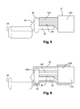
- a sealing sleeve 40 for example a heat-shrinkable polymer sleeve, is placed around the end of the core. 12A and the first end 22 of the member 20, as shown in particular on the figure 6 .
- a first end 40A of the sleeve is placed in sealed contact with the sheath 12G surrounding the core 12A of the first conductor and a second end 40B of this sleeve 40 is placed in sealing contact with a sealing bead 42 of the connecting member 20.
- bead 40 closes the second end 40B of the sleeve.
- the sleeve 40 may be replaced by a ribbon, a mass of overmolded material, a coating layer such as a varnish or equivalent means placed around the end of the core 12A the first conductor and the first end 22 of the connecting member.
- the end of the copper core 14A is connected.
- the second conductor at the second end 24 of the connecting member 20 by crimping the deformable end B of the lug 16 around the end of the core 14A of the second conductor juxtaposed to the second end 24 of the organ connection 20.
- the cores 12A and 14A of the conductors 12 and 14 are connected to the member 20 itself connected to the lug 16 as shown in FIGS. Figures 7 and 8 .
- the cores 12A, 14A of the two conductors are connected to the connecting member 20 so as not to touch one another, which in particular avoids favoring corrosion of electrochemical or galvanic origin, all the more so since the The end of the aluminum core 12A is protected by the sealing sleeve 40.
- the copper core 14A of the second conductor can be crimped onto the connection member 20 before the aluminum core 12A of the first conductor is welded to this connection member 20.
Landscapes
- Engineering & Computer Science (AREA)
- Manufacturing & Machinery (AREA)
- Connections Effected By Soldering, Adhesion, Or Permanent Deformation (AREA)
Applications Claiming Priority (1)
| Application Number | Priority Date | Filing Date | Title |
|---|---|---|---|
| FR1159082A FR2981214B1 (fr) | 2011-10-07 | 2011-10-07 | Raccordement de deux conducteurs electriques sur un element formant cosse electrique |
Publications (2)
| Publication Number | Publication Date |
|---|---|
| EP2579391A1 true EP2579391A1 (de) | 2013-04-10 |
| EP2579391B1 EP2579391B1 (de) | 2014-12-03 |
Family
ID=45992387
Family Applications (1)
| Application Number | Title | Priority Date | Filing Date |
|---|---|---|---|
| EP20120187597 Active EP2579391B1 (de) | 2011-10-07 | 2012-10-08 | Anschluss von zwei elektrischen Leitern an ein Element, das ein elektrisches Anschlussstück bildet |
Country Status (2)
| Country | Link |
|---|---|
| EP (1) | EP2579391B1 (de) |
| FR (2) | FR2981214B1 (de) |
Cited By (1)
| Publication number | Priority date | Publication date | Assignee | Title |
|---|---|---|---|---|
| CN112615168A (zh) * | 2020-12-07 | 2021-04-06 | 西安航天动力测控技术研究所 | 漆包线与导线紧凑连接器及方法 |
Citations (5)
| Publication number | Priority date | Publication date | Assignee | Title |
|---|---|---|---|---|
| DE102004050001A1 (de) * | 2004-10-14 | 2006-04-20 | Contitech Techno-Chemie Gmbh | Crimpverbindung |
| US20070119838A1 (en) * | 2003-05-12 | 2007-05-31 | Ola Pettersen | Novel connecting piece of electrically conducting material preferably a cable terminal and a mehtod of producing the same |
| EP1909361A1 (de) * | 2006-10-03 | 2008-04-09 | Valeo Electronique et Systèmes de Liaison | Montage von Stäben und Mehrleiterkabeln mit zwischengeschaltetem Bandplatte |
| US20080265004A1 (en) * | 2005-10-10 | 2008-10-30 | Schunk Ultraschalltechnik Gmbh | Method for Producing a Welded Joint Between Electrical Conductors by Means of an Ultrasonic Welding Method |
| US20090181579A1 (en) * | 2008-01-11 | 2009-07-16 | Robert Telakowski | Terminal with multiple wire connection |
Family Cites Families (3)
| Publication number | Priority date | Publication date | Assignee | Title |
|---|---|---|---|---|
| JP2002025647A (ja) * | 2000-07-03 | 2002-01-25 | Sumitomo Wiring Syst Ltd | 電線端末部の防水構造 |
| DE112006000768B4 (de) * | 2005-04-01 | 2013-08-08 | Autonetworks Technologies, Ltd. | Leiter- und Kabelbaum |
| JP4631951B2 (ja) * | 2008-09-19 | 2011-02-16 | パナソニック株式会社 | 巻線コイルと銅線との洗濯機用電気接続手段 |
-
2011
- 2011-10-07 FR FR1159082A patent/FR2981214B1/fr not_active Expired - Fee Related
-
2012
- 2012-01-05 FR FR1250128A patent/FR2981215B1/fr not_active Expired - Fee Related
- 2012-10-08 EP EP20120187597 patent/EP2579391B1/de active Active
Patent Citations (5)
| Publication number | Priority date | Publication date | Assignee | Title |
|---|---|---|---|---|
| US20070119838A1 (en) * | 2003-05-12 | 2007-05-31 | Ola Pettersen | Novel connecting piece of electrically conducting material preferably a cable terminal and a mehtod of producing the same |
| DE102004050001A1 (de) * | 2004-10-14 | 2006-04-20 | Contitech Techno-Chemie Gmbh | Crimpverbindung |
| US20080265004A1 (en) * | 2005-10-10 | 2008-10-30 | Schunk Ultraschalltechnik Gmbh | Method for Producing a Welded Joint Between Electrical Conductors by Means of an Ultrasonic Welding Method |
| EP1909361A1 (de) * | 2006-10-03 | 2008-04-09 | Valeo Electronique et Systèmes de Liaison | Montage von Stäben und Mehrleiterkabeln mit zwischengeschaltetem Bandplatte |
| US20090181579A1 (en) * | 2008-01-11 | 2009-07-16 | Robert Telakowski | Terminal with multiple wire connection |
Cited By (2)
| Publication number | Priority date | Publication date | Assignee | Title |
|---|---|---|---|---|
| CN112615168A (zh) * | 2020-12-07 | 2021-04-06 | 西安航天动力测控技术研究所 | 漆包线与导线紧凑连接器及方法 |
| CN112615168B (zh) * | 2020-12-07 | 2022-08-12 | 西安航天动力测控技术研究所 | 漆包线与导线紧凑连接器及方法 |
Also Published As
| Publication number | Publication date |
|---|---|
| FR2981215B1 (fr) | 2015-02-06 |
| FR2981214B1 (fr) | 2014-09-12 |
| FR2981214A1 (fr) | 2013-04-12 |
| EP2579391B1 (de) | 2014-12-03 |
| FR2981215A1 (fr) | 2013-04-12 |
Similar Documents
| Publication | Publication Date | Title |
|---|---|---|
| EP3496213B1 (de) | Impedanzanpassungsteil für steckverbinder, der auf einem kabel mit isolierten elektrischen drähten montiert ist | |
| EP2432078A2 (de) | Abgedichtete Quetschverbindungsverfahren | |
| WO2006106971A1 (ja) | 導電体及びワイヤーハーネス | |
| JP6373077B2 (ja) | 圧着端子付き電線 | |
| JP5076072B2 (ja) | 圧着端子、及びこの圧着端子を用いた圧着構造 | |
| WO2013032030A1 (en) | Electric cable end processing method and electric cable end structure with solder coating and sheath protection | |
| WO2009122093A2 (fr) | Procede de reprise du blindage electromagnetique individuel de cables electriques d'un toron sur un connecteur electrique | |
| FR2917244A1 (fr) | Cosse de connexion. | |
| EP2579391B1 (de) | Anschluss von zwei elektrischen Leitern an ein Element, das ein elektrisches Anschlussstück bildet | |
| WO2017029453A1 (fr) | Dispositif de connexion électrique amélioré | |
| EP3024092A1 (de) | Zusammenbau einer anordnung von elektrischen anschlüssen | |
| EP1463149B1 (de) | Verfahren zum Abdichten eines vieladrigen Verbindungskabels | |
| KR101282631B1 (ko) | 전선의 단자 접속방법 | |
| FR2946468A1 (fr) | Dispositif de liaison entre un connecteur electrique et un cable electrique coaxial blinde et connecteur electrique correspondant | |
| EP1383202A1 (de) | Verbindungsanordnung zwischen Kabel und Kontaktelement | |
| FR3022406A1 (fr) | Organe de raccordement electrique pour circuit electrique de vehicule | |
| EP3118932B1 (de) | Elektrisches anschlussorgan für elemente eines elektrischen kabels | |
| FR3055169A1 (fr) | Circuit electrique ameliore pour vehicule automobile | |
| JP6276820B2 (ja) | 被覆電線の接合方法 | |
| FR2921206A1 (fr) | Assemblage de conducteurs par manchon de jonction etanche a double embouti, et procede de realisation d'assemblage correspondant. | |
| FR3075488A1 (fr) | Procede de fabrication d'un element de raccordement electrique a section evolutive | |
| FR3117690A1 (fr) | assemblage d’un câble électrique avec un terminal de câble | |
| EP2581986A1 (de) | Anschlussvorrichtung eines Kabelschutzmantels | |
| EP3053223A2 (de) | Verfahren zur herstellung eines elektrischen kontakts und elektrischer kontakt | |
| FR2991822A1 (fr) | Manchon de connexion pour cable blinde |
Legal Events
| Date | Code | Title | Description |
|---|---|---|---|
| PUAI | Public reference made under article 153(3) epc to a published international application that has entered the european phase |
Free format text: ORIGINAL CODE: 0009012 |
|
| AK | Designated contracting states |
Kind code of ref document: A1 Designated state(s): AL AT BE BG CH CY CZ DE DK EE ES FI FR GB GR HR HU IE IS IT LI LT LU LV MC MK MT NL NO PL PT RO RS SE SI SK SM TR |
|
| AX | Request for extension of the european patent |
Extension state: BA ME |
|
| RIN1 | Information on inventor provided before grant (corrected) |
Inventor name: BAUDEL, BASTIEN Inventor name: CHRETIEN, LOUIS Inventor name: FERRIERES, LAURENT Inventor name: SEGONI, JACQUES Inventor name: PONROY, ARNAUD |
|
| 17P | Request for examination filed |
Effective date: 20131009 |
|
| RBV | Designated contracting states (corrected) |
Designated state(s): AL AT BE BG CH CY CZ DE DK EE ES FI FR GB GR HR HU IE IS IT LI LT LU LV MC MK MT NL NO PL PT RO RS SE SI SK SM TR |
|
| GRAP | Despatch of communication of intention to grant a patent |
Free format text: ORIGINAL CODE: EPIDOSNIGR1 |
|
| RIC1 | Information provided on ipc code assigned before grant |
Ipc: H01R 4/62 20060101AFI20140610BHEP Ipc: H01R 43/048 20060101ALI20140610BHEP Ipc: H01R 4/72 20060101ALI20140610BHEP Ipc: H01R 43/02 20060101ALI20140610BHEP |
|
| INTG | Intention to grant announced |
Effective date: 20140623 |
|
| GRAS | Grant fee paid |
Free format text: ORIGINAL CODE: EPIDOSNIGR3 |
|
| GRAA | (expected) grant |
Free format text: ORIGINAL CODE: 0009210 |
|
| RIN1 | Information on inventor provided before grant (corrected) |
Inventor name: FERRIERES, LAURENT Inventor name: PONROY, ARNAUD Inventor name: BAUDEL, BASTIEN Inventor name: SEGONI, JACQUES Inventor name: CHRETIEN, LOUIS |
|
| AK | Designated contracting states |
Kind code of ref document: B1 Designated state(s): AL AT BE BG CH CY CZ DE DK EE ES FI FR GB GR HR HU IE IS IT LI LT LU LV MC MK MT NL NO PL PT RO RS SE SI SK SM TR |
|
| REG | Reference to a national code |
Ref country code: GB Ref legal event code: FG4D Free format text: NOT ENGLISH |
|
| REG | Reference to a national code |
Ref country code: CH Ref legal event code: EP Ref country code: AT Ref legal event code: REF Ref document number: 699845 Country of ref document: AT Kind code of ref document: T Effective date: 20141215 |
|
| REG | Reference to a national code |
Ref country code: IE Ref legal event code: FG4D Free format text: LANGUAGE OF EP DOCUMENT: FRENCH |
|
| REG | Reference to a national code |
Ref country code: DE Ref legal event code: R096 Ref document number: 602012004086 Country of ref document: DE Effective date: 20150108 |
|
| REG | Reference to a national code |
Ref country code: NL Ref legal event code: VDEP Effective date: 20141203 |
|
| REG | Reference to a national code |
Ref country code: AT Ref legal event code: MK05 Ref document number: 699845 Country of ref document: AT Kind code of ref document: T Effective date: 20141203 |
|
| PG25 | Lapsed in a contracting state [announced via postgrant information from national office to epo] |
Ref country code: NO Free format text: LAPSE BECAUSE OF FAILURE TO SUBMIT A TRANSLATION OF THE DESCRIPTION OR TO PAY THE FEE WITHIN THE PRESCRIBED TIME-LIMIT Effective date: 20150303 Ref country code: NL Free format text: LAPSE BECAUSE OF FAILURE TO SUBMIT A TRANSLATION OF THE DESCRIPTION OR TO PAY THE FEE WITHIN THE PRESCRIBED TIME-LIMIT Effective date: 20141203 Ref country code: ES Free format text: LAPSE BECAUSE OF FAILURE TO SUBMIT A TRANSLATION OF THE DESCRIPTION OR TO PAY THE FEE WITHIN THE PRESCRIBED TIME-LIMIT Effective date: 20141203 Ref country code: FI Free format text: LAPSE BECAUSE OF FAILURE TO SUBMIT A TRANSLATION OF THE DESCRIPTION OR TO PAY THE FEE WITHIN THE PRESCRIBED TIME-LIMIT Effective date: 20141203 Ref country code: LT Free format text: LAPSE BECAUSE OF FAILURE TO SUBMIT A TRANSLATION OF THE DESCRIPTION OR TO PAY THE FEE WITHIN THE PRESCRIBED TIME-LIMIT Effective date: 20141203 |
|
| REG | Reference to a national code |
Ref country code: LT Ref legal event code: MG4D |
|
| PG25 | Lapsed in a contracting state [announced via postgrant information from national office to epo] |
Ref country code: AT Free format text: LAPSE BECAUSE OF FAILURE TO SUBMIT A TRANSLATION OF THE DESCRIPTION OR TO PAY THE FEE WITHIN THE PRESCRIBED TIME-LIMIT Effective date: 20141203 Ref country code: RS Free format text: LAPSE BECAUSE OF FAILURE TO SUBMIT A TRANSLATION OF THE DESCRIPTION OR TO PAY THE FEE WITHIN THE PRESCRIBED TIME-LIMIT Effective date: 20141203 Ref country code: SE Free format text: LAPSE BECAUSE OF FAILURE TO SUBMIT A TRANSLATION OF THE DESCRIPTION OR TO PAY THE FEE WITHIN THE PRESCRIBED TIME-LIMIT Effective date: 20141203 Ref country code: HR Free format text: LAPSE BECAUSE OF FAILURE TO SUBMIT A TRANSLATION OF THE DESCRIPTION OR TO PAY THE FEE WITHIN THE PRESCRIBED TIME-LIMIT Effective date: 20141203 Ref country code: LV Free format text: LAPSE BECAUSE OF FAILURE TO SUBMIT A TRANSLATION OF THE DESCRIPTION OR TO PAY THE FEE WITHIN THE PRESCRIBED TIME-LIMIT Effective date: 20141203 Ref country code: GR Free format text: LAPSE BECAUSE OF FAILURE TO SUBMIT A TRANSLATION OF THE DESCRIPTION OR TO PAY THE FEE WITHIN THE PRESCRIBED TIME-LIMIT Effective date: 20150304 Ref country code: CY Free format text: LAPSE BECAUSE OF FAILURE TO SUBMIT A TRANSLATION OF THE DESCRIPTION OR TO PAY THE FEE WITHIN THE PRESCRIBED TIME-LIMIT Effective date: 20141203 |
|
| PG25 | Lapsed in a contracting state [announced via postgrant information from national office to epo] |
Ref country code: SK Free format text: LAPSE BECAUSE OF FAILURE TO SUBMIT A TRANSLATION OF THE DESCRIPTION OR TO PAY THE FEE WITHIN THE PRESCRIBED TIME-LIMIT Effective date: 20141203 Ref country code: RO Free format text: LAPSE BECAUSE OF FAILURE TO SUBMIT A TRANSLATION OF THE DESCRIPTION OR TO PAY THE FEE WITHIN THE PRESCRIBED TIME-LIMIT Effective date: 20141203 Ref country code: EE Free format text: LAPSE BECAUSE OF FAILURE TO SUBMIT A TRANSLATION OF THE DESCRIPTION OR TO PAY THE FEE WITHIN THE PRESCRIBED TIME-LIMIT Effective date: 20141203 Ref country code: PT Free format text: LAPSE BECAUSE OF FAILURE TO SUBMIT A TRANSLATION OF THE DESCRIPTION OR TO PAY THE FEE WITHIN THE PRESCRIBED TIME-LIMIT Effective date: 20150403 Ref country code: CZ Free format text: LAPSE BECAUSE OF FAILURE TO SUBMIT A TRANSLATION OF THE DESCRIPTION OR TO PAY THE FEE WITHIN THE PRESCRIBED TIME-LIMIT Effective date: 20141203 |
|
| PG25 | Lapsed in a contracting state [announced via postgrant information from national office to epo] |
Ref country code: PL Free format text: LAPSE BECAUSE OF FAILURE TO SUBMIT A TRANSLATION OF THE DESCRIPTION OR TO PAY THE FEE WITHIN THE PRESCRIBED TIME-LIMIT Effective date: 20141203 Ref country code: IS Free format text: LAPSE BECAUSE OF FAILURE TO SUBMIT A TRANSLATION OF THE DESCRIPTION OR TO PAY THE FEE WITHIN THE PRESCRIBED TIME-LIMIT Effective date: 20150403 |
|
| REG | Reference to a national code |
Ref country code: DE Ref legal event code: R097 Ref document number: 602012004086 Country of ref document: DE |
|
| PLBE | No opposition filed within time limit |
Free format text: ORIGINAL CODE: 0009261 |
|
| STAA | Information on the status of an ep patent application or granted ep patent |
Free format text: STATUS: NO OPPOSITION FILED WITHIN TIME LIMIT |
|
| PG25 | Lapsed in a contracting state [announced via postgrant information from national office to epo] |
Ref country code: DK Free format text: LAPSE BECAUSE OF FAILURE TO SUBMIT A TRANSLATION OF THE DESCRIPTION OR TO PAY THE FEE WITHIN THE PRESCRIBED TIME-LIMIT Effective date: 20141203 |
|
| REG | Reference to a national code |
Ref country code: FR Ref legal event code: PLFP Year of fee payment: 4 |
|
| 26N | No opposition filed |
Effective date: 20150904 |
|
| PG25 | Lapsed in a contracting state [announced via postgrant information from national office to epo] |
Ref country code: IT Free format text: LAPSE BECAUSE OF FAILURE TO SUBMIT A TRANSLATION OF THE DESCRIPTION OR TO PAY THE FEE WITHIN THE PRESCRIBED TIME-LIMIT Effective date: 20141203 |
|
| PG25 | Lapsed in a contracting state [announced via postgrant information from national office to epo] |
Ref country code: SI Free format text: LAPSE BECAUSE OF FAILURE TO SUBMIT A TRANSLATION OF THE DESCRIPTION OR TO PAY THE FEE WITHIN THE PRESCRIBED TIME-LIMIT Effective date: 20141203 |
|
| PG25 | Lapsed in a contracting state [announced via postgrant information from national office to epo] |
Ref country code: LU Free format text: LAPSE BECAUSE OF FAILURE TO SUBMIT A TRANSLATION OF THE DESCRIPTION OR TO PAY THE FEE WITHIN THE PRESCRIBED TIME-LIMIT Effective date: 20151008 |
|
| REG | Reference to a national code |
Ref country code: CH Ref legal event code: PL |
|
| PG25 | Lapsed in a contracting state [announced via postgrant information from national office to epo] |
Ref country code: MC Free format text: LAPSE BECAUSE OF FAILURE TO SUBMIT A TRANSLATION OF THE DESCRIPTION OR TO PAY THE FEE WITHIN THE PRESCRIBED TIME-LIMIT Effective date: 20141203 |
|
| REG | Reference to a national code |
Ref country code: IE Ref legal event code: MM4A |
|
| PG25 | Lapsed in a contracting state [announced via postgrant information from national office to epo] |
Ref country code: LI Free format text: LAPSE BECAUSE OF NON-PAYMENT OF DUE FEES Effective date: 20151031 Ref country code: CH Free format text: LAPSE BECAUSE OF NON-PAYMENT OF DUE FEES Effective date: 20151031 |
|
| REG | Reference to a national code |
Ref country code: FR Ref legal event code: PLFP Year of fee payment: 5 |
|
| PG25 | Lapsed in a contracting state [announced via postgrant information from national office to epo] |
Ref country code: IE Free format text: LAPSE BECAUSE OF NON-PAYMENT OF DUE FEES Effective date: 20151008 |
|
| PG25 | Lapsed in a contracting state [announced via postgrant information from national office to epo] |
Ref country code: HU Free format text: LAPSE BECAUSE OF FAILURE TO SUBMIT A TRANSLATION OF THE DESCRIPTION OR TO PAY THE FEE WITHIN THE PRESCRIBED TIME-LIMIT; INVALID AB INITIO Effective date: 20121008 Ref country code: SM Free format text: LAPSE BECAUSE OF FAILURE TO SUBMIT A TRANSLATION OF THE DESCRIPTION OR TO PAY THE FEE WITHIN THE PRESCRIBED TIME-LIMIT Effective date: 20141203 Ref country code: BG Free format text: LAPSE BECAUSE OF FAILURE TO SUBMIT A TRANSLATION OF THE DESCRIPTION OR TO PAY THE FEE WITHIN THE PRESCRIBED TIME-LIMIT Effective date: 20141203 |
|
| PG25 | Lapsed in a contracting state [announced via postgrant information from national office to epo] |
Ref country code: BE Free format text: LAPSE BECAUSE OF NON-PAYMENT OF DUE FEES Effective date: 20151031 |
|
| PG25 | Lapsed in a contracting state [announced via postgrant information from national office to epo] |
Ref country code: MT Free format text: LAPSE BECAUSE OF FAILURE TO SUBMIT A TRANSLATION OF THE DESCRIPTION OR TO PAY THE FEE WITHIN THE PRESCRIBED TIME-LIMIT Effective date: 20141203 |
|
| REG | Reference to a national code |
Ref country code: FR Ref legal event code: PLFP Year of fee payment: 6 |
|
| PG25 | Lapsed in a contracting state [announced via postgrant information from national office to epo] |
Ref country code: TR Free format text: LAPSE BECAUSE OF FAILURE TO SUBMIT A TRANSLATION OF THE DESCRIPTION OR TO PAY THE FEE WITHIN THE PRESCRIBED TIME-LIMIT Effective date: 20141203 Ref country code: MK Free format text: LAPSE BECAUSE OF FAILURE TO SUBMIT A TRANSLATION OF THE DESCRIPTION OR TO PAY THE FEE WITHIN THE PRESCRIBED TIME-LIMIT Effective date: 20141203 |
|
| REG | Reference to a national code |
Ref country code: FR Ref legal event code: PLFP Year of fee payment: 7 |
|
| PG25 | Lapsed in a contracting state [announced via postgrant information from national office to epo] |
Ref country code: AL Free format text: LAPSE BECAUSE OF FAILURE TO SUBMIT A TRANSLATION OF THE DESCRIPTION OR TO PAY THE FEE WITHIN THE PRESCRIBED TIME-LIMIT Effective date: 20141203 |
|
| P01 | Opt-out of the competence of the unified patent court (upc) registered |
Effective date: 20230515 |
|
| PGFP | Annual fee paid to national office [announced via postgrant information from national office to epo] |
Ref country code: DE Payment date: 20251020 Year of fee payment: 14 |
|
| PGFP | Annual fee paid to national office [announced via postgrant information from national office to epo] |
Ref country code: GB Payment date: 20251024 Year of fee payment: 14 |
|
| PGFP | Annual fee paid to national office [announced via postgrant information from national office to epo] |
Ref country code: FR Payment date: 20251027 Year of fee payment: 14 |