EP2579449B1 - Appareil pour générer de l'énergie à partir d'un moteur à turbine - Google Patents
Appareil pour générer de l'énergie à partir d'un moteur à turbine Download PDFInfo
- Publication number
- EP2579449B1 EP2579449B1 EP12187272.5A EP12187272A EP2579449B1 EP 2579449 B1 EP2579449 B1 EP 2579449B1 EP 12187272 A EP12187272 A EP 12187272A EP 2579449 B1 EP2579449 B1 EP 2579449B1
- Authority
- EP
- European Patent Office
- Prior art keywords
- generator
- power
- atu
- spool
- integrated
- Prior art date
- Legal status (The legal status is an assumption and is not a legal conclusion. Google has not performed a legal analysis and makes no representation as to the accuracy of the status listed.)
- Active
Links
Images




Classifications
-
- B—PERFORMING OPERATIONS; TRANSPORTING
- B60—VEHICLES IN GENERAL
- B60R—VEHICLES, VEHICLE FITTINGS, OR VEHICLE PARTS, NOT OTHERWISE PROVIDED FOR
- B60R16/00—Electric or fluid circuits specially adapted for vehicles and not otherwise provided for; Arrangement of elements of electric or fluid circuits specially adapted for vehicles and not otherwise provided for
- B60R16/02—Electric or fluid circuits specially adapted for vehicles and not otherwise provided for; Arrangement of elements of electric or fluid circuits specially adapted for vehicles and not otherwise provided for electric constitutive elements
- B60R16/03—Electric or fluid circuits specially adapted for vehicles and not otherwise provided for; Arrangement of elements of electric or fluid circuits specially adapted for vehicles and not otherwise provided for electric constitutive elements for supply of electrical power to vehicle subsystems or for
-
- H—ELECTRICITY
- H02—GENERATION; CONVERSION OR DISTRIBUTION OF ELECTRIC POWER
- H02P—CONTROL OR REGULATION OF ELECTRIC MOTORS, ELECTRIC GENERATORS OR DYNAMO-ELECTRIC CONVERTERS; CONTROLLING TRANSFORMERS, REACTORS OR CHOKE COILS
- H02P9/00—Arrangements for controlling electric generators for the purpose of obtaining a desired output
-
- H—ELECTRICITY
- H02—GENERATION; CONVERSION OR DISTRIBUTION OF ELECTRIC POWER
- H02P—CONTROL OR REGULATION OF ELECTRIC MOTORS, ELECTRIC GENERATORS OR DYNAMO-ELECTRIC CONVERTERS; CONTROLLING TRANSFORMERS, REACTORS OR CHOKE COILS
- H02P25/00—Arrangements or methods for the control of AC motors characterised by the kind of AC motor or by structural details
- H02P25/16—Arrangements or methods for the control of AC motors characterised by the kind of AC motor or by structural details characterised by the circuit arrangement or by the kind of wiring
- H02P25/22—Multiple windings; Windings for more than three phases
Definitions
- Turbine engines and particularly gas turbine engines, also known as combustion turbine engines, are rotary engines that extract energy from a flow of combusted gases passing through the engine onto a multitude of turbine blades.
- Gas turbine engines have been used for land and nautical locomotion and power generation, but are most commonly used for aeronautical applications such as for airplanes, including helicopters. In airplanes, gas turbine engines are used for propulsion of the aircraft.
- Gas turbine engines can have two or more spools, including a low pressure (LP) spool that provides a significant fraction of the overall propulsion system thrust, and a high pressure (HP) spool that drives one or more compressors and produces additional thrust by directing exhaust products in an aft direction.
- LP low pressure
- HP high pressure
- a triple spool gas turbine engine includes a third, intermediate pressure (IP) spool.
- Gas turbine engines also usually power a number of different accessories such as generators, starter/generators, permanent magnet alternators (PMA), fuel pumps, and hydraulic pumps, e.g., equipment for functions needed on an aircraft other than propulsion.
- generators starter/generators, permanent magnet alternators (PMA)
- PMA permanent magnet alternators
- fuel pumps e.g., fuel pumps, and hydraulic pumps, e.g., equipment for functions needed on an aircraft other than propulsion.
- PMA permanent magnet alternators
- fuel pumps e.g., fuel pumps, and hydraulic pumps, e.g., equipment for functions needed on an aircraft other than propulsion.
- a generator coupled with a gas turbine engine will convert the mechanical power of the engine into electrical energy needed to power accessories, as described, e.g. in US 2010 /0314877 A1 , related to a counter rotating generator for gas turbine bleed energy recovery.
- Autotransformers are frequently used in power applications to interconnect systems operating at different voltage classes and to reduce the harmonic contents of the generators and the ripples at the outputs of the rectifiers.
- autotransformers typically are used to step up or down voltages between generators and rectifiers.
- ATUs are separate from the generator, and add to the weight and volume of the engine.
- an electrical architecture for a gas turbine engine having a high pressure (HP) spool and a low pressure (LP) spool includes a first AC generator coupled to the LP spool and comprising a first integrated auto transformer unit having at least two three-phase outputs from the first integrated auto transformer unit, a second AC generator coupled to the HP spool and comprising a second integrated auto transformer unit having at least two three-phase outputs from the second integrated auto transformer unit, a first AC/DC converter connected to the at least two three-phase outputs of the first AC generator, and to a first DC bus, and a second AC/DC converter connected to the at least two three-phase outputs of the second AC generator, and to a second DC bus, wherein the first and second DC buses are selectively connected, and wherein at least some electrical windings required for power transformation in the first and/or second integrated auto transformer unit are integrated with electrical winding of the first and/or second AC generator, respectively.
- the described embodiments of the present invention are directed to power extraction from an aircraft engine, and more particularly to an electrical power system architecture which enables production of electrical power from a turbine engine, preferably a gas turbine engine. It will be understood, however, that the invention is not so limited and has general application to electrical power system architectures in non-aircraft applications, such as other mobile applications and non-mobile industrial, commercial, and residential applications.
- FIG. 1 is a schematic cross-sectional diagram of a gas turbine engine 10 for an aircraft.
- Engine 10 includes, in downstream serial flow relationship, a fan section 12 including a fan 14, a booster or low pressure (LP) compressor 16, a high pressure (HP) compressor 18, a combustion section 20, a HP turbine 22, and a LP turbine 24.
- a HP shaft or spool 26 drivingly connects HP turbine 22 to HP compressor 18 and a LP shaft or spool 28 drivingly connects LP turbine 24 to LP compressor 16 and fan 14.
- HP turbine 22 includes an HP turbine rotor 30 having turbine blades 32 mounted at a periphery of rotor 30. Blades 32 extend radially outwardly from blade platforms 34 to radially outer blade tips 36.
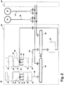
- FIG. 2 is a schematic block diagram of an electrical power system architecture 40 according to a first embodiment of the invention.
- the system architecture 40 includes multiple engine systems, shown herein as including at least a left engine system 42 and a right engine system 44.
- the left and right engine systems 42, 44 may be substantially identical; therefore, only the left engine system 42 will be described in detail for the sake of brevity.
- the left engine system 42 can include the HP and LP spools 26, 28 of the gas turbine engine 10 shown in FIG. 1 , although the system architecture 40 has application to other engines as well.
- the left engine system 42 shown herein uses mechanical power provided by two spools, the HP spool 26 and the LP spool 28.
- system architecture 40 could also be implemented on an engine having more than two spools, such as a 3-spool engine having an intermediate pressure spool in addition to the HP and LP spools.
- the system architecture 40 can further include an auxiliary power unit (APU) 46 of the aircraft and an external power source (EPS) 48.
- APU auxiliary power unit
- EPS external power source
- the APU 46 and EPS 48 each have a DC output 50, 52, respectively.
- the left engine system 42 includes a first autotransformer unit (ATU) integrated generator 56, shown herein as an ATU integrated starter-generator 56, configured to produce variable frequency (VF) AC power from mechanical power supplied by the HP spool 26, and a second ATU integrated generator 58 configured to produce constant frequency (CF) AC power from mechanical power supplied by the LP spool 28.
- ATU autotransformer unit
- the ATU integrated starter-generator 56 includes a power generation section 60 and an ATU section 62.
- the ATU section 62 is integrated with the power generation section 60 by integrating some of the electrical windings necessary for power transformation on the electrical winding of the power generation section 60. This essentially eliminates winding duplication in the power generation section 60 and the ATU section 62, which can translate into weight and cost savings for the aircraft.
- the HP spool 26 can be operably coupled with the ATU integrated starter-generator 56 by an HP drive assembly having an input mechanically coupled to the HP spool 26 and an output mechanically coupled to the power generation section 62.
- One embodiment of the HP drive assembly is an accessory gearbox 64, where the ATU integrated starter-generator 56 can be mounted and coupled to the accessory gearbox 64. Within the accessory gearbox 64, power may also be transferred to other engine accessories.
- the power generation section 60 of the ATU integrated starter-generator 56 converts mechanical power supplied by the HP spool 26 into electrical power and produces a power supply 66 having three phase outputs.
- the ATU section 62 of the ATU integrated starter-generator 56 functions to both transform the three phase outputs of the power supply 66 into a nine phase power output 68 and to step up the voltage of the power supply.
- the ATU integrated starter-generator 56 also provides a starting function to the aircraft.
- the ATU integrated generator 56 on the HP side of the left engine system 42 may comprise a generator that does not provide a starting function to the aircraft.
- a separate starter motor connected to the accessory gearbox 60 can be provided to perform the starting function for the aircraft.
- the left engine system 42 can include multiple generators drawing mechanical power from the HP spool 26 to produce power in order to provide a measure of redundancy.
- the ATU integrated generator 58 includes a power generation section 70 and an ATU section 72.
- the LP spool 28 can be operably coupled with the ATU integrated generator 58 by an LP drive assembly having an input mechanically coupled to the LP spool 28 and an output mechanically coupled to the power generation section 70.
- One embodiment of the LP drive assembly is a constant speed drive (CSD) 74 which converts the variable speed input from the LP spool 28 to constant speed.
- the CSD 74 can be mechanically coupled to the ATU integrated generator 58 and drives the power generation section 70 at a constant speed.
- the power generation section 70 of the ATU integrated generator 58 converts mechanical power supplied by the LP spool 28 into electrical power and produces a power supply 76 having three phase outputs.
- the ATU section 72 of the ATU integrated generator 58 functions to both transform the three phase outputs of the power supply 76 into a nine phase power output 78 and to step up the voltage of the power supply. Due to the CSD, the power supplies 66, 76 will have constant frequency. Alternatively, the CSD 74 can be eliminated to produce a VF power output.
- ATU integrated generator 58 may be used on the LP side of the left engine system 42
- another embodiment of the invention may use multiple ATU integrated generators 58 drawing mechanical power from the LP spool 28 to produce AC power in order to provide a measure of redundancy.
- ATU integrated generator 58 and CSD 74 are discussed herein, an integrated drive generator which combines the CSD 74 and ATU integrated generator 58 into a common unit can alternatively be used.
- the power output 68 from the an integrated ATU integrated starter-generator 56 is supplied to first AC/DC converter for converting the AC power output 68 to a DC power output 80.
- the first AC/DC converter can include a first rectifier device 82 and a first filter 84 for converting the AC voltage to DC voltage and for evening out the current flow before being supplied to a first electrical bus 86.
- the power output 78 from the ATU integrated generator 58 is supplied to second AC/DC converter for converting the AC power output 78 to a DC power output 88.
- the second AC/DC converter can include a second rectifier device 90 and a second filter 92 for converting the AC voltage to DC voltage and for evening out the current flow before being supplied to a second electrical bus 94.
- a motor-starter controller 96 can selectively provide power from the first electrical bus 86 to the ATU integrated starter-generator 56 to initiate a starting procedure for the aircraft.
- the motor-starter controller 96 can be integrated with the ATU integrated starter-generator 56 for engine starting by connecting the motor-starter controller 96 to the specific location of the ATU integrated starter-generator 56 as shown FIG. 2 .
- the three phase motor-starter controller 96 is connected to the three phase power supply 66 to drive the ATU integrated starter-generator 56 as a three phase starter for engine starting.
- the first and second electrical buses 86, 94 are configured to supply DC power to one or more loads (not shown) that require a DC power supply.
- the first and second electrical buses 86, 94 can be selectively connected to enable loads to be shared by the HP spool 26 and the LP spool 28.
- HPT 22 rotates the HP spool 26 and the LPT 24 rotates the LP spool.
- the accessory gearbox 64 is driven by the rotating HP spool 26, and transmits mechanical power from the HP spool 26 to the ATU integrated starter-generator 56.
- the ATU integrated starter-generator 56 converts mechanical power supplied by the HP spool 26 into electrical power and produces the DC power output 80.
- the CSD 74 is driven by the rotating LP spool 28, and transmits mechanical power from the LP spool 28 to the ATU integrated generator 58.
- the ATU integrated generator 58 converts the mechanical power supplied by the LP spool 28 into electrical power and produces the DC power output 88.
- the power outputs 80, 88 can be respectively provided to the electrical buses 86, 94 configured to supply DC power to one or more loads (not shown) that require a DC power supply. Depending on the type of load drawing power, the DC power extracted by the system architecture 40 may undergo further processing before being used by the loads.
- the DC power outputs 50, 52 of the APU 44 and the EPS 48 can also be provided to the electrical buses 86, 94.
- the left and right engine systems 42, 44, APU 46 and EPS 48 can provide DC power to various loads of the aircraft as needed.
- the various DC outputs of the left engine system 42, the right engine system 44, the APU 46, and the EPS 48 are integrated with appropriate switches to provide no break power transfer (NBPT) to the aircraft.
- NBPT no break power transfer
- FIG. 3 is an electrical diagram of the ATU integrated starter-generator 56 and the first AC-to-DC power converter for use in the electrical power system architecture 40 of Fig. 2 .
- the first and second ATU integrated generators 56, 58 and AC-to-DC power converters may be substantially identical for both the HP spool 26 and the LP spool 28; therefore, only the HP side of the left engine system 42 will be described in detail in FIG. 3 for the sake of brevity.
- the ATU integrated starter-generator 56 can have a stator with three main or primary windings 98a to 98c and nine secondary windings 100a to 100i.
- the main windings 98a to 98c each have a neutral end connected to a common neutral point 102 and a tap 104a to 104c connected to one phase output 106a to 106c of the three phase output power supply 66.
- the phase outputs 106a to 106c are provided via conductors or lead wires to the three-phase motor-starter controller 96 ( FIG. 2 ).
- the secondary windings 100a to 100i are connected in associated trios to one of the taps 104a to 104c on the main windings 98a to 98c, and are configured to generate the nine phase power output 68.
- the primary windings 98a to 98c are arranged in a Wye configuration, with the overall configuration of integrated ATU being a star connected configuration.
- the primary windings 98a to 98c can be arranged in a Delta configuration, with the overall configuration of integrated ATU being a Delta or Extended Delta connected configuration.
- the nine phase power output 68 is delivered by conductors 108a to 108i to the rectifier device 82.
- the conductors 108a to 108i can be lead wires.
- the rectifier device 82 can be integrated and packaged with the generator 56, or provided separately from the generator 56.
- the rectifier device 82 can include three rectifier bridges containing multiple diodes. The number of diodes is equal to the desired pulse count of the ATU integrated starter-generator 56. As shown herein, there are eighteen diodes, and so the pulse count is eighteen. Other numbers of diodes, such as 12, 18, 24, other multiples of six, etc. can also be used.
- One suitable type of diode is made from silicon carbide (SiC) due to its high temperature capability. Rectifying devices other than diodes can be used.
- the starter-generator 56 can be configured to have other pulse counts. For example, by providing two secondary windings 100 instead of three, a generator with a pulse count of twelve can be provided. In another example, by providing four secondary windings 100 instead of three, a generator with a pulse count of twenty-four can be provided.
- the conductors 108a, 108e, and 108i are connected to a first rectifier bridge 110 having six diodes 112
- the conductors 108c, 108d, and 108h are connected to a second rectifier bridge 114 having six diodes 116
- the conductors 108b, 108f, and 108g are connected to a third rectifier bridge 118 having six diodes 120.
- the three phases available on the conductors 108a, 108e, and 108i are rectified by the first rectifier bridge 110, with the diodes 112 delivering a first DC voltage between two first outputs 122a and 122b.
- the three phases available on the conductors 108c, 108d, and 108h are rectified in parallel by the second rectifier bridge 114, with the diodes 116 delivering a second DC voltage between two second outputs 124a and 124b.
- the three phases available on the conductors 108b, 108f, and 108g are also rectified in parallel by the third rectifier bridge 118, with the diodes 120 delivering a second DC voltage between two third outputs 126a and 126b.
- One output 122a, 124a, and 126a from each rectifier bridge 110, 114, 118 is coupled to a first interphase transformer 128 which absorbs the instantaneous voltage differences between the outputs 122a, 124a, and 126a.
- the other output 122b, 124b, and 126b from each rectifier bridge 110, 114, 118 is coupled to a second interphase transformer 130 which absorbs the instantaneous voltage differences between the outputs 122b, 124b, and 126b.
- the junction points between the coils of the first and second interphase transformers 128, 130 form first and second outputs 132, 134, respectively, which are connected to the filter 84.
- FIG. 4 is an electrical diagram of the stator winding for the ATU section 62 of the ATU integrated starter-generator 56 from FIG. 3 .
- each main winding 98a to 98c extends from the common neutral point 102 to one of the taps 104a to 104c.
- the secondary windings 100a to 100c on the first main winding 98a extend from the tap 104a to a terminal A1, A2, A3, respectively.
- the secondary windings 100d to 100f on the second main winding 98b extend from the tap 104b to a terminal B1, B2, B3, respectively.
- the secondary windings 100g to 100i on the third main winding 98c extend from the tap 104c to a terminal C1, C2, C3, respectively.
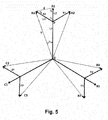
- FIG. 5 is a winding vector diagram for the stator winding for the ATU section 62 of the ATU integrated starter-generator 56 of FIG. 4 .
- the winding vector diagram can be used to design the stator winding for the ATU section 62 of the ATU integrated starter-generator 56.
- the stator winding is illustrated herein as having a pulse count of eighteen, although the stator winding can also be configured to have a pulse count in other multiple of six, such as 12, 18, 24, etc.
- the vector diagram includes nine main vectors A1, A2, A3, B1, B2, B3, C1, C2, C3 emanating from a common point of origin O, which corresponds to the neutral point 102 of the stator winding in FIG. 4 .
- the main vectors A1-C3 represent the phase outputs which are delivered by conductors 108a to 108i to the rectifier device 82 in FIG. 3 .
- the magnitude or length V of the main vectors A1-C3 represents the generated AC voltage and the direction or orientation of each main vector A1-C3 represents the phase from 0-360° of the generated AC voltage.
- the main vectors A1-C3 can have the same length V, but differ in phase by an angle ⁇ .
- the main vectors A1-C3 can be grouped, such that main vectors A1, B1, C1 represent the one three-phase output, the main vectors A2, B2, C2 represent another three-phase output, and the main vectors A3, B3, C3 represent the other three-phase output
- Each of the main vectors A1, B1, and C1 includes two sub-vectors X1, X2, Y1, Y2, Z1, Z2 emanating from a point P (which corresponds to the taps 104a-c in FIG. 4 ) to meet one of the other main vectors A2, A3, B2, B3, C2, C3.
- the distance between the common point of origin O and point P is represented as length L1.
- the distance from point P to the end of main vector A1 is represented as length L2.
- Sub-vector X2 extends from main vector A1 to main vector A3 at an angle ⁇ 1 and has a length L3. While not shown in FIG. 5 , the other sub-vectors X2, Y1, Y2, Z1, Z2 also have a length L3, and extend from the associated main vector at an angle equal to ⁇ 1.
- the ends of main vectors A1 and A3 are separated by a distance d, which together with lengths L2 and L3, form a triangle having vertices defining interior angles ⁇ 1, ⁇ 2, and ⁇ 3.
- the lengths L1-L3 and angles ⁇ 1 and ⁇ can be selected to design the stator winding for the ATU section 62 of the ATU integrated starter-generator 56 from FIG. 3 .
- the length L1 V ⁇ L 2
- the main stator winding for the ATU section 62 of the ATU integrated starter-generator 56 from FIG. 3 can be designed.
- the other variable given is ⁇ 1.
- another variable, such as a different angle or a length, could be given instead.
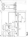
- FIG. 6 is a schematic block diagram of an electrical power system architecture 140 according to a second embodiment of the invention.
- the system architecture 140 may be substantially similar to the system architecture 40 shown in FIG. 2 ; therefore, like elements will be referred to using the same reference numerals.
- One difference between the system architecture 140 shown in FIG. 6 and the system architecture 40 shown in FIG. 2 is that, for both ATU integrated generators 56, 58, the ATU section 62, 72 functions to transform the three phase outputs of the power supply 66, 76 into a nine phase power output 142, 144 by adding two secondary windings instead of adding three windings.
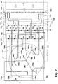
- FIG. 7 is an electrical diagram of the ATU integrated starter-generator 56 and the first AC-to-DC power converter for use in the electrical power system architecture 140 of Fig. 6 .
- the first and second ATU integrated generators 56, 58 and AC-to-DC power converters may be substantially identical for both the HP spool 26 and the LP spool 28; therefore, only the HP side of the left engine system 42 will be described in detail in FIG. 7 for the sake of brevity.
- the ATU integrated starter-generator 56 can have six secondary windings 146a to 146f connected in associated duos to one of the taps 104a to 104c on the main windings 98a to 98c.
- the primary windings 98a to 98c are arranged in a Wye configuration, with the overall configuration of integrated ATU being a fork connected configuration.
- the primary windings 98a to 98c can be arranged in a Delta configuration.
- the nine phase power output 142 is delivered by conductors 148a to 148i and 150a to 150c to the rectifier device 82.
- the conductors 148a, 148c, and 148e are connected to the second rectifier bridge 114 and the conductors 148b, 148d, 148f are connected to the third rectifier bridge 118.
- Conductors 150a to 150c extend from primary windings 98a to 98c, and are connected to the first rectifier bridge 110.
- the conductors 148a to 148i and 150a to 150c can be lead wires. The remaining rectification and filtering of the power is the same as described above for FIG. 3 .
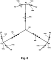
- FIG. 8 is an electrical diagram of the stator winding for the ATU section 62 of the ATU integrated starter-generator 56 from FIG. 7 . As discussed above, each main winding 98a to 98c extends from the common neutral point 102 to one of the taps 104a to 104c.
- the secondary windings 146a and 146b on the first main winding 98a extend from the tap 104a, also shown as terminal A1, to a terminal A2 and A3, respectively.
- the secondary windings 146c and 146d on the second main winding 98b extend from the tap 104b, as shown as terminal B1, to a terminal B2 and B3, respectively.
- the secondary windings 146e and 146f on the third main winding 98c extend from the tap 104c, also shown as terminal C1, to a terminal C2 and C3, respectively.
- FIG. 9 is a winding vector diagram for the stator winding for the ATU section 62 of the ATU integrated starter-generator 56 of FIG. 8 .
- the winding vector diagram can be used to design the stator winding for the ATU section 62 of the ATU integrated starter-generator 56.
- the stator winding is illustrated herein as having a pulse count of eighteen, although the stator winding can also be configured to have a pulse count in other multiple of six, such as 12, 18, 24, etc.
- the vector diagram includes nine main vectors A1, A2, A3, B1, B2, B3, C1, C2, C3 emanating from a common point of origin O, which corresponds to the neutral point 102 of the stator winding in FIG. 8 .
- the main vectors A1-C3 represent the phase outputs which are delivered by conductors 148a-f and 150a-c to the rectifier device 82 in FIG. 7 .
- the magnitude or length V of the main vectors A1-C3 represents the generated AC voltage and the direction or orientation of each main vector A1-C3 represents the phase from 0-360° of the generated AC voltage.
- the main vectors A1-C3 can have the same length V, but differ in phase by an angle ⁇ .
- Each of the main vectors A1, B1, and C1 includes two sub-vectors X1, X2, Y1, Y2, Z1, Z2 emanating from an end point E (which corresponds to the taps 104a-c in FIG. 8 ) to meet one of the other main vectors A2, A3, B2, B3, C2, C3.
- the distance between the common point of origin O and end point E is represented as length L1.
- Sub-vector X2 extends from main vector A1 to main vector A3 at an angle ⁇ and has a length L2. While not shown in FIG. 9 , the other sub-vectors X2, Y1, Y2, Z1, Z2 also have a length L2, and extend from the associated main vector at an angle equal to ⁇ .
- the lengths L1 and L2 and angles ⁇ and ⁇ can be selected to design the stator winding for the ATU section 62 of the ATU integrated starter-generator 56 from FIG. 7 .
- the main stator winding for the ATU section 62 of the ATU integrated starter-generator 56 from FIG. 3 can be designed.
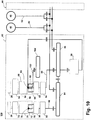
- FIG. 10 is a schematic block diagram of an electrical power system architecture 160 according to a third embodiment of the invention.
- the system architecture 160 may be substantially similar to the system architecture 40 shown in FIG. 2 ; therefore, like elements will be referred to using the same reference numerals.
- One difference between the system architecture 160 shown in FIG. 10 and the system architecture 40 shown in FIG. 2 is that the ATU section 62 includes an AC power output 162 that is supplied to an AC bus 164, in addition to the nine phase power output 68.
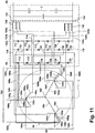
- FIG. 11 is an electrical diagram of the ATU integrated starter-generator 56 and the first AC-to-DC power converter for use in the electrical power system architecture 160 of Fig. 10 .
- the ATU integrated starter-generator 56 can be substantially similar to the ATU integrated starter-generator 56 of the first embodiment shown in FIG. 3 , with the exception that additional secondary windings 166a to 166c are provided on the main windings 98a to 98c.
- the additional secondary windings 166a to 166c can be connected by one of the taps 104a to 104c connected to one phase output 106a to 106c of the three phase output power supply 66.
- the phase outputs 106a to 106c are provided to the three-phase motor-starter controller 96 ( FIG.
- the AC power output 162 is delivered by conductors 168a to 168c from the windings 166a to 166c to the AC bus 164 ( FIG. 10 ) without being converted to DC by the rectifier device 82.
- the conductors 168a to 168c can be lead wires. The remaining rectification and filtering of the DC power is the same as described above for FIG. 3 .
- the system architecture disclosed herein provides an integrated ATU generator for an aircraft.
- One advantage that may be realized in the practice of some embodiments of the described systems and methods is that the traditional high pulse count ATU can be eliminated, and its equivalence is integrated into at least one of the generator (s) that is connected to a rectifying device to generate a low harmonic content DC output. This arrangement significantly reduces the weight of the engine, and can simplify the cooling for engine components.
- the provision of the integrated ATU generator can also eliminate the space needed for a separate ATU in the aircraft.
- ATU integrated starter-generator 56 does not jeopardize the use of the three phase motor-starter controller 96, since the motor-starter controller 96 is connected to the three phase power supply 66 before it is transformed to a nine phase power output in the ATU section 62 of the ATU integrated starter-generator 56.
- DC power can be extracted from both spools 26, 28 of a gas turbine engine 10.
- the operating efficiency of the gas turbine engine 10 is also increased by seamlessly controlling the power drawn from HP and LP spools 26, 28.
- the DC outputs 50, 52 from the APU 46 and the EPS 48 can be integrated to provide no break power transfer (NBPT).
- system architecture(s) can offer a level of redundant DC power generation, since DC power can be extracted from the LP spool 28 as well as the HP spool 26 of the gas turbine engine 10. Drawing power from both spools 26, 28 offers increased redundancy for DC power, such that in the event of a failure of one of the spools 26, 28 or generators 42, 44, DC power may still be extracted from the remaining operational spool 26, 28 and generator 42, 44.
- Still another advantage that may be realized in the practice of some embodiments of the described systems and methods is the avoidance of engine stall issues that are typically encountered during a descend mode of the aircraft by sharing the DC load between the HP and LP spools 26, 28. Being able to draw power from the LP spool as well as the HP spool permits allows the aircraft to run at lower rpms during descent without risk of stall, thereby preserving fuel efficiency of the aircraft.
Landscapes
- Engineering & Computer Science (AREA)
- Power Engineering (AREA)
- Mechanical Engineering (AREA)
- Control Of Eletrric Generators (AREA)
- Connection Of Motors, Electrical Generators, Mechanical Devices, And The Like (AREA)
Claims (3)
- Architecture électrique (40) destinée à un moteur à turbine (10) présentant un corps haute pression (HP) (26) et un corps basse pression (BP) (28) comprenant :un premier générateur CA (56) couplé au corps HP (26) et comprenant une première unité d'autotransformateur intégrée (62) présentant au moins deux sorties triphasées de la première unité d'autotransformateur intégrée ;un second générateur CA (58) couplé au corps BP (28) et comprenant une seconde unité d'autotransformateur intégrée (72) présentant au moins deux sorties triphasées de la seconde unité d'autotransformateur intégrée ;un premier convertisseur CA/CC (82, 84) connecté aux au moins deux sorties triphasées du premier générateur CA (56), et à un premier bus CC (86) ; etun second convertisseur CA/CC (90, 92) connecté aux au moins deux sorties triphasées du second générateur CA (58), et à un second bus CC (94) ;dans laquelle les premier et second bus CC (86, 94) sont connectés sélectivement ;et dans laquelle au moins certains enroulements électriques requis pour la transformation d'énergie dans la première et/ou la seconde unité d'autotransformateur intégrée (62, 72) sont intégrés à l'enroulement électrique du premier et/ou du second générateur CA (56, 58), respectivement.
- Architecture électrique (14) selon la revendication 1 et comprenant en outre un entraînement mécanique à vitesse constante (74) présentant une entrée accouplée mécaniquement au corps BP (28) et une sortie accouplée mécaniquement au second générateur CA (58).
- Architecture électrique (40) selon la revendication 2, dans laquelle le premier convertisseur CA/CC comprend en outre un premier filtre (84) connecté à une première matrice de redresseur (82) et configuré pour fournir une sortie CC au premier bus (86), et le second convertisseur CA/CC comprend en outre un second filtre (92) connecté à une seconde matrice de redresseur (90) et configuré pour fournir une sortie CC au second bus (94).
Applications Claiming Priority (1)
| Application Number | Priority Date | Filing Date | Title |
|---|---|---|---|
| US13/268,390 US8723349B2 (en) | 2011-10-07 | 2011-10-07 | Apparatus for generating power from a turbine engine |
Publications (3)
| Publication Number | Publication Date |
|---|---|
| EP2579449A2 EP2579449A2 (fr) | 2013-04-10 |
| EP2579449A3 EP2579449A3 (fr) | 2017-07-12 |
| EP2579449B1 true EP2579449B1 (fr) | 2020-09-23 |
Family
ID=46970143
Family Applications (1)
| Application Number | Title | Priority Date | Filing Date |
|---|---|---|---|
| EP12187272.5A Active EP2579449B1 (fr) | 2011-10-07 | 2012-10-04 | Appareil pour générer de l'énergie à partir d'un moteur à turbine |
Country Status (6)
| Country | Link |
|---|---|
| US (2) | US8723349B2 (fr) |
| EP (1) | EP2579449B1 (fr) |
| JP (1) | JP2013085457A (fr) |
| CN (1) | CN103036362B (fr) |
| BR (1) | BR102012025274A2 (fr) |
| CA (1) | CA2790958A1 (fr) |
Families Citing this family (41)
| Publication number | Priority date | Publication date | Assignee | Title |
|---|---|---|---|---|
| US8723349B2 (en) * | 2011-10-07 | 2014-05-13 | General Electric Company | Apparatus for generating power from a turbine engine |
| EP3004564A4 (fr) * | 2013-06-07 | 2016-11-23 | Ge Aviat Systems Llc | Réacteur à double flux équipé d'un générateur |
| GB2520024B (en) * | 2013-11-06 | 2016-02-03 | Ge Aviat Systems Ltd | Electrical power system for an aircraft |
| EP2886387A3 (fr) | 2013-12-23 | 2015-12-23 | Rolls-Royce Corporation | Moteur/générateur à double redondance pour un moteur |
| US20160348589A1 (en) * | 2014-11-24 | 2016-12-01 | Hamilton Sundstrand Corporation | Aircraft engine assembly and method of generating electric energy for an aircraft power system |
| US10000293B2 (en) | 2015-01-23 | 2018-06-19 | General Electric Company | Gas-electric propulsion system for an aircraft |
| US9764848B1 (en) | 2016-03-07 | 2017-09-19 | General Electric Company | Propulsion system for an aircraft |
| US10392119B2 (en) | 2016-04-11 | 2019-08-27 | General Electric Company | Electric propulsion engine for an aircraft |
| US10392120B2 (en) | 2016-04-19 | 2019-08-27 | General Electric Company | Propulsion engine for an aircraft |
| US10252810B2 (en) | 2016-04-19 | 2019-04-09 | General Electric Company | Propulsion engine for an aircraft |
| US11105340B2 (en) | 2016-08-19 | 2021-08-31 | General Electric Company | Thermal management system for an electric propulsion engine |
| US10800539B2 (en) * | 2016-08-19 | 2020-10-13 | General Electric Company | Propulsion engine for an aircraft |
| US10676205B2 (en) | 2016-08-19 | 2020-06-09 | General Electric Company | Propulsion engine for an aircraft |
| US10071811B2 (en) | 2016-08-22 | 2018-09-11 | General Electric Company | Embedded electric machine |
| US10093428B2 (en) | 2016-08-22 | 2018-10-09 | General Electric Company | Electric propulsion system |
| US10487839B2 (en) | 2016-08-22 | 2019-11-26 | General Electric Company | Embedded electric machine |
| US10308366B2 (en) | 2016-08-22 | 2019-06-04 | General Electric Company | Embedded electric machine |
| US10590853B2 (en) * | 2017-01-19 | 2020-03-17 | United Technologies Corporation | Gas turbine engine dual towershaft accessory gearbox assembly with a transmission |
| US10793281B2 (en) | 2017-02-10 | 2020-10-06 | General Electric Company | Propulsion system for an aircraft |
| US10822103B2 (en) | 2017-02-10 | 2020-11-03 | General Electric Company | Propulsor assembly for an aircraft |
| US11149578B2 (en) | 2017-02-10 | 2021-10-19 | General Electric Company | Propulsion system for an aircraft |
| US10137981B2 (en) | 2017-03-31 | 2018-11-27 | General Electric Company | Electric propulsion system for an aircraft |
| US10762726B2 (en) | 2017-06-13 | 2020-09-01 | General Electric Company | Hybrid-electric propulsion system for an aircraft |
| US10689999B2 (en) | 2018-02-22 | 2020-06-23 | Ge Aviation Systems, Llc | Power generation system |
| US11156128B2 (en) | 2018-08-22 | 2021-10-26 | General Electric Company | Embedded electric machine |
| US11097849B2 (en) | 2018-09-10 | 2021-08-24 | General Electric Company | Aircraft having an aft engine |
| US20200180771A1 (en) | 2018-12-06 | 2020-06-11 | General Electric Company | Thermal Management System for an Aircraft Including an Electric Propulsion Engine |
| JP7206143B2 (ja) | 2019-03-28 | 2023-01-17 | 三菱重工業株式会社 | 1軸式ガスタービンの運転制御装置、運転制御方法及びプログラム |
| US10868483B1 (en) * | 2019-06-03 | 2020-12-15 | Hamilton Sundstrand Corporation | DC generator system |
| US10950382B1 (en) * | 2020-01-10 | 2021-03-16 | The Boeing Company | Autotransformer rectifier unit with multiple alternating current level outputs |
| US11565824B2 (en) | 2020-04-08 | 2023-01-31 | General Electric Company | Electric generator |
| US11325714B2 (en) | 2020-07-09 | 2022-05-10 | General Electric Company | Electric power system for a vehicle |
| US11845388B2 (en) | 2021-05-20 | 2023-12-19 | General Electric Company | AC electrical power system for a vehicle |
| US12149154B2 (en) | 2021-07-22 | 2024-11-19 | General Electric Company | Electric machine having a hybrid insulative-conductive manifold |
| US11750114B2 (en) | 2021-10-22 | 2023-09-05 | General Electric Company | Reduction of common mode emission of an electrical power converter |
| GB2620554A (en) | 2022-07-04 | 2024-01-17 | Rolls Royce Plc | Electrical power system |
| EP4414541A1 (fr) * | 2023-02-07 | 2024-08-14 | The Boeing Company | Système hybride d'alimentation électrique à turbine et à arbres multiples pour aéronef |
| US12034306B1 (en) | 2023-02-07 | 2024-07-09 | The Boeing Company | Hybrid turbine and multiple-spool electric power system for aircraft |
| US12246843B2 (en) | 2023-02-07 | 2025-03-11 | The Boeing Company | Hybrid turbine and multiple-spool electric power system for aircraft |
| US12388322B2 (en) | 2023-03-24 | 2025-08-12 | Rolls-Royce North American Technologies, Inc. | Electric generator behind fan in turbine engine |
| US12525829B2 (en) | 2023-09-19 | 2026-01-13 | Rolls-Royce Corporation | Composite stator sleeve for electric machine |
Family Cites Families (95)
| Publication number | Priority date | Publication date | Assignee | Title |
|---|---|---|---|---|
| DE2531644C3 (de) * | 1974-07-22 | 1978-05-24 | Otdel Energetitscheskoj Kibernetiki Akademii Nauk Moldavskoj Ssr, Kischinew (Sowjetunion) | Phasenschiebereinrichtung für Spannungen eines elektrischen Netzes |
| US4956598A (en) * | 1988-12-16 | 1990-09-11 | Sundstrand Corporation | Low distortion control for a VSCF generating system |
| US5739676A (en) * | 1996-11-04 | 1998-04-14 | Ford Motor Company | Multiple-alternator electrical system |
| JP3211751B2 (ja) | 1997-03-24 | 2001-09-25 | トヨタ自動車株式会社 | 動力出力装置およびその制御方法 |
| KR20010108020A (ko) | 1998-12-14 | 2001-12-07 | 리차드 게쯜러 | 저 항력 덕트형 램 에어 터빈 발전기 및 냉각 장치 |
| US6281664B1 (en) * | 1999-01-13 | 2001-08-28 | Honda Giken Kogyo Kabushiki Kaisha | Generator and generator apparatus |
| US6615586B1 (en) | 1999-07-07 | 2003-09-09 | Mirela Shipley | High-pressure gas-turbine plant using high-pressure piston-type compressor |
| US6101113A (en) * | 1999-12-02 | 2000-08-08 | Paice; Derek A | Transformers for multipulse AC/DC converters |
| US6333622B1 (en) * | 2000-05-16 | 2001-12-25 | General Electric Company | Synchronous generator having auxiliary power windings and variable frequency power source |
| US6498736B1 (en) * | 2001-03-27 | 2002-12-24 | Baldor Electric Company | Harmonic filter with low cost magnetics |
| US6729139B2 (en) | 2001-09-26 | 2004-05-04 | Goodrich Pump & Engine Control Systems, Inc. | Engine control system |
| US6735951B2 (en) * | 2002-01-04 | 2004-05-18 | Hamilton Sundstrand Corporation | Turbocharged auxiliary power unit with controlled high speed spool |
| US7574867B2 (en) | 2003-04-02 | 2009-08-18 | Tma Power, Llc | Hybrid microturbine for generating electricity |
| US6950322B2 (en) * | 2003-04-10 | 2005-09-27 | Rsm Electron Power, Inc. | Regulated AC to DC converter for aerospace applications |
| US7367193B1 (en) | 2003-07-23 | 2008-05-06 | Hamilton Sundstrand Corporation | Auxiliary power unit control method and system |
| FR2859835B1 (fr) | 2003-09-11 | 2006-05-26 | Airbus France | Systeme de generation electrique a frequence fixe et procede de controle de celui-ci |
| US6931856B2 (en) | 2003-09-12 | 2005-08-23 | Mes International, Inc. | Multi-spool turbogenerator system and control method |
| DE10355917A1 (de) | 2003-11-29 | 2005-06-30 | Mtu Aero Engines Gmbh | Gasturbine, insbesondere Flugtriebwerk, und Verfahren zur Erzeugung elektrischer Energie bei einer Gasturbine |
| FR2863312B1 (fr) | 2003-12-09 | 2008-07-04 | Snecma Moteurs | Turboreacteur a double corps avec moyen d'entrainement des machines accessoires |
| US7188475B2 (en) | 2003-12-18 | 2007-03-13 | Honeywell International, Inc. | Starting and controlling speed of a two spool gas turbine engine |
| GB0415376D0 (en) | 2004-07-09 | 2004-08-11 | Rolls Royce Plc | A turbine engine arrangement |
| US7246482B2 (en) | 2004-07-16 | 2007-07-24 | Honeywell International, Inc. | Gas turbine engine bleed air power assist system and method |
| US7578136B2 (en) | 2004-08-23 | 2009-08-25 | Honeywell International Inc. | Integrated power and pressurization system |
| US20060174629A1 (en) | 2004-08-24 | 2006-08-10 | Honeywell International, Inc | Method and system for coordinating engine operation with electrical power extraction in a more electric vehicle |
| FR2875971B1 (fr) | 2004-09-24 | 2006-11-10 | Thales Sa | Convertisseur alternatif-continu pour l'aeronautique |
| FR2878286B1 (fr) | 2004-11-25 | 2009-05-22 | Snecma Moteurs Sa | Turbomachine comportant un generateur de courant electrique integre |
| FR2878287B1 (fr) | 2004-11-25 | 2009-05-22 | Snecma Moteurs Sa | Turboreacteur double corps double flux avec generateur de courant electrique arriere |
| FR2880920B1 (fr) | 2005-01-20 | 2007-07-06 | Snecma Moteurs Sa | Turbomoteur a double corps avec des moyens d'entrainement du boitier d'accessoires |
| FR2881896B1 (fr) | 2005-02-04 | 2011-06-10 | Airbus France | Systeme de generation electrique a frequence fixe a coupleur a induction et utilisation de celui-ci dans un aeronef |
| FR2882096B1 (fr) | 2005-02-11 | 2012-04-20 | Snecma Moteurs | Turbomoteur a double corps avec des moyens de prise de mouvement sur les rotors basse pression et haute pression, module de prise de mouvement pour le turbomoteur et procede de montage du turbomoteur |
| US20060225432A1 (en) | 2005-03-29 | 2006-10-12 | Awdalla Essam T | Supercharged open cycle gas turbine engine |
| US7513120B2 (en) | 2005-04-08 | 2009-04-07 | United Technologies Corporation | Electrically coupled supercharger for a gas turbine engine |
| US7552582B2 (en) | 2005-06-07 | 2009-06-30 | Honeywell International Inc. | More electric aircraft power transfer systems and methods |
| US20070022735A1 (en) | 2005-07-29 | 2007-02-01 | General Electric Company | Pto assembly for a gas turbine engine |
| FR2892456B1 (fr) | 2005-10-21 | 2008-01-04 | Hispano Suiza Sa | Dispositif d'entrainement de machines accessoires d'un moteur a turbine a gaz |
| FR2897485B1 (fr) | 2006-02-10 | 2008-06-06 | Artus Soc Par Actions Simplifi | Convertisseur ac/dc a autotransformateur |
| US20070240426A1 (en) | 2006-04-12 | 2007-10-18 | General Electric Company | Mehtod and controller for operating a gas turbine engine |
| US20070265761A1 (en) | 2006-05-11 | 2007-11-15 | Dooley Kevin A | Electric power generation system and method |
| US7621117B2 (en) | 2006-06-19 | 2009-11-24 | Pratt & Whitney Canada Corp. | Apparatus and method for controlling engine windmilling |
| JP4551916B2 (ja) | 2006-07-12 | 2010-09-29 | 川崎重工業株式会社 | トラクション変速機構付き発電・スタータ装置 |
| US7495353B2 (en) | 2006-08-01 | 2009-02-24 | Hamilton Sundstrand Corporation | Power interconnect block for an aircraft electrical component |
| GB2440747A (en) | 2006-08-10 | 2008-02-13 | Rolls Royce Plc | Hydrodynamic coupling with movable turbine for engine power take off |
| DE102006039608A1 (de) | 2006-08-24 | 2008-04-10 | Rolls-Royce Deutschland Ltd & Co Kg | Anordnung zur Energieentnahme bei einem Zwei-Wellen-Triebwerk |
| WO2008045068A1 (fr) | 2006-10-12 | 2008-04-17 | United Technologies Corporation | Turboréacteur à double flux à tuyère de soufflante à géométrie variable et générateur de corps inférieur permettant une alimentation d'urgence et procédé d'alimentation d'urgence |
| GB2443194B (en) * | 2006-10-24 | 2008-09-10 | Rolls-Royce Plc | Gas turbine engine |
| US7870742B2 (en) | 2006-11-10 | 2011-01-18 | General Electric Company | Interstage cooled turbine engine |
| US7788898B2 (en) | 2006-12-06 | 2010-09-07 | General Electric Company | Variable coupling of turbofan engine spools via open differential gear set or simple planetary gear set for improved power extraction and engine operability, with torque coupling for added flexibility |
| US7622817B2 (en) | 2006-12-13 | 2009-11-24 | General Electric Company | High-speed high-pole count generators |
| US7514810B2 (en) | 2006-12-15 | 2009-04-07 | General Electric Company | Electric power generation using power turbine aft of LPT |
| US7405542B1 (en) | 2006-12-20 | 2008-07-29 | The Boeing Company | Generator synchronization method on a common drive source and apparatus therefor |
| US8198744B2 (en) | 2006-12-21 | 2012-06-12 | General Electric Company | Integrated boost cavity ring generator for turbofan and turboshaft engines |
| US20080148881A1 (en) | 2006-12-21 | 2008-06-26 | Thomas Ory Moniz | Power take-off system and gas turbine engine assembly including same |
| US7791235B2 (en) | 2006-12-22 | 2010-09-07 | General Electric Company | Variable magnetic coupling of rotating machinery |
| US8319481B2 (en) * | 2006-12-26 | 2012-11-27 | Hamilton Sundstrand Corporation | Pole shifting generator |
| WO2008082336A1 (fr) | 2006-12-29 | 2008-07-10 | Volvo Aero Corporation | Dispositif de transmission de puissance pour une turbine à gaz, aéroplane et procédé de fonctionnement d'une turbine à gaz |
| WO2008082335A1 (fr) | 2006-12-29 | 2008-07-10 | Volvo Aero Corporation | Dispositif de transmission de puissance pour une turbine à gaz |
| US20100251726A1 (en) | 2007-01-17 | 2010-10-07 | United Technologies Corporation | Turbine engine transient power extraction system and method |
| US7942079B2 (en) | 2007-02-16 | 2011-05-17 | Hamilton Sundstrand Corporation | Multi-speed gearbox for low spool driven auxiliary component |
| US7468561B2 (en) | 2007-03-27 | 2008-12-23 | General Electric Company | Integrated electrical power extraction for aircraft engines |
| US8015828B2 (en) | 2007-04-03 | 2011-09-13 | General Electric Company | Power take-off system and gas turbine engine assembly including same |
| US7485981B2 (en) | 2007-05-09 | 2009-02-03 | United Technologies Corporation | Aircraft combination engines complemental connection and operation |
| US7882691B2 (en) | 2007-07-05 | 2011-02-08 | Hamilton Sundstrand Corporation | High to low pressure spool summing gearbox for accessory power extraction and electric start |
| FR2919896B1 (fr) | 2007-08-07 | 2009-10-30 | Snecma Sa | Turboreacteur comprenant un generateur de courant monte dans la soufflante et un procede de montage dudit generateur dans la soufflante |
| US7969122B2 (en) * | 2007-11-14 | 2011-06-28 | Hamilton Sundstrand Corporation | Pole count changing generator |
| US20090146425A1 (en) | 2007-12-11 | 2009-06-11 | Paul Widisky | System and apparatus for the generation of electical power |
| US7728477B2 (en) | 2008-01-17 | 2010-06-01 | Honeywell International Inc. | Dual purpose permanent magnet exciter |
| FR2930084B1 (fr) * | 2008-04-09 | 2012-06-08 | Thales Sa | Procede de gestion d'un reseau electrique |
| US8330411B2 (en) | 2008-04-14 | 2012-12-11 | Lockheed Martin Corporation | Electric vehicle battery charging by driving the propulsion shaft |
| US8181442B2 (en) | 2008-05-05 | 2012-05-22 | Pratt & Whitney Canada Corp. | Gas turbine aircraft engine with power variability |
| US7582981B1 (en) | 2008-05-19 | 2009-09-01 | Moshe Meller | Airborne wind turbine electricity generating system |
| US8146370B2 (en) | 2008-05-21 | 2012-04-03 | Honeywell International Inc. | Turbine drive system with lock-up clutch and method |
| DE102008031185A1 (de) | 2008-07-03 | 2010-01-07 | Rolls-Royce Deutschland Ltd & Co Kg | Turbofantriebwerk mit mindestens einer Vorrichtung zum Antreiben mindestens eines Generators |
| GB2462245B (en) | 2008-07-28 | 2010-09-22 | Rolls Royce Plc | Gas turbine engine arrangement |
| US8427001B2 (en) | 2008-07-30 | 2013-04-23 | Honeywell International, Inc. | Electrically controlled frequency-based power system architecture for aircraft |
| DE102008048915B4 (de) | 2008-09-26 | 2017-05-18 | Airbus Operations Gmbh | Leistungsverteilungssystem |
| US9121351B2 (en) | 2008-10-30 | 2015-09-01 | Rolls-Royce North American Technologies, Inc. | Gas turbine engine accessory system |
| GB0821684D0 (en) | 2008-11-28 | 2008-12-31 | Rolls Royce Plc | Aeroengine starter/generator arrangement |
| US8039983B2 (en) | 2008-12-02 | 2011-10-18 | The Boeing Company | Systems and methods for providing AC power from multiple turbine engine spools |
| US8237416B2 (en) | 2008-12-09 | 2012-08-07 | Hamilton Sundstrand Corporation | More electric engine with regulated permanent magnet machines |
| US20100154380A1 (en) | 2008-12-22 | 2010-06-24 | General Electric Company | Control system for a land-based simple cycle hybrid engine for power generation |
| US20100170262A1 (en) | 2009-01-06 | 2010-07-08 | Kaslusky Scott F | Aircraft power and thermal management system with electric co-generation |
| US8299732B2 (en) * | 2009-01-15 | 2012-10-30 | Rockwell Automation Technologies, Inc. | Power conversion system and method |
| JP4700113B2 (ja) | 2009-02-06 | 2011-06-15 | 川崎重工業株式会社 | 航空機用発電装置 |
| US8661781B2 (en) | 2009-02-13 | 2014-03-04 | The Boeing Company | Counter rotating fan design and variable blade row spacing optimization for low environmental impact |
| US8164208B2 (en) * | 2009-04-15 | 2012-04-24 | General Electric Company | Systems involving multi-spool generators and variable speed electrical generators |
| US8148834B2 (en) | 2009-05-19 | 2012-04-03 | General Electric Company | Aircraft engine starting/generating system and method of control |
| US8063501B2 (en) | 2009-06-10 | 2011-11-22 | Hamilton Sundstrand Corporation | Gas turbine bleed energy recovery via counter rotating generator |
| US8745990B2 (en) | 2009-07-27 | 2014-06-10 | Rolls-Royce Corporation | Gas turbine engine with integrated electric starter/generator |
| JP5016706B2 (ja) | 2009-11-04 | 2012-09-05 | 川崎重工業株式会社 | 航空機用始動発電装置 |
| US8684304B2 (en) * | 2010-11-16 | 2014-04-01 | Rolls-Royce Corporation | Aircraft, propulsion system, and system for taxiing an aircraft |
| US8561413B2 (en) * | 2010-12-29 | 2013-10-22 | Ge Aviation Systems, Llc | System for powering a vehicle |
| CN102142692A (zh) * | 2011-02-25 | 2011-08-03 | 南京航空航天大学 | 一种适用于变速风力发电的全功率变流器 |
| US8723385B2 (en) * | 2011-10-07 | 2014-05-13 | General Electric Company | Generator |
| US8723349B2 (en) * | 2011-10-07 | 2014-05-13 | General Electric Company | Apparatus for generating power from a turbine engine |
| US20130232941A1 (en) * | 2012-03-07 | 2013-09-12 | Ge Aviation Systems Llc | Apparatus for extracting input power from the low pressure spool of a turbine engine |
-
2011
- 2011-10-07 US US13/268,390 patent/US8723349B2/en active Active
-
2012
- 2012-09-27 CN CN201210368793.3A patent/CN103036362B/zh active Active
- 2012-09-27 CA CA2790958A patent/CA2790958A1/fr not_active Abandoned
- 2012-10-03 BR BR102012025274A patent/BR102012025274A2/pt not_active Application Discontinuation
- 2012-10-03 JP JP2012220936A patent/JP2013085457A/ja active Pending
- 2012-10-04 EP EP12187272.5A patent/EP2579449B1/fr active Active
-
2013
- 2013-02-19 US US13/769,970 patent/US8492920B2/en active Active
Non-Patent Citations (1)
| Title |
|---|
| None * |
Also Published As
| Publication number | Publication date |
|---|---|
| US20130088019A1 (en) | 2013-04-11 |
| US8723349B2 (en) | 2014-05-13 |
| EP2579449A3 (fr) | 2017-07-12 |
| CA2790958A1 (fr) | 2013-04-07 |
| CN103036362A (zh) | 2013-04-10 |
| EP2579449A2 (fr) | 2013-04-10 |
| JP2013085457A (ja) | 2013-05-09 |
| BR102012025274A2 (pt) | 2016-03-01 |
| US20130154359A1 (en) | 2013-06-20 |
| CN103036362B (zh) | 2018-03-27 |
| US8492920B2 (en) | 2013-07-23 |
Similar Documents
| Publication | Publication Date | Title |
|---|---|---|
| EP2579449B1 (fr) | Appareil pour générer de l'énergie à partir d'un moteur à turbine | |
| EP2579430B1 (fr) | Générateur électrique | |
| US9963095B2 (en) | Electrical power system for an aircraft | |
| US9257838B2 (en) | Circuit and method for allocating power among generators | |
| RU2464689C2 (ru) | Система генерирования, преобразования, распределения электроэнергии и запуска на борту самолета | |
| EP2568122A2 (fr) | Procédé et appareil permettant d'extraire de l'énergie électrique d'un moteur de turbine à gaz | |
| Avery et al. | Electrical generation and distribution for the more electric aircraft | |
| EP2636873A2 (fr) | Appareil pour extraire de la puissance de l'arbre basse pression d'un moteur à turbine | |
| US20170107910A1 (en) | Method and apparatus for starting an aircraft engine and operating a power architecture for an aircraft | |
| EP1047873A1 (fr) | Systeme de generation/demarrage tolerant aux anomalies | |
| US9680344B2 (en) | Multiphase electrical machine and method of use | |
| EP3621170A1 (fr) | Système d'alimentation hvdc | |
| CN111490688B (zh) | 电压转换器 | |
| RU2645866C2 (ru) | Электромеханическая система приведения в действие и/или генерирования, содержащая электрическую изоляцию между источником электрического напряжения и нагрузкой | |
| Freitas et al. | Design of DC-link VSCF AC electrical power system for the Embraer 190/195 aircraft |
Legal Events
| Date | Code | Title | Description |
|---|---|---|---|
| PUAI | Public reference made under article 153(3) epc to a published international application that has entered the european phase |
Free format text: ORIGINAL CODE: 0009012 |
|
| AK | Designated contracting states |
Kind code of ref document: A2 Designated state(s): AL AT BE BG CH CY CZ DE DK EE ES FI FR GB GR HR HU IE IS IT LI LT LU LV MC MK MT NL NO PL PT RO RS SE SI SK SM TR |
|
| AX | Request for extension of the european patent |
Extension state: BA ME |
|
| PUAL | Search report despatched |
Free format text: ORIGINAL CODE: 0009013 |
|
| AK | Designated contracting states |
Kind code of ref document: A3 Designated state(s): AL AT BE BG CH CY CZ DE DK EE ES FI FR GB GR HR HU IE IS IT LI LT LU LV MC MK MT NL NO PL PT RO RS SE SI SK SM TR |
|
| AX | Request for extension of the european patent |
Extension state: BA ME |
|
| RIC1 | Information provided on ipc code assigned before grant |
Ipc: H02P 9/00 20060101AFI20170606BHEP |
|
| STAA | Information on the status of an ep patent application or granted ep patent |
Free format text: STATUS: REQUEST FOR EXAMINATION WAS MADE |
|
| 17P | Request for examination filed |
Effective date: 20180112 |
|
| RBV | Designated contracting states (corrected) |
Designated state(s): AL AT BE BG CH CY CZ DE DK EE ES FI FR GB GR HR HU IE IS IT LI LT LU LV MC MK MT NL NO PL PT RO RS SE SI SK SM TR |
|
| STAA | Information on the status of an ep patent application or granted ep patent |
Free format text: STATUS: EXAMINATION IS IN PROGRESS |
|
| 17Q | First examination report despatched |
Effective date: 20190507 |
|
| GRAP | Despatch of communication of intention to grant a patent |
Free format text: ORIGINAL CODE: EPIDOSNIGR1 |
|
| STAA | Information on the status of an ep patent application or granted ep patent |
Free format text: STATUS: GRANT OF PATENT IS INTENDED |
|
| INTG | Intention to grant announced |
Effective date: 20200414 |
|
| GRAS | Grant fee paid |
Free format text: ORIGINAL CODE: EPIDOSNIGR3 |
|
| GRAA | (expected) grant |
Free format text: ORIGINAL CODE: 0009210 |
|
| STAA | Information on the status of an ep patent application or granted ep patent |
Free format text: STATUS: THE PATENT HAS BEEN GRANTED |
|
| AK | Designated contracting states |
Kind code of ref document: B1 Designated state(s): AL AT BE BG CH CY CZ DE DK EE ES FI FR GB GR HR HU IE IS IT LI LT LU LV MC MK MT NL NO PL PT RO RS SE SI SK SM TR |
|
| REG | Reference to a national code |
Ref country code: GB Ref legal event code: FG4D |
|
| REG | Reference to a national code |
Ref country code: CH Ref legal event code: EP |
|
| REG | Reference to a national code |
Ref country code: IE Ref legal event code: FG4D |
|
| REG | Reference to a national code |
Ref country code: DE Ref legal event code: R096 Ref document number: 602012072428 Country of ref document: DE Ref country code: AT Ref legal event code: REF Ref document number: 1317404 Country of ref document: AT Kind code of ref document: T Effective date: 20201015 |
|
| PG25 | Lapsed in a contracting state [announced via postgrant information from national office to epo] |
Ref country code: FI Free format text: LAPSE BECAUSE OF FAILURE TO SUBMIT A TRANSLATION OF THE DESCRIPTION OR TO PAY THE FEE WITHIN THE PRESCRIBED TIME-LIMIT Effective date: 20200923 Ref country code: NO Free format text: LAPSE BECAUSE OF FAILURE TO SUBMIT A TRANSLATION OF THE DESCRIPTION OR TO PAY THE FEE WITHIN THE PRESCRIBED TIME-LIMIT Effective date: 20201223 Ref country code: GR Free format text: LAPSE BECAUSE OF FAILURE TO SUBMIT A TRANSLATION OF THE DESCRIPTION OR TO PAY THE FEE WITHIN THE PRESCRIBED TIME-LIMIT Effective date: 20201224 Ref country code: SE Free format text: LAPSE BECAUSE OF FAILURE TO SUBMIT A TRANSLATION OF THE DESCRIPTION OR TO PAY THE FEE WITHIN THE PRESCRIBED TIME-LIMIT Effective date: 20200923 Ref country code: HR Free format text: LAPSE BECAUSE OF FAILURE TO SUBMIT A TRANSLATION OF THE DESCRIPTION OR TO PAY THE FEE WITHIN THE PRESCRIBED TIME-LIMIT Effective date: 20200923 Ref country code: BG Free format text: LAPSE BECAUSE OF FAILURE TO SUBMIT A TRANSLATION OF THE DESCRIPTION OR TO PAY THE FEE WITHIN THE PRESCRIBED TIME-LIMIT Effective date: 20201223 |
|
| REG | Reference to a national code |
Ref country code: AT Ref legal event code: MK05 Ref document number: 1317404 Country of ref document: AT Kind code of ref document: T Effective date: 20200923 |
|
| PG25 | Lapsed in a contracting state [announced via postgrant information from national office to epo] |
Ref country code: LV Free format text: LAPSE BECAUSE OF FAILURE TO SUBMIT A TRANSLATION OF THE DESCRIPTION OR TO PAY THE FEE WITHIN THE PRESCRIBED TIME-LIMIT Effective date: 20200923 Ref country code: RS Free format text: LAPSE BECAUSE OF FAILURE TO SUBMIT A TRANSLATION OF THE DESCRIPTION OR TO PAY THE FEE WITHIN THE PRESCRIBED TIME-LIMIT Effective date: 20200923 |
|
| REG | Reference to a national code |
Ref country code: NL Ref legal event code: MP Effective date: 20200923 |
|
| REG | Reference to a national code |
Ref country code: LT Ref legal event code: MG4D |
|
| PG25 | Lapsed in a contracting state [announced via postgrant information from national office to epo] |
Ref country code: CZ Free format text: LAPSE BECAUSE OF FAILURE TO SUBMIT A TRANSLATION OF THE DESCRIPTION OR TO PAY THE FEE WITHIN THE PRESCRIBED TIME-LIMIT Effective date: 20200923 Ref country code: EE Free format text: LAPSE BECAUSE OF FAILURE TO SUBMIT A TRANSLATION OF THE DESCRIPTION OR TO PAY THE FEE WITHIN THE PRESCRIBED TIME-LIMIT Effective date: 20200923 Ref country code: PT Free format text: LAPSE BECAUSE OF FAILURE TO SUBMIT A TRANSLATION OF THE DESCRIPTION OR TO PAY THE FEE WITHIN THE PRESCRIBED TIME-LIMIT Effective date: 20210125 Ref country code: LT Free format text: LAPSE BECAUSE OF FAILURE TO SUBMIT A TRANSLATION OF THE DESCRIPTION OR TO PAY THE FEE WITHIN THE PRESCRIBED TIME-LIMIT Effective date: 20200923 Ref country code: NL Free format text: LAPSE BECAUSE OF FAILURE TO SUBMIT A TRANSLATION OF THE DESCRIPTION OR TO PAY THE FEE WITHIN THE PRESCRIBED TIME-LIMIT Effective date: 20200923 Ref country code: RO Free format text: LAPSE BECAUSE OF FAILURE TO SUBMIT A TRANSLATION OF THE DESCRIPTION OR TO PAY THE FEE WITHIN THE PRESCRIBED TIME-LIMIT Effective date: 20200923 Ref country code: SM Free format text: LAPSE BECAUSE OF FAILURE TO SUBMIT A TRANSLATION OF THE DESCRIPTION OR TO PAY THE FEE WITHIN THE PRESCRIBED TIME-LIMIT Effective date: 20200923 |
|
| PG25 | Lapsed in a contracting state [announced via postgrant information from national office to epo] |
Ref country code: AT Free format text: LAPSE BECAUSE OF FAILURE TO SUBMIT A TRANSLATION OF THE DESCRIPTION OR TO PAY THE FEE WITHIN THE PRESCRIBED TIME-LIMIT Effective date: 20200923 Ref country code: AL Free format text: LAPSE BECAUSE OF FAILURE TO SUBMIT A TRANSLATION OF THE DESCRIPTION OR TO PAY THE FEE WITHIN THE PRESCRIBED TIME-LIMIT Effective date: 20200923 Ref country code: IS Free format text: LAPSE BECAUSE OF FAILURE TO SUBMIT A TRANSLATION OF THE DESCRIPTION OR TO PAY THE FEE WITHIN THE PRESCRIBED TIME-LIMIT Effective date: 20210123 Ref country code: ES Free format text: LAPSE BECAUSE OF FAILURE TO SUBMIT A TRANSLATION OF THE DESCRIPTION OR TO PAY THE FEE WITHIN THE PRESCRIBED TIME-LIMIT Effective date: 20200923 Ref country code: PL Free format text: LAPSE BECAUSE OF FAILURE TO SUBMIT A TRANSLATION OF THE DESCRIPTION OR TO PAY THE FEE WITHIN THE PRESCRIBED TIME-LIMIT Effective date: 20200923 |
|
| REG | Reference to a national code |
Ref country code: CH Ref legal event code: PL |
|
| REG | Reference to a national code |
Ref country code: DE Ref legal event code: R097 Ref document number: 602012072428 Country of ref document: DE |
|
| PG25 | Lapsed in a contracting state [announced via postgrant information from national office to epo] |
Ref country code: LU Free format text: LAPSE BECAUSE OF NON-PAYMENT OF DUE FEES Effective date: 20201004 Ref country code: MC Free format text: LAPSE BECAUSE OF FAILURE TO SUBMIT A TRANSLATION OF THE DESCRIPTION OR TO PAY THE FEE WITHIN THE PRESCRIBED TIME-LIMIT Effective date: 20200923 Ref country code: SK Free format text: LAPSE BECAUSE OF FAILURE TO SUBMIT A TRANSLATION OF THE DESCRIPTION OR TO PAY THE FEE WITHIN THE PRESCRIBED TIME-LIMIT Effective date: 20200923 |
|
| REG | Reference to a national code |
Ref country code: BE Ref legal event code: MM Effective date: 20201031 |
|
| PLBE | No opposition filed within time limit |
Free format text: ORIGINAL CODE: 0009261 |
|
| STAA | Information on the status of an ep patent application or granted ep patent |
Free format text: STATUS: NO OPPOSITION FILED WITHIN TIME LIMIT |
|
| PG25 | Lapsed in a contracting state [announced via postgrant information from national office to epo] |
Ref country code: BE Free format text: LAPSE BECAUSE OF NON-PAYMENT OF DUE FEES Effective date: 20201031 Ref country code: DK Free format text: LAPSE BECAUSE OF FAILURE TO SUBMIT A TRANSLATION OF THE DESCRIPTION OR TO PAY THE FEE WITHIN THE PRESCRIBED TIME-LIMIT Effective date: 20200923 Ref country code: CH Free format text: LAPSE BECAUSE OF NON-PAYMENT OF DUE FEES Effective date: 20201031 Ref country code: SI Free format text: LAPSE BECAUSE OF FAILURE TO SUBMIT A TRANSLATION OF THE DESCRIPTION OR TO PAY THE FEE WITHIN THE PRESCRIBED TIME-LIMIT Effective date: 20200923 Ref country code: LI Free format text: LAPSE BECAUSE OF NON-PAYMENT OF DUE FEES Effective date: 20201031 |
|
| 26N | No opposition filed |
Effective date: 20210624 |
|
| PG25 | Lapsed in a contracting state [announced via postgrant information from national office to epo] |
Ref country code: IE Free format text: LAPSE BECAUSE OF NON-PAYMENT OF DUE FEES Effective date: 20201004 Ref country code: IT Free format text: LAPSE BECAUSE OF FAILURE TO SUBMIT A TRANSLATION OF THE DESCRIPTION OR TO PAY THE FEE WITHIN THE PRESCRIBED TIME-LIMIT Effective date: 20200923 |
|
| PG25 | Lapsed in a contracting state [announced via postgrant information from national office to epo] |
Ref country code: TR Free format text: LAPSE BECAUSE OF FAILURE TO SUBMIT A TRANSLATION OF THE DESCRIPTION OR TO PAY THE FEE WITHIN THE PRESCRIBED TIME-LIMIT Effective date: 20200923 Ref country code: MT Free format text: LAPSE BECAUSE OF FAILURE TO SUBMIT A TRANSLATION OF THE DESCRIPTION OR TO PAY THE FEE WITHIN THE PRESCRIBED TIME-LIMIT Effective date: 20200923 Ref country code: CY Free format text: LAPSE BECAUSE OF FAILURE TO SUBMIT A TRANSLATION OF THE DESCRIPTION OR TO PAY THE FEE WITHIN THE PRESCRIBED TIME-LIMIT Effective date: 20200923 |
|
| PG25 | Lapsed in a contracting state [announced via postgrant information from national office to epo] |
Ref country code: MK Free format text: LAPSE BECAUSE OF FAILURE TO SUBMIT A TRANSLATION OF THE DESCRIPTION OR TO PAY THE FEE WITHIN THE PRESCRIBED TIME-LIMIT Effective date: 20200923 |
|
| P01 | Opt-out of the competence of the unified patent court (upc) registered |
Effective date: 20230411 |
|
| PGFP | Annual fee paid to national office [announced via postgrant information from national office to epo] |
Ref country code: GB Payment date: 20250923 Year of fee payment: 14 |
|
| PGFP | Annual fee paid to national office [announced via postgrant information from national office to epo] |
Ref country code: FR Payment date: 20250923 Year of fee payment: 14 |
|
| PGFP | Annual fee paid to national office [announced via postgrant information from national office to epo] |
Ref country code: DE Payment date: 20250923 Year of fee payment: 14 |