EP2579662A2 - Verfahren und vorrichtung zur zuweisung diskontinuierlicher uplink-ressourcen - Google Patents
Verfahren und vorrichtung zur zuweisung diskontinuierlicher uplink-ressourcen Download PDFInfo
- Publication number
- EP2579662A2 EP2579662A2 EP11786876.0A EP11786876A EP2579662A2 EP 2579662 A2 EP2579662 A2 EP 2579662A2 EP 11786876 A EP11786876 A EP 11786876A EP 2579662 A2 EP2579662 A2 EP 2579662A2
- Authority
- EP
- European Patent Office
- Prior art keywords
- resource
- index
- rbg
- signal
- control channel
- Prior art date
- Legal status (The legal status is an assumption and is not a legal conclusion. Google has not performed a legal analysis and makes no representation as to the accuracy of the status listed.)
- Withdrawn
Links
Images









Classifications
-
- H—ELECTRICITY
- H04—ELECTRIC COMMUNICATION TECHNIQUE
- H04W—WIRELESS COMMUNICATION NETWORKS
- H04W72/00—Local resource management
- H04W72/20—Control channels or signalling for resource management
- H04W72/23—Control channels or signalling for resource management in the downlink direction of a wireless link, i.e. towards a terminal
-
- H—ELECTRICITY
- H04—ELECTRIC COMMUNICATION TECHNIQUE
- H04L—TRANSMISSION OF DIGITAL INFORMATION, e.g. TELEGRAPHIC COMMUNICATION
- H04L27/00—Modulated-carrier systems
- H04L27/26—Systems using multi-frequency codes
- H04L27/2601—Multicarrier modulation systems
- H04L27/2626—Arrangements specific to the transmitter only
- H04L27/2627—Modulators
- H04L27/2634—Inverse fast Fourier transform [IFFT] or inverse discrete Fourier transform [IDFT] modulators in combination with other circuits for modulation
- H04L27/2636—Inverse fast Fourier transform [IFFT] or inverse discrete Fourier transform [IDFT] modulators in combination with other circuits for modulation with FFT or DFT modulators, e.g. standard single-carrier frequency-division multiple access [SC-FDMA] transmitter or DFT spread orthogonal frequency division multiplexing [DFT-SOFDM]
-
- H—ELECTRICITY
- H04—ELECTRIC COMMUNICATION TECHNIQUE
- H04L—TRANSMISSION OF DIGITAL INFORMATION, e.g. TELEGRAPHIC COMMUNICATION
- H04L5/00—Arrangements affording multiple use of the transmission path
- H04L5/0001—Arrangements for dividing the transmission path
- H04L5/0003—Two-dimensional division
- H04L5/0005—Time-frequency
- H04L5/0007—Time-frequency the frequencies being orthogonal, e.g. OFDM(A) or DMT
-
- H—ELECTRICITY
- H04—ELECTRIC COMMUNICATION TECHNIQUE
- H04L—TRANSMISSION OF DIGITAL INFORMATION, e.g. TELEGRAPHIC COMMUNICATION
- H04L5/00—Arrangements affording multiple use of the transmission path
- H04L5/003—Arrangements for allocating sub-channels of the transmission path
- H04L5/0037—Inter-user or inter-terminal allocation
-
- H—ELECTRICITY
- H04—ELECTRIC COMMUNICATION TECHNIQUE
- H04L—TRANSMISSION OF DIGITAL INFORMATION, e.g. TELEGRAPHIC COMMUNICATION
- H04L5/00—Arrangements affording multiple use of the transmission path
- H04L5/003—Arrangements for allocating sub-channels of the transmission path
- H04L5/0037—Inter-user or inter-terminal allocation
- H04L5/0041—Frequency-non-contiguous
-
- H—ELECTRICITY
- H04—ELECTRIC COMMUNICATION TECHNIQUE
- H04L—TRANSMISSION OF DIGITAL INFORMATION, e.g. TELEGRAPHIC COMMUNICATION
- H04L5/00—Arrangements affording multiple use of the transmission path
- H04L5/003—Arrangements for allocating sub-channels of the transmission path
- H04L5/0044—Allocation of payload; Allocation of data channels, e.g. PDSCH or PUSCH
-
- H—ELECTRICITY
- H04—ELECTRIC COMMUNICATION TECHNIQUE
- H04L—TRANSMISSION OF DIGITAL INFORMATION, e.g. TELEGRAPHIC COMMUNICATION
- H04L5/00—Arrangements affording multiple use of the transmission path
- H04L5/003—Arrangements for allocating sub-channels of the transmission path
- H04L5/0053—Allocation of signalling, i.e. of overhead other than pilot signals
-
- H—ELECTRICITY
- H04—ELECTRIC COMMUNICATION TECHNIQUE
- H04L—TRANSMISSION OF DIGITAL INFORMATION, e.g. TELEGRAPHIC COMMUNICATION
- H04L5/00—Arrangements affording multiple use of the transmission path
- H04L5/0091—Signalling for the administration of the divided path, e.g. signalling of configuration information
-
- H—ELECTRICITY
- H04—ELECTRIC COMMUNICATION TECHNIQUE
- H04L—TRANSMISSION OF DIGITAL INFORMATION, e.g. TELEGRAPHIC COMMUNICATION
- H04L5/00—Arrangements affording multiple use of the transmission path
- H04L5/0091—Signalling for the administration of the divided path, e.g. signalling of configuration information
- H04L5/0094—Indication of how sub-channels of the path are allocated
-
- H—ELECTRICITY
- H04—ELECTRIC COMMUNICATION TECHNIQUE
- H04W—WIRELESS COMMUNICATION NETWORKS
- H04W72/00—Local resource management
- H04W72/04—Wireless resource allocation
- H04W72/044—Wireless resource allocation based on the type of the allocated resource
-
- H—ELECTRICITY
- H04—ELECTRIC COMMUNICATION TECHNIQUE
- H04W—WIRELESS COMMUNICATION NETWORKS
- H04W72/00—Local resource management
- H04W72/20—Control channels or signalling for resource management
- H04W72/21—Control channels or signalling for resource management in the uplink direction of a wireless link, i.e. towards the network
-
- H—ELECTRICITY
- H04—ELECTRIC COMMUNICATION TECHNIQUE
- H04J—MULTIPLEX COMMUNICATION
- H04J11/00—Orthogonal multiplex systems, e.g. using WALSH codes
- H04J11/0023—Interference mitigation or co-ordination
- H04J11/0026—Interference mitigation or co-ordination of multi-user interference
- H04J11/003—Interference mitigation or co-ordination of multi-user interference at the transmitter
-
- H—ELECTRICITY
- H04—ELECTRIC COMMUNICATION TECHNIQUE
- H04W—WIRELESS COMMUNICATION NETWORKS
- H04W92/00—Interfaces specially adapted for wireless communication networks
- H04W92/04—Interfaces between hierarchically different network devices
- H04W92/12—Interfaces between hierarchically different network devices between access points and access point controllers
Definitions
- the present invention relates to a wireless communication system, and more particularly, to a method for discontinuous uplink resource allocation and an apparatus for the same.
- a wireless communication system has been widely developed to provide various kinds of communication services such as voice and data.
- the wireless communication system is a multiple access system that can support communication with multiple users by sharing available system resources (bandwidth, transmission power, etc.).
- Examples of the multiple access system include a code division multiple access (CDMA) system, a frequency division multiple access (FDMA) system, a time division multiple access (TDMA) system, an orthogonal frequency division multiple access (OFDMA) system, and a single carrier frequency division multiple access (SC-FDMA) system.
- CDMA code division multiple access
- FDMA frequency division multiple access
- TDMA time division multiple access
- OFDMA orthogonal frequency division multiple access
- SC-FDMA single carrier frequency division multiple access
- An object of the present invention devised to solve the conventional problem is to provide a method for efficiently allocating resources in a wireless communication system and an apparatus for the same.
- Another object of the present invention is to provide a method for discontinuous resource allocation for uplink signal transmission and an apparatus for the same.
- the starting RBG index and the ending RBG index of the first resource block set are s 0 and s 1 -1, respectively, and the starting RBG index and the ending RBG index of the second resource block set are s 2 and s 3 -1, respectively.
- s i i 0 M ⁇ - 1 satisfies 1 ⁇ s i ⁇ N and S i ⁇ S i +1 ,.
- the N is given by the following Equation: ⁇ N RB UL / P ⁇ + 1
- control channel signal is a physical downlink control channel (PDCCH) signal
- uplink signal is a physical uplink shared channel (PUSCH) signal.
- PDCCH physical downlink control channel
- PUSCH physical uplink shared channel
- a method for transmitting an uplink signal in a wireless communication system comprises the steps of receiving a control channel signal including resource allocation information; and transmitting the uplink signal in accordance with the control channel signal, wherein the resource allocation information includes a combinatorial index corresponding to two or more resource index pairs selected from a plurality of resource indexes, and each of the resource index pairs corresponds to a starting resource index and an ending resource index of resource sets continuously allocated.
- a communication apparatus used in a wireless communication system comprises a radio frequency (RF) unit; and a processor, wherein the processor is configured to receive a control channel signal including resource allocation information and transmit the uplink signal in accordance with the control channel signal, and the resource allocation information includes a combinatorial index corresponding to two or more resource index pairs selected from a plurality of resource indexes, and each of the resource index pairs corresponds to a starting resource index and an ending resource index of resource sets continuously allocated.
- RF radio frequency
- each of the resource index pairs includes a first resource index and a second resource index, the first resource index representing the starting resource index, and the second resource index representing the ending resource index +1.
- the plurality of resource indexes include one virtual resource index.
- the last resource index of the plurality of resource indexes is a virtual resource index.
- control channel signal is a physical downlink control channel (PDCCH) signal
- uplink signal is a physical uplink shared channel (PUSCH) signal.
- PDCCH physical downlink control channel
- PUSCH physical uplink shared channel
- resources can be allocated efficiently in a wireless communication system. Specifically, discontinuous resource allocation for uplink transmission can be performed efficiently.
- FIG. 1 is a diagram illustrating a structure of a radio frame in a 3GPP system
- FIG. 2 is a diagram illustrating a resource grid of a downlink slot
- FIG. 3 is a diagram illustrating a structure of a downlink subframe
- FIG. 4 is a diagram illustrating a structure of an uplink subframe
- FIG. 5 is a diagram illustrating mapping of a virtual resource block (VRB) into a physical resource block (PRB);
- FIG. 6A to FIG. 6C are diagrams illustrating resource allocation types 0 to 2 of the existing LTE system
- FIG. 7A and FIG. 7B are diagrams illustrating discrete fourier transform spread orthogonal frequency division multiple access (DFT-s-OFDMA) transmitter/receiver;
- DFT-s-OFDMA discrete fourier transform spread orthogonal frequency division multiple access
- FIG. 8 is a diagram illustrating localized DFT-s-OFDMA resource mapping
- FIG. 9 is a diagram illustrating clustered DFT-s-OFDMA resource mapping
- FIG. 10 is a diagram illustrating RBG grouping
- FIG. 11 to FIG. 13 are diagrams illustrating a method for discontinuous uplink resource allocation according to the embodiment of the present invention.
- FIG. 14 and FIG. 15 are diagrams illustrating uplink transmission according to the embodiment of the present invention.
- FIG. 16 is a diagram illustrating a base station and a user equipment, which can be applied to one embodiment of the present invention.
- the embodiments of the present invention may be used for various wireless access technologies such as CDMA (code division multiple access), FDMA (frequency division multiple access), TDMA (time division multiple access), OFDMA (orthogonal frequency division multiple access), and SC-FDMA (single carrier frequency division multiple access).
- CDMA code division multiple access
- FDMA frequency division multiple access
- TDMA time division multiple access
- OFDMA orthogonal frequency division multiple access
- SC-FDMA single carrier frequency division multiple access
- the CDMA may be implemented by the radio technology such as UTRA (universal terrestrial radio access) or CDMA2000.
- the TDMA may be implemented by the radio technology such as global system for mobile communications (GSM)/general packet radio service (GPRS)/enhanced data rates for GSM evolution (EDGE).
- GSM global system for mobile communications
- GPRS general packet radio service
- EDGE enhanced data rates for GSM evolution
- the OFDMA may be implemented by the radio technology such as IEEE 802.11 (Wi-Fi), IEEE 802.16 (WiMAX), IEEE 802.20, and evolved UTRA (E-UTRA).
- the UTRA is a part of a universal mobile telecommunications system (UMTS).
- UMTS universal mobile telecommunications system
- 3GPP LTE 3 rd generation partnership project long term evolution
- E-UMTS evolved UMTS
- LTE-advanced LTE-advanced
- LTE-A is an evolved version of the 3GPP LTE.
- FIG. 1 is a diagram illustrating a structure of a radio frame.
- the radio frame includes ten(10) subframes, each of which includes two slots in a time domain.
- the time required to transmit the subframes will be referred to as a transmission time interval (TTI).
- TTI transmission time interval
- one subframe has a length of 1ms
- one slot has a length of 0.5ms.
- the slot includes a plurality of OFDM symbols or SC-FDMA symbols in a time region. Since the 3GPP LTE uses OFDMA in a downlink and uses SC-FDMA in an uplink, OFDM or SC-FDMA symbols represent one symbol interval.
- a resource block (RB) is a resource allocation unit, and includes a plurality of continuous subcarriers in one slot.
- the aforementioned structure of the radio frame is only exemplary, and various modifications may be made in the number of subframes included in the radio frame, the number of slots included in the subframe, or the number of symbols included in the slot.
- FIG. 2 is a diagram illustrating a resource grid of a downlink slot.
- the downlink slot includes a plurality of OFDM symbols in a time region.
- One downlink slot includes seven(six) OFDM symbols, and a resource block includes twelve subcarriers in a frequency domain. Each element on the resource grid will be referred to as a resource element (RE).
- One resource block (RB) includes 12 ⁇ 7(6) resource elements.
- the number N RB DL of resource blocks (RBs) included in the downlink slot depends on a downlink transmission bandwidth.
- a structure of uplink slot is the same as that of the downlink slot except that OFDM symbols are replaced with SC-FDMA symbols and N RB DL is replaced with N RB UL .
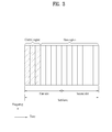
- FIG. 3 is a diagram illustrating a structure of a downlink subframe.
- maximum three(four) OFDM symbols located at the front of the first slot of the subframe correspond to a control region to which a control channel is allocated.
- the other OFDM symbols correspond to a data region to which a physical downlink shared channel (PDSCH) is allocated.
- Examples of the downlink control channel used in the 3GPP LTE include PCFICH (Physical Control Format Indicator CHannel), PDCCH (Physical Downlink Control CHannel), and PHICH (Physical Hybrid ARQ Indicator CHannel).
- the PCFICH is transmitted from the first OFDM symbol of the subframe, and carries information on the number of OFDM symbols used for transmission of the control channel within the subframe.
- the PHICH carries HARQ ACK/NACK (acknowledgement/negative-acknowledgement) in response to uplink transmission.
- the control information transmitted through the PDCCH will be referred to as a downlink control information (DCI).
- DCI includes resource allocation information for a user equipment or user equipment group and other control information.
- the DCI includes uplink/downlink scheduling information, uplink transmission (Tx) power control command, etc.
- the PDCCH carries transport format and resource allocation information of a downlink shared channel (DL-SCH), transport format and resource allocation information of an uplink shared channel (UL-SCH), paging information on a paging channel (PCH), system information on the DL-SCH, resource allocation information of upper layer control message such as random access response transmitted on the PDSCH, a set of transmission power control commands of individual user equipments (UEs) within a user equipment group, a transmission power control command, and activity indication information of voice over Internet protocol (VoIP).
- a plurality of PDCCHs may be transmitted within the control region.
- the user equipment may monitor the plurality of PDCCHs.
- the PDCCH is transmitted on aggregation of one or a plurality of continuous control channel elements (CCEs).
- CCEs continuous control channel elements
- the CCE is a logic allocation unit used to provide a coding rate based on the status of a radio channel to the PDCCH.
- the CCE corresponds to a plurality of resource element groups (REGs).
- the format of the PDCCH and the number of bits of the PDCCH are determined depending on the number of CCEs.
- a base station determines a PDCCH format depending on the DCI to be transmitted to the user equipment, and attaches cyclic redundancy check (CRC) to the control information.
- the CRC is masked (or scrambled) with an identifier (for example, radio network temporary identifier (RNTI)) depending on usage of the PDCCH or user of the PDCCH.
- RNTI radio network temporary identifier
- an identifier for example, cell-RNTI (C-RNTI) of the corresponding user equipment may be masked with the CRC.
- C-RNTI cell-RNTI
- a paging identifier for example, Paging-RNTI (P-RNTI)
- P-RNTI Paging-RNTI
- SIB system information block
- SI-RNTI system information RNTI
- RA-RNTI random access RNTI
- CRC masking includes XOR operation of CRC and RNTI at a bit level.
- FIG. 4 is a diagram illustrating a structure of an uplink subframe.
- the uplink subframe includes a plurality of slots (for example, two).
- Each slot may include a plurality of SC-FDMA symbols, wherein the number of SC-FDMA symbols included in each slot is varied depending on a cyclic prefix (CP) length.
- CP cyclic prefix
- the slot may include SC-FDMA symbols.
- the uplink subframe is divided into a data region and a control region in a frequency domain.
- the data region includes a PUSCH, and is used to transmit a data signal such as voice.
- the control region includes a PUCCH, and is used to transmit control information.
- the control information includes HARQ ACK/NACK, channel quality information (CQI), a precoding matrix indicator (PMI), rank indication (RI), etc.
- Physical resource blocks (PRBs) and virtual resource blocks (VRBs) are defined.
- the physical resource blocks are as illustrated in FIG. 2 .
- the physical resource blocks are defined by N symb DL continuous OFDM symbols and in a time domain and N sc RB continuous subcarriers in a time domain.
- the physical resource blocks are given by numbers 0 ⁇ N RB DL - 1 in the frequency domain.
- the relation between the physical resource block number n PRB and resource elements ( k,l ) of the slot is expressed by the following Equation 1.
- n PRB ⁇ k N sc RB ⁇
- k is a subcarrier index
- N sc RB represents the number of subcarriers included in one resource block.
- the virtual resource blocks have the same size as that of the physical resource blocks.
- Localized type virtual resource blocks (LVRB) and distributed type virtual resource blocks (DVRB) are defined.
- a pair of resource blocks are allocated to two slots of the subframe by a single virtual resource block number n VRB regardless of the type of the virtual resource block.
- FIG. 5 is a diagram illustrating mapping of a virtual resource block (VRB) into a physical resource block (PRB).
- VRB virtual resource block
- PRB physical resource block
- the DVRB is mapped into the PRB through interleaving. In more detail, the DVRB may be mapped into the PRB as expressed by Table 1 below. Table 1 illustrates RB gap values.
- N gap represents a frequency interval (for example, PRB unit) when the VRBs of the same number are mapped into the PRBs of the first slot and the second slot.
- N gap N gap,1
- 50 ⁇ N RB DL ⁇ 110
- the continuous N ⁇ VRB DL VRB numbers constitute a unit for VRB number interleaving.
- N gap N gap,1
- N ⁇ VRB DL N VRB DL
- N gap N gap,2
- N ⁇ VRB DL 2 ⁇ N gap .
- VRB number interleaving of each interleaving unit may be performed using four columns and N row rows.
- N row ⁇ N ⁇ VRB DL / 4 ⁇ P ⁇ .
- P is obtained, wherein P represents a size of a resource block group (RBG).
- the RBG is defined by P continuous resource blocks.
- the VRB numbers are written in a matrix in a row-by-row format, and read out in a column-by-column format.
- the null values are disregarded during reading.
- frequency resource allocation may be indicated per subframe through the PDCCH.
- the physical RB (PRB) of the first half (i.e., the first slot) of the subframe is paired with that of the second half (i.e., the second slot) of the subframe during resource allocation, wherein the PRBs have the same frequency.
- PRB physical RB
- the resource allocation scheme will be described.
- various methods are used for resource allocation as illustrated in Table 2 and Table 3.
- Table 2 illustrates a downlink (DL) resource allocation method
- Table 3 illustrates an uplink (UL) resource allocation method.
- bitmap Bitmap indicates RBG.
- RBG size depends on a system band.
- Type 1 bitmap Bitmap separately indicates RB within RBG subsets. The number of subsets depends on system band. The number of bits is set equally to the case of the type 0. Accordingly, the same DCI format is used to carry information of type 0 or type 1.
- Type 2 continuous allocation A start location of resource blocks and the number of continuous resource blocks are indicated. ⁇ log 2 ⁇ N RB DL ⁇ N RB DL + 1 / 2 ⁇
- N RB DL represents a downlink bandwidth expressed by a multiple of N sc RB .
- N RB DL represents a downlink bandwidth in a unit of RB.
- N RB UL represents an uplink bandwidth expressed by a multiple of N sc RB .
- N RB UL represents an uplink bandwidth in a unit of RB.
- P represents the number of RBs constituting RBG.
- FIG. 6A to FIG. 6C are diagrams illustrating control information formats for resource allocation types 0 to 2 of the existing LTE system and resource allocation examples based on the control information formats.
- the user equipment interprets a resource allocation field based on the detected PDCCH DCI formats.
- the resource allocation field within each PDCCH includes a resource allocation header field and two parts of actual resource block allocation information.
- the PDCCH DCI formats 1, 2 and 2A for resource allocation of the types 0 and 1 have the same format, and are divided from one another through a single bit resource allocation header field existing depending on a downlink system band. In more detail, the resource allocation of the type 0 is indicated by 0, and the resource allocation of the type 1 is indicated by 1.
- the PDCCH DCI formats 1, 2 and 2A are used for the resource allocation of the type 1, whereas the PDCCH DCI formats 1A, 1B, 1C and 1D are used for the resource allocation of the type 2.
- the PDCCH DCI format having the resource allocation of the type 2 does not have a resource allocation header field.
- resource block allocation information includes a bitmap indicating a resource block group (RBG) allocated to the user equipment.
- RBG is a set of continuous PRBs.
- the RBG size (P) depends on the system band as illustrated in Table 4 below.
- N RBG ⁇ N RB DL / P ⁇
- ⁇ N RB DL / P ⁇ RBGs have a size of P.
- N RB DL mod ⁇ P > 0 one of the RBGs is given by a size of N RB DL - P ⁇ ⁇ N RB DL / P ⁇ .
- mod represents modulo operation
- ⁇ ⁇ represents a ceiling function
- ⁇ ⁇ represents a flooring function.
- the size of the bitmap is N RBG , and each bit corresponds to one RBG. All the RBGs are indexed by 0 ⁇ N RBG -1 in a frequency direction, and RBG 0 ⁇ RBG N RBG -1 are mapped from the most significant bit (MSB) of the bitmap into the least significant bit (LSB).
- N RBG sized resource block allocation information indicates resources within the RBG subset in a unit of PRB for the scheduled user equipment.
- the RBG subset p (0 ⁇ p ⁇ P ) starts from RBG p and is configured by the Pth RBG.
- the resource block allocation information includes three fields.
- the first field includes ⁇ log 2 ( P ) ⁇ bits, and indicates RBG subset selected from P RBG subsets.
- the second field includes 1 bit, and indicates shift of resource allocation span within the subset. If a bit value is 1, shift is triggered. If the bit value is not 1, shift is not triggered.
- the third field includes a bitmap, and each bit indicates one PRB within the selected RBG set.
- a bitmap part used to indicate the PRB within the selected RBG subset has a size of N RB TYPE ⁇ 1 , and is defined as expressed by the Equation 2 below.
- N RB TYPE ⁇ 1 ⁇ N RB DL / P ⁇ + ⁇ log 2 P ⁇ - 1
- An addressable PRB number in the selected RBG subset starts from offset ( ⁇ shift ( p )) for the smallest PRB number within the selected RBG subset, and may be mapped into the MSB of the bitmap.
- the resource block allocation information in the resource allocation of the type 2 represents a set of LVRBs or DVRBs continuously allocated to the scheduled user equipment. If resource allocation is signaled by the PDCCH DCI format 1A, 1B or 1D, a 1-bit flag indicates whether the LVRBs or DVRBs are allocated (for example, 0 represents LVRB allocation, and 1 represents DVRB allocation.). On the other hand, if resource allocation is signaled by the PDCCH DCI format 1C, only the DVRBs are always allocated.
- the type 2 resource allocation field includes a resource indication value (RIV), which corresponds to a start resource block RB start and length. The length represents the number of virtual resource blocks allocated continuously.
- RMV resource indication value
- FIG. 7A and FIG. 7B are diagrams illustrating discrete fourier transform spread orthogonal frequency division multiple access (DFT-s-OFDMA) transmitter/receiver.
- DFT-s-OFDMA discrete fourier transform spread orthogonal frequency division multiple access
- a DFT-s-OFDMA scheme is different from the OFDMA scheme in that a plurality of data symbols (i.e., data symbol sequences) are distributed in the frequency domain through DFT precoding prior to IFFT processing.
- the DFT-s-OFDMA scheme is referred to as an SC-FDMA scheme. In this specification, the DFT-s-OFDMA scheme and the SC-FDMA scheme will be used together.
- the DFT-s-OFDMA transmitter 700 includes a constellation mapping module 702, a serial to parallel converter 704, an Nu-point FFT spreading module 706, a symbol-to-subcarrier mapping module 708, an Nc-point IFFT module 710, a cyclic prefix module 712, and a parallel to serial converter 714.
- These modules are illustrated to describe the embodiment of the present invention, and the DFT-s-OFDMA transmitter 700 may further include additional modules. Also, functions of some modules may be united into one module.
- Nu is an input size of the FFT spreading module, and corresponds to the number of scheduled subcarriers.
- Nc corresponds to the number of all subcarriers existing within the system band. Accordingly, the Nu value and DFT input and output size based on the Nu value may be varied within the range of Nu ⁇ Nc depending on data symbols scheduled per scheduling time.
- a signal processing procedure of the DFT-s-OFDMA transmitter 700 will be described as follows. First of all, bit streams are modulated to data symbol sequences (702). Afterwards, the serial data symbol sequences are converted into parallel data symbol sequences as much as Nu. The parallel data symbol sequences of the Nu length are converted into frequency domain sequences of the Nu length through FFT processing of the same size (706). The FFT processing may be performed through Nu-point DFT processing. In this specification, FFT may be referred to as DFT. DFT processing may be referred to as DFT spreading or DFT precoding.
- the frequency domain sequences of the Nu length are mapped into Nu allocated subcarriers among a total of Nc subcarriers, and the other Nc-Nu subcarriers are padded with 0 (708).
- the sequences mapped into the Nc subcarriers are converted into time domain sequences of the Nc length through Nc-point IFFT processing (710).
- cyclic prefix is configured in such a manner that Np samples among the time domain sequences are copied and added to the front of the sequences (712).
- the generated time domain sequences correspond to one transmission symbol and are converted to the serial sequences through the parallel to serial converter (714).
- the serial sequences are transmitted to the receiver through frequency up-conversion. Available subcarriers from the other Nc-Nu subcarriers remaining after being used by the previous user are allocated to the other user, so that the other user transmits the allocated data.
- the receiver 720 includes a serial to parallel converter 722, an Nc-point FFT module 724, a subcarrier-to-symbol mapping module 726, an Nu-point DFT despreading module 728, a parallel to serial converter 730, and a constellation demapping module 732.
- RF/ADC analog to digital converter
- serial-to-parallel converter 218 serial-to-parallel converter
- CP cyclic prefix
- DFT M-point discrete fourier transform
- subcarrier demapping/equalization module 224 subcarrier demapping/equalization module 224
- parallel-to-digital converter 228, and a detection module 230 Since a signal processing procedure of the receiver is in reverse order of the transmitter 700, its detailed description may refer to the description of FIG. 7A .
- the OFDMA scheme is used in a downlink, whereas the SC-FDMA scheme is used in an uplink.
- the OFDMA transmitter corresponds to the block diagram of FIG. 7A excluding the Nu-point FFT spreading module 706, and the OFDMA receiver corresponds to the block diagram of FIG. 7B excluding the Nu-point DFT despreading module 728.
- the LTE-A since Rel-10 system allows allocation of a plurality of discontinuous frequency resources as well as one continuous frequency resource to one user equipment in the uplink.
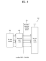
- FIG. 8 is a block diagram illustrating a localized DFT-s-OFDMA transmitter.
- FIG. 8 corresponds to a method for resource allocation in the existing LTE.
- the frequency domain sequences output from the DFT module 806 are mapped into continuous subcarriers within the system band.
- the frequency domain sequences of the Nu length are mapped into Nu continuous subcarriers. Since the method of FIG. 8 allows data transmission through continuous subcarriers at a given time, scheduling flexibility may be deteriorated. For example, if the transmitter and the receiver have good radio channel response properties in a plurality of frequency domains spaced apart from one another at a random time, this method does not allow data transmission to the frequency domains, which are spaced apart from one another, at the same time.
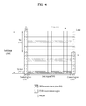
- FIG. 9 is a block diagram illustrating a clustered DFT-s-OFDMA transmitter.
- FIG. 9 corresponds to a method for resource allocation, which is additionally used in the LTE-A.
- a user equipment of the LTE-A may use the method of FIG. 8 or the method of FIG. 9 based on resource allocation information.
- the frequency domain sequences output from the DFT module 906 are mapped into the system band irregularly and discontinuously (908).
- the localized DFT-s-OFDMA scheme is independently applied to the plurality of frequency domains spaced apart from one another.
- each resource set (or frequency band) to which the localized DFT-s-OFDMA scheme is applied will be referred to as a cluster.
- the cluster includes one or more continuous subcarriers. Accordingly, in this method, a plurality of data symbols which have been processed by DFT precoding are mapped into the continuous subcarriers within M( ⁇ 1) clusters spaced apart from one another in the frequency domain.
- FIG. 9 illustrates three clusters.
- Sizes for example, subcarriers, RB or the number of RBGs
- a PAPR value of a transmitting signal is greater than that of the localized DFT-s-OFDMA scheme if the value of M is greater than 1. However, if the value of M is set within a small range, a PAPR value smaller than that of the OFDMA scheme is ensured and at the same time scheduling flexibility can be improved.
- UL RA type N a method for convenience, referred to as UL RA type N
- various methods for efficiently signaling the UL RA type N have been discussed in the art.
- a method for using a bitmap separately indicating UL RB (or RBG) such as DL RA type 0 has been suggested. According to this method, perfect the scheduling freedom is ensured during discontinuous resource allocation. However, if there are n RBs (or RBGs) in UL band, since RA field of n bits is required, the amount of control information may be increased extremely. Moreover, considering that a size of the RA field for existing PUSCH scheduling is defined as ⁇ log 2 ⁇ N RB UL ⁇ N RB UL + 1 / 2 ⁇ , a new DCI format should be defined to support this method.
- the second method a method for restricting a resource region to which each cluster may be allocated while reusing the existing continuous allocation method (RA type 2) has been suggested.
- the size of the RA field may be given by 2 ⁇ ⁇ log 2 ⁇ N RBG Cluster Span ⁇ N RBG Cluster Span + 1 / 2 ⁇ .
- N RBG Cluster Span represents a size of a region to which each cluster may be allocated, and has a size of RBG unit. According to this method, as the size of N RBG Cluster Span is adjusted, discontinuous resource allocation may be performed using the existing RA field. However, since the region to which each cluster may be allocated is restricted, a problem occurs in that the scheduling freedom is reduced.
- the present invention suggests that a combinatorial index corresponding to a plurality of resource sets allocated discontinuously should be used.
- the combinatorial index may be included in the RA field of the DCI format for PUSCH scheduling.
- the combinatorial index is used to indicate that specific combinatorial indexes are selected from all combinatorial indexes.
- ⁇ S 0 , S 1 ⁇ corresponds to the first resource set
- ⁇ S 2 , S 3 ⁇ corresponds to the second resource set
- the correspondence relation may be defined differently. A method for resource allocation based on combinatorial indexes will later be described in more detail.
- N RB UL a total number of RBs corresponding to all UL system bandwidths or UL bandwidths available for resource allocation.
- N RB UL a total number of RBs corresponding to all UL system bandwidths or UL bandwidths available for resource allocation.
- N RBG UL may be given by ⁇ N RB UL / P ⁇ (or, ceiling N RB UL / P ) .
- ⁇ x ⁇ or ceiling(x) represents a minimum integer greater than or equal to x.
- N RBG UL may be given by ⁇ N RB UL / P ⁇ (or floor N RB UL / P ) or round N RB UL / P depending on definition and size of the resource allocation field.
- ⁇ x ⁇ or floor(x) represents a maximum integer smaller than or equal to x.
- round(x) means round-off for x.
- M may be set to all the user equipments equally (that is, cell-specifically), or may be set independently per user equipment (that is, UE-specifically).
- FIG. 10 is a diagram illustrating an example of RBG indexing based RBG map for resource allocation.
- the RBG includes two RBs.
- RB #1 ⁇ #20 is grouped into RBG #1 ⁇ #10.
- the RBG is used as the basic UL resource allocation unit.
- FIG. 10 illustrates that RB indexes and RBG indexes start from 1, they may be defined such that they start from 0.
- This method illustrates a method for allocating a plurality of discontinuous uplink resource sets (for example, RBG clusters) based on RBG indexing.
- a starting RBG index and an ending RBG index of the RBG clusters allocated to the user equipment will be referred to as S and E, respectively.
- a starting RBG index and an ending RBG index of the mth RBG set will be referred to as S m and E m , respectively.
- S m and E m a starting RBG index and an ending RBG index of the mth RBG set.
- restriction of s i ⁇ s i +1 may be considered.
- restriction of s i ⁇ s i +1 is considered, a problem occurs in that a resource set configured by one RBG cannot be allocated.
- Method 1-1 Indication of starting/ending-rear RBG of RBG cluster
- FIG. 11 is a diagram illustrating a method for resource allocation according to the method 1-1.
- this method is based on RBG indexing, and ⁇ S m , E m +1 ⁇ (that is, starting RBG index and ending-rear RBG index) is notified to each of M RBG clusters, which are allocated to the user equipment, among a total of N RBG RBGs.
- a virtual RBG may additionally be defined at the rear (high RBG index direction) of the last RBG index as illustrated in FIG. 11 .
- actual resource allocation cannot be performed and is used for indexing only.
- a combinatorial index r for signaling resource allocation of M RBG clusters may be expressed as follows.
- s i i 0 M ⁇ - 1 ⁇ 1 ⁇ s i ⁇ N + 1
- the combinatorial index r for signaling resource allocation of M RBG clusters may be expressed as follows.
- s i i 0 M ⁇ - 1 ⁇ 0 ⁇ s i ⁇ N
- x y represents x ⁇ x - 1 ⁇ x - y + 1 y ⁇ y - 1 ⁇ 1 .
- N may be given by the following Equation.
- N RB UL represents the number of resource blocks of the uplink band.
- P represents the number of resource blocks constituting RBG.
- ⁇ ⁇ represents a ceiling function.
- Table 5 illustrates RBG size (P) depending on the system band.
- FIG. 12 is a diagram illustrating a method for resource allocation according to the method 1-2.
- this method is based on RBG indexing, and ⁇ S m -1, E m ⁇ (that is, starting-front RBG index and ending RBG index) is notified to each of M RBG clusters, which are allocated to the user equipment, among a total of N RBG RBGs.
- a virtual RBG may additionally be defined at the front (low RBG index direction) of the first RBG index as illustrated in FIG. 12 .
- actual resource allocation cannot be performed and is used for indexing only.
- a combinatorial index r for signaling resource allocation of M RBG clusters may be expressed as given by the Equation 4. Also, when N+1 RBG indexes from 0 to N are defined, the combinatorial index r for signaling resource allocation of M RBG clusters may be expressed as given by the Equation 5.
- This method illustrates a method for allocating a plurality of discontinuous uplink resource sets (for example, RBG clusters) based on RBG border indexing.
- a starting RBG border index and an ending RBG border index of the RBG clusters allocated to the user equipment will be referred to as SB and EB, respectively.
- a starting RBG border index and an ending RBG border index of the mth RBG set will be referred to as SB m and EB m , respectively.
- SB m and EB m a starting RBG border index and an ending RBG border index of the mth RBG set.
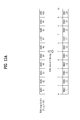
- FIGs. 13A and 13B are diagrams illustrating a method for resource allocation according to the method 2.
- this method is based on RBG border indexing, and ⁇ SB m , EB m ⁇ (that is, starting RBG border index and ending RBG border index) is notified to each of M RBG clusters, which are allocated to the user equipment, among a total of N RBG RBGs.
- a combinatorial index r for signaling resource allocation of M RBG clusters may be expressed as follows.
- s i i 0 M ⁇ - 1 ⁇ 1 ⁇ s i ⁇ N + 1
- x y represents x ⁇ x - 1 ⁇ x - y + 1 y ⁇ y - 1 ⁇ 1 .
- the combinatorial index r for signaling resource allocation of M RBG clusters may be expressed as follows.
- s i i 0 M ⁇ - 1 ⁇ 0 ⁇ s i ⁇ N
- x y represents x ⁇ x - 1 ⁇ x - y + 1 y ⁇ y - 1 ⁇ 1 .
- FIG. 14 is a diagram illustrating an example of uplink transmission according to the embodiment of the present invention.
- the user equipment receives resource allocation information including combinatorial indexes from a network node (for example, base station or relay) (S1402).
- a field for resource allocation information is included in the DCI, and may be received through a downlink control channel (for example, PDCCH). If a PDCCH having a DCI format for PUSCH scheduling is detected from a subframe n, the user equipment performs a process for PUSCH transmission based on PDCCH information at the subframe n+4. To this end, the user equipment interprets resource allocation information.
- the uplink signal includes uplink-shared channel (UL-SCH) data and/or control information.
- the user equipment performs uplink transmission by using the resource set allocated from the network node (for example, base station or relay) (S1408).
- the uplink transmission may be performed through an uplink shared channel (for example, PUSCH).
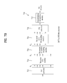
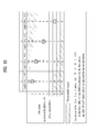
- FIG. 15 illustrates an example of resource allocation information according to the embodiment of the present invention.
- the number of RBGs is 9 and two resource sets (for example, RBG clusters) are allocated.
- Each of the resource sets is configured by continuous resources (for example, RBG).
- the methods are used as follows to transmit the uplink signal.
- RBG #3 and RBG #6 ⁇ 8 are used to transmit the uplink signal.
- RBG #3 and RBG #6 ⁇ 8 are used to transmit the uplink signal.
- the LTE-A system may support both continuous uplink resource allocation and discontinuous uplink resource allocation. These two resource allocation methods may be signaled through the same DCI format.
- a resource allocation type which is actually used, may be identified using a flag bit. For example, in the same manner as the DL RA type 0/1, a flag of 1 bit is applied to RA header of the DCI format for PUSCH scheduling, and then continuous resource allocation and discontinuous resource allocation may be signaled selectively through the flag of 1 bit.
- FIG. 16 is a diagram illustrating a base station and a user equipment, which may be applied to one embodiment of the present invention.
- the block diagram of the base station-user equipment may be replaced with a block diagram of base station-relay or relay-user equipment.
- a wireless communication system includes a base station (BS) 110 and a user equipment (UE) 120.
- the base station 110 includes a processor 112, a memory 114, and a radio frequency (RF) unit 116.
- the processor 112 may be configured to implement the procedures and/or the methods suggested in the present invention.
- the memory 114 is connected with the processor 112 and stores various kinds of information related to the operation of the processor 112.
- the RF unit 116 is connected with the processor 112 and transmits and/or receives a radio signal.
- the user equipment 120 includes a processor 122, a memory 124, and a radio frequency (RF) unit 126.
- the processor 122 may be configured to implement the procedures and/or the methods suggested in the present invention.
- the memory 124 is connected with the processor 122 and stores various kinds of information related to the operation of the processor 122.
- the RF unit 126 is connected with the processor 122 and transmits and/or receives a radio signal.
- the base station 110 and/or the user equipment 120 may have a single antenna or multiple antennas.
- the embodiments of the present invention have been described based on the data transmission and reception between the base station and the user equipment.
- a specific operation which has been described as being performed by the base station may be performed by an upper node of the base station as the case may be.
- various operations performed for communication with the user equipment in the network which includes a plurality of network nodes along with the base station may be performed by the base station or network nodes other than the base station.
- the base station may be replaced with terms such as a fixed station, Node B, eNode B (eNB), and access point.
- the user equipment may be replaced with terms such as mobile station (MS) and mobile subscriber station (MSS).
- the embodiments according to the present invention may be implemented by various means, for example, hardware, firmware, software, or their combination. If the embodiment according to the present invention is implemented by hardware, the embodiment of the present invention may be implemented by one or more application specific integrated circuits (ASICs), digital signal processors (DSPs), digital signal processing devices (DSPDs), programmable logic devices (PLDs), field programmable gate arrays (FPGAs), processors, controllers, microcontrollers, microprocessors, etc.
- ASICs application specific integrated circuits
- DSPs digital signal processors
- DSPDs digital signal processing devices
- PLDs programmable logic devices
- FPGAs field programmable gate arrays
- processors controllers, microcontrollers, microprocessors, etc.
- the embodiment of the present invention may be implemented by a type of a module, a procedure, or a function, which performs functions or operations described as above.
- a software code may be stored in a memory unit and then may be driven by a processor.
- the memory unit may be located inside or outside the processor to transmit and receive data to and from the processor through various means which are well known.
- the present invention can be used for a wireless communication device such as a user equipment, a relay and a base station.
Landscapes
- Engineering & Computer Science (AREA)
- Signal Processing (AREA)
- Computer Networks & Wireless Communication (AREA)
- Physics & Mathematics (AREA)
- Discrete Mathematics (AREA)
- General Physics & Mathematics (AREA)
- Mathematical Physics (AREA)
- Mobile Radio Communication Systems (AREA)
- Digital Transmission Methods That Use Modulated Carrier Waves (AREA)
Priority Applications (1)
| Application Number | Priority Date | Filing Date | Title |
|---|---|---|---|
| EP14162051.8A EP2763344A3 (de) | 2010-05-24 | 2011-05-24 | Verfahren und Vorrichtung zur Zuweisung diskontinuierlicher Uplink-Ressourcen |
Applications Claiming Priority (2)
| Application Number | Priority Date | Filing Date | Title |
|---|---|---|---|
| US34779410P | 2010-05-24 | 2010-05-24 | |
| PCT/KR2011/003792 WO2011149244A2 (ko) | 2010-05-24 | 2011-05-24 | 불연속적 상향링크 자원 할당을 위한 방법 및 장치 |
Related Child Applications (1)
| Application Number | Title | Priority Date | Filing Date |
|---|---|---|---|
| EP14162051.8A Division EP2763344A3 (de) | 2010-05-24 | 2011-05-24 | Verfahren und Vorrichtung zur Zuweisung diskontinuierlicher Uplink-Ressourcen |
Publications (2)
| Publication Number | Publication Date |
|---|---|
| EP2579662A2 true EP2579662A2 (de) | 2013-04-10 |
| EP2579662A4 EP2579662A4 (de) | 2014-10-15 |
Family
ID=45004543
Family Applications (2)
| Application Number | Title | Priority Date | Filing Date |
|---|---|---|---|
| EP11786876.0A Withdrawn EP2579662A4 (de) | 2010-05-24 | 2011-05-24 | Verfahren und vorrichtung zur zuweisung diskontinuierlicher uplink-ressourcen |
| EP14162051.8A Withdrawn EP2763344A3 (de) | 2010-05-24 | 2011-05-24 | Verfahren und Vorrichtung zur Zuweisung diskontinuierlicher Uplink-Ressourcen |
Family Applications After (1)
| Application Number | Title | Priority Date | Filing Date |
|---|---|---|---|
| EP14162051.8A Withdrawn EP2763344A3 (de) | 2010-05-24 | 2011-05-24 | Verfahren und Vorrichtung zur Zuweisung diskontinuierlicher Uplink-Ressourcen |
Country Status (6)
| Country | Link |
|---|---|
| US (6) | US8611299B2 (de) |
| EP (2) | EP2579662A4 (de) |
| JP (3) | JP5406382B2 (de) |
| KR (1) | KR101615985B1 (de) |
| CN (2) | CN103945542A (de) |
| WO (1) | WO2011149244A2 (de) |
Families Citing this family (74)
| Publication number | Priority date | Publication date | Assignee | Title |
|---|---|---|---|---|
| KR101513044B1 (ko) * | 2008-08-05 | 2015-04-17 | 엘지전자 주식회사 | Papr을 줄이기 위한 무선 접속 방식 |
| KR101615985B1 (ko) | 2010-05-24 | 2016-05-12 | 엘지전자 주식회사 | 불연속적 상향링크 자원 할당을 위한 방법 및 장치 |
| EP2584828B1 (de) | 2010-06-21 | 2019-03-13 | Sun Patent Trust | Meldung von information bezüglich zugeordneter ressourcen von einer basisstation an ein endgerät |
| GB2496908B (en) | 2011-11-28 | 2017-04-26 | Ubiquisys Ltd | Power management in a cellular system |
| KR101767021B1 (ko) * | 2011-12-28 | 2017-08-09 | 후지쯔 가부시끼가이샤 | 물리적 다운링크 제어 채널의 검색 공간의 매핑 방법 및 장치 |
| US9408217B2 (en) | 2012-01-17 | 2016-08-02 | Qualcomm Incorporated | Maximum power reduction for interference control in adjacent channels |
| WO2013144950A1 (en) | 2012-03-25 | 2013-10-03 | Intucell Ltd. | System and method for optimizing performance of a communication network |
| IL222709A (en) | 2012-10-25 | 2016-02-29 | Intucell Ltd | A method and mechanism for coordinating interference between communications cells in solar systems |
| WO2014067583A1 (en) * | 2012-11-02 | 2014-05-08 | Huawei Technologies Co., Ltd. | Resource allocation signalling in a network control |
| US9014004B2 (en) | 2012-12-04 | 2015-04-21 | Cisco Technology, Inc. | Method for managing load balance in a cellular heterogeneous network |
| US9167444B2 (en) | 2012-12-04 | 2015-10-20 | Cisco Technology, Inc. | Method for managing heterogeneous cellular networks |
| US9143995B2 (en) | 2013-02-22 | 2015-09-22 | Cisco Technology, Inc. | System and method for hand-in disambiguation using user equipment WiFi location in a network environment |
| IL224926A0 (en) | 2013-02-26 | 2013-07-31 | Valdimir Yanover | A method and system for allocating resources in the @telecommunications@cellphone network |
| GB2518584B (en) | 2013-07-09 | 2019-12-25 | Cisco Tech Inc | Power setting |
| JP2015076700A (ja) * | 2013-10-08 | 2015-04-20 | 株式会社Nttドコモ | 無線装置、無線制御装置及び通信制御方法 |
| US9414310B2 (en) | 2013-11-27 | 2016-08-09 | Cisco Technology, Inc. | System and method for small cell power control in an enterprise network environment |
| US9813179B2 (en) | 2014-01-29 | 2017-11-07 | Mediatek Inc. | Method for cancelling a data transmission of a neighboring cell |
| US9655102B2 (en) | 2014-06-20 | 2017-05-16 | Cisco Technology, Inc. | Interference control in a cellular communications network |
| US10225698B2 (en) | 2014-07-03 | 2019-03-05 | Cisco Technology, Inc. | System and method for providing message delivery and paging to a group of users in a network environment |
| US9516640B2 (en) | 2014-08-01 | 2016-12-06 | Cisco Technology, Inc. | System and method for a media access control scheduler for a long term evolution unlicensed network environment |
| US9867187B2 (en) * | 2014-08-04 | 2018-01-09 | Qualcomm Incorporated | Techniques for configuring uplink channel transmissions using shared radio frequency spectrum band |
| US9402195B2 (en) | 2014-09-07 | 2016-07-26 | Cisco Technology, Inc. | Operation of base station in a cellular communications network |
| US10462699B2 (en) | 2014-09-08 | 2019-10-29 | Cisco Technology, Inc. | System and method for internet protocol version-based multiple access point name support in a network environment |
| US9717068B2 (en) | 2014-09-09 | 2017-07-25 | Cisco Technology, Inc. | System and method for supporting cell updates within a small cell cluster for idle mobility in cell paging channel mode |
| US9844070B2 (en) | 2014-09-10 | 2017-12-12 | Cisco Technology, Inc. | System and method for decoupling long term evolution media access control scheduling from subframe rate procedures |
| US9729396B2 (en) | 2014-11-04 | 2017-08-08 | Cisco Technology, Inc. | System and method for providing dynamic radio access network orchestration |
| US9699725B1 (en) | 2014-11-07 | 2017-07-04 | Cisco Technology, Inc. | System and method for providing power saving mode enhancements in a network environment |
| US9730156B1 (en) | 2014-11-07 | 2017-08-08 | Cisco Technology, Inc. | System and method for providing power saving mode enhancements in a network environment |
| US9843687B2 (en) | 2014-11-09 | 2017-12-12 | Cisco Technology, Inc. | System and method for radio aware traffic management based wireless authorization |
| US9629042B2 (en) | 2014-12-05 | 2017-04-18 | Cisco Technology, Inc. | System and method for providing collaborative neighbor management in a network environment |
| US9686798B1 (en) | 2015-01-14 | 2017-06-20 | Cisco Technology, Inc. | System and method for providing collision-avoided physical downlink control channel resource allocation in a network environment |
| US9621362B2 (en) | 2015-02-03 | 2017-04-11 | Cisco Technology, Inc. | System and method for providing policy charging and rules function discovery in a network environment |
| US9699601B2 (en) | 2015-04-06 | 2017-07-04 | Cisco Technology, Inc. | System and method for managing interference in a network environment based on user presence |
| CN106162889A (zh) * | 2015-04-10 | 2016-11-23 | 中兴通讯股份有限公司 | 一种实现资源分配的方法和装置 |
| US9918314B2 (en) | 2015-04-14 | 2018-03-13 | Cisco Technology, Inc. | System and method for providing uplink inter cell interference coordination in a network environment |
| CN106332286B (zh) * | 2015-06-30 | 2022-01-28 | 中兴通讯股份有限公司 | 频谱资源分配方法及装置 |
| US10244422B2 (en) | 2015-07-16 | 2019-03-26 | Cisco Technology, Inc. | System and method to manage network utilization according to wireless backhaul and radio access network conditions |
| US9648569B2 (en) | 2015-07-25 | 2017-05-09 | Cisco Technology, Inc. | System and method to facilitate small cell uplink power control in a network environment |
| US9860852B2 (en) | 2015-07-25 | 2018-01-02 | Cisco Technology, Inc. | System and method to facilitate small cell uplink power control in a network environment |
| US9854535B2 (en) | 2015-07-28 | 2017-12-26 | Cisco Technology, Inc. | Determining fractional frequency reuse power levels for downlink transmissions |
| US9854536B2 (en) | 2015-08-03 | 2017-12-26 | Cisco Technology, Inc. | User equipment power level selection for downlink transmissions |
| US9848389B2 (en) | 2015-08-03 | 2017-12-19 | Cisco Technology, Inc. | Selecting cells for downlink inter-cell interference coordination |
| US10154415B2 (en) | 2015-08-04 | 2018-12-11 | Cisco Technology, Inc. | Resource adaptation for frequency domain downlink inter-cell interference coordination |
| US9967067B2 (en) | 2015-09-08 | 2018-05-08 | Cisco Technology, Inc. | Serving noise/macro interference limited user equipment for downlink inter-cell interference coordination |
| CN106656444B (zh) * | 2015-11-03 | 2019-03-26 | 中兴通讯股份有限公司 | 一种资源分配方法及装置 |
| US9826408B2 (en) | 2015-12-07 | 2017-11-21 | Cisco Technology, Inc. | System and method to provide uplink interference coordination in a network environment |
| US10143002B2 (en) | 2016-01-12 | 2018-11-27 | Cisco Technology, Inc. | System and method to facilitate centralized radio resource management in a split radio access network environment |
| US9813970B2 (en) | 2016-01-20 | 2017-11-07 | Cisco Technology, Inc. | System and method to provide small cell power control and load balancing for high mobility user equipment in a network environment |
| EP4187832A1 (de) * | 2016-01-29 | 2023-05-31 | Ntt Docomo, Inc. | Benutzerendgerät, funkbasisstation und funkkommunikationsverfahren |
| US10420134B2 (en) | 2016-02-02 | 2019-09-17 | Cisco Technology, Inc. | System and method to facilitate subframe scheduling in a split medium access control radio access network environment |
| JP7120627B2 (ja) * | 2016-02-02 | 2022-08-17 | 日本電気株式会社 | 基地局、ue、及び方法 |
| EP3404973B1 (de) * | 2016-02-04 | 2021-08-04 | Huawei Technologies Co., Ltd. | Datensendeverfahren, datenempfangsverfahren, benutzergerät und basisstation |
| US10091697B1 (en) | 2016-02-08 | 2018-10-02 | Cisco Technology, Inc. | Mitigation of uplink interference within heterogeneous wireless communications networks |
| US9801127B2 (en) | 2016-02-23 | 2017-10-24 | Cisco Technology, Inc. | System and method to provide power management for a multimode access point in a network environment |
| EP3866541B1 (de) * | 2016-03-18 | 2023-12-27 | Huawei Technologies Co., Ltd. | Netzwerkknoten, benutzervorrichtung und verfahren dafür |
| WO2017166246A1 (en) * | 2016-03-31 | 2017-10-05 | Lenovo Innovations Limited (Hong Kong) | Interlace determination for device |
| US10863505B2 (en) * | 2016-08-26 | 2020-12-08 | Qualcomm Incorporated | Data channel resource allocation |
| CN108811095B (zh) * | 2017-04-28 | 2024-04-12 | 华为技术有限公司 | 一种参数配置方法和装置 |
| EP3641254B1 (de) * | 2017-06-15 | 2023-12-20 | Ntt Docomo, Inc. | Benutzerendgerät und drahtloskommunikationsverfahren |
| EP3646947B1 (de) * | 2017-06-30 | 2022-03-16 | Showa Denko K.K. | Füllstoff für die flüssigchromatographie und verfahren zu dessen herstellung |
| CN117202362A (zh) * | 2017-09-28 | 2023-12-08 | 诺基亚技术有限公司 | 指示连续的资源分配 |
| CN121645520A (zh) | 2017-11-10 | 2026-03-10 | 华为技术有限公司 | 一种通信方法、装置以及系统 |
| CN111357352A (zh) * | 2017-11-17 | 2020-06-30 | 株式会社Ntt都科摩 | 用户终端以及无线通信方法 |
| KR101954433B1 (ko) | 2018-01-11 | 2019-03-05 | 엘지전자 주식회사 | 무선 통신 시스템에서 단말의 하향링크 신호 수신 방법 및 상기 방법을 이용하는 단말 |
| ES3036068T3 (en) * | 2018-01-13 | 2025-09-12 | Wilus Inst Standards & Tech Inc | Resource allocation method, device and system of wireless communication system |
| JP2019198014A (ja) * | 2018-05-10 | 2019-11-14 | シャープ株式会社 | 端末装置、基地局装置、および、通信方法 |
| CN110636610B (zh) * | 2018-06-21 | 2022-08-26 | 华为技术有限公司 | 一种通信方法及装置 |
| WO2021029437A1 (en) * | 2019-08-09 | 2021-02-18 | Sharp Kabushiki Kaisha | Terminal devices, base station devices, and communication methods |
| US12232132B2 (en) | 2019-08-23 | 2025-02-18 | Lg Electronics Inc. | Method and user equipment for receiving downlink signal, and method and base station for transmitting downlink signal |
| CN112566251B (zh) * | 2019-09-26 | 2025-01-17 | 苹果公司 | 用于多trp传输的下行链路控制 |
| JP2021022944A (ja) * | 2020-10-28 | 2021-02-18 | 日本電気株式会社 | 方法 |
| WO2022151236A1 (zh) * | 2021-01-14 | 2022-07-21 | Oppo广东移动通信有限公司 | 资源确定方法、装置、设备及存储介质 |
| CN117956617A (zh) * | 2023-01-31 | 2024-04-30 | 中兴通讯股份有限公司 | 一种物理信道处理方法、装置及存储介质 |
| WO2025170324A1 (ko) * | 2024-02-06 | 2025-08-14 | 엘지전자 주식회사 | 무선통신 시스템에서 장치의 동작 방법 및 상기 방법을 이용하는 장치 |
Family Cites Families (13)
| Publication number | Priority date | Publication date | Assignee | Title |
|---|---|---|---|---|
| KR20080073196A (ko) | 2007-02-05 | 2008-08-08 | 엘지전자 주식회사 | Mimo 시스템에서 효율적인 채널 품질 정보 전송 방법 |
| KR101049138B1 (ko) * | 2007-03-19 | 2011-07-15 | 엘지전자 주식회사 | 이동 통신 시스템에서, 수신확인신호 수신 방법 |
| US9137821B2 (en) | 2007-05-02 | 2015-09-15 | Qualcomm Incorporated | Flexible signaling of resources on a control channel |
| KR100908063B1 (ko) | 2007-06-13 | 2009-07-15 | 엘지전자 주식회사 | 이동 통신 시스템에서 확산신호를 송신하는 방법 |
| KR101447745B1 (ko) | 2007-08-08 | 2014-10-06 | 삼성전자주식회사 | 단일 캐리어 주파수 분할 다중 접속 시스템에서의 상향 링크 자원 정보 송수신 방법 및 장치 |
| US8559381B2 (en) * | 2008-01-07 | 2013-10-15 | Nokia Corporation | Method, apparatus and computer program to map a downlink resource to a related uplink transmission |
| KR101563000B1 (ko) * | 2008-03-17 | 2015-10-26 | 엘지전자 주식회사 | 무선 통신 시스템에서 상향링크 데이터 전송 방법 |
| US8493835B2 (en) | 2008-03-26 | 2013-07-23 | Qualcomm, Incorporated | Method and apparatus for mapping virtual resources to physical resources in a wireless communication system |
| KR100921467B1 (ko) | 2008-06-19 | 2009-10-13 | 엘지전자 주식회사 | 셀룰라 다중반송파 시스템에서 조밀도를 조절하는 자원할당시그널링 방식 |
| US9055576B2 (en) * | 2009-10-08 | 2015-06-09 | Qualcomm Incorporated | Uplink resource allocation for LTE advanced |
| KR101866577B1 (ko) * | 2010-01-11 | 2018-06-11 | 삼성전자주식회사 | 통신 시스템의 업링크에서 낮은 레이턴시 송신을 가능하게 하는 장치 및 방법 |
| KR101615985B1 (ko) * | 2010-05-24 | 2016-05-12 | 엘지전자 주식회사 | 불연속적 상향링크 자원 할당을 위한 방법 및 장치 |
| CN103081385B (zh) * | 2010-09-14 | 2016-02-17 | Lg电子株式会社 | 用于上行链路资源分配的方法和装置 |
-
2011
- 2011-05-24 KR KR1020127005775A patent/KR101615985B1/ko active Active
- 2011-05-24 EP EP11786876.0A patent/EP2579662A4/de not_active Withdrawn
- 2011-05-24 US US13/577,623 patent/US8611299B2/en active Active
- 2011-05-24 WO PCT/KR2011/003792 patent/WO2011149244A2/ko not_active Ceased
- 2011-05-24 CN CN201410119645.7A patent/CN103945542A/zh active Pending
- 2011-05-24 EP EP14162051.8A patent/EP2763344A3/de not_active Withdrawn
- 2011-05-24 JP JP2012541037A patent/JP5406382B2/ja active Active
- 2011-05-24 CN CN201180006298.1A patent/CN102754504B/zh active Active
-
2013
- 2013-10-10 US US14/051,280 patent/US9191944B2/en active Active
- 2013-10-31 JP JP2013226448A patent/JP5628993B2/ja not_active Expired - Fee Related
- 2013-11-04 US US14/071,319 patent/US9210701B2/en active Active
-
2014
- 2014-03-14 US US14/214,085 patent/US9226286B2/en active Active
- 2014-10-02 JP JP2014203590A patent/JP5932931B2/ja active Active
-
2015
- 2015-12-08 US US14/962,487 patent/US9497759B2/en active Active
-
2016
- 2016-10-18 US US15/296,948 patent/US10039090B2/en active Active
Also Published As
| Publication number | Publication date |
|---|---|
| US20140198756A1 (en) | 2014-07-17 |
| CN103945542A (zh) | 2014-07-23 |
| JP2015027101A (ja) | 2015-02-05 |
| US20160095100A1 (en) | 2016-03-31 |
| JP5406382B2 (ja) | 2014-02-05 |
| WO2011149244A2 (ko) | 2011-12-01 |
| JP5932931B2 (ja) | 2016-06-08 |
| US20120307771A1 (en) | 2012-12-06 |
| EP2579662A4 (de) | 2014-10-15 |
| CN102754504A (zh) | 2012-10-24 |
| WO2011149244A3 (ko) | 2012-04-19 |
| KR101615985B1 (ko) | 2016-05-12 |
| EP2763344A2 (de) | 2014-08-06 |
| JP2014060759A (ja) | 2014-04-03 |
| US20140056268A1 (en) | 2014-02-27 |
| CN102754504B (zh) | 2015-05-13 |
| JP5628993B2 (ja) | 2014-11-19 |
| JP2013511940A (ja) | 2013-04-04 |
| EP2763344A3 (de) | 2014-10-15 |
| US9210701B2 (en) | 2015-12-08 |
| KR20130075714A (ko) | 2013-07-05 |
| US9191944B2 (en) | 2015-11-17 |
| US9226286B2 (en) | 2015-12-29 |
| US8611299B2 (en) | 2013-12-17 |
| US9497759B2 (en) | 2016-11-15 |
| US20140036840A1 (en) | 2014-02-06 |
| US20170041910A1 (en) | 2017-02-09 |
| US10039090B2 (en) | 2018-07-31 |
Similar Documents
| Publication | Publication Date | Title |
|---|---|---|
| US10039090B2 (en) | Method and apparatus for allocation of discontinuous uplink resource | |
| EP2618505B1 (de) | Verfahren und vorrichtung zur zuweisung von uplink-ressourcen |
Legal Events
| Date | Code | Title | Description |
|---|---|---|---|
| PUAI | Public reference made under article 153(3) epc to a published international application that has entered the european phase |
Free format text: ORIGINAL CODE: 0009012 |
|
| 17P | Request for examination filed |
Effective date: 20120731 |
|
| AK | Designated contracting states |
Kind code of ref document: A2 Designated state(s): AL AT BE BG CH CY CZ DE DK EE ES FI FR GB GR HR HU IE IS IT LI LT LU LV MC MK MT NL NO PL PT RO RS SE SI SK SM TR |
|
| DAX | Request for extension of the european patent (deleted) | ||
| A4 | Supplementary search report drawn up and despatched |
Effective date: 20140915 |
|
| RIC1 | Information provided on ipc code assigned before grant |
Ipc: H04L 5/00 20060101AFI20140909BHEP |
|
| 17Q | First examination report despatched |
Effective date: 20150715 |
|
| STAA | Information on the status of an ep patent application or granted ep patent |
Free format text: STATUS: EXAMINATION IS IN PROGRESS |
|
| STAA | Information on the status of an ep patent application or granted ep patent |
Free format text: STATUS: THE APPLICATION IS DEEMED TO BE WITHDRAWN |
|
| 18D | Application deemed to be withdrawn |
Effective date: 20170425 |