EP2579691A1 - Intelligenter Schalter für Energieverwaltung und entsprechendes Verfahren - Google Patents
Intelligenter Schalter für Energieverwaltung und entsprechendes Verfahren Download PDFInfo
- Publication number
- EP2579691A1 EP2579691A1 EP20120187221 EP12187221A EP2579691A1 EP 2579691 A1 EP2579691 A1 EP 2579691A1 EP 20120187221 EP20120187221 EP 20120187221 EP 12187221 A EP12187221 A EP 12187221A EP 2579691 A1 EP2579691 A1 EP 2579691A1
- Authority
- EP
- European Patent Office
- Prior art keywords
- switch
- switch module
- modules
- power
- power status
- Prior art date
- Legal status (The legal status is an assumption and is not a legal conclusion. Google has not performed a legal analysis and makes no representation as to the accuracy of the status listed.)
- Granted
Links
Images




Classifications
-
- H—ELECTRICITY
- H05—ELECTRIC TECHNIQUES NOT OTHERWISE PROVIDED FOR
- H05B—ELECTRIC HEATING; ELECTRIC LIGHT SOURCES NOT OTHERWISE PROVIDED FOR; CIRCUIT ARRANGEMENTS FOR ELECTRIC LIGHT SOURCES, IN GENERAL
- H05B47/00—Circuit arrangements for operating light sources in general, i.e. where the type of light source is not relevant
- H05B47/10—Controlling the light source
- H05B47/175—Controlling the light source by remote control
- H05B47/185—Controlling the light source by remote control via power line carrier transmission
-
- H—ELECTRICITY
- H05—ELECTRIC TECHNIQUES NOT OTHERWISE PROVIDED FOR
- H05B—ELECTRIC HEATING; ELECTRIC LIGHT SOURCES NOT OTHERWISE PROVIDED FOR; CIRCUIT ARRANGEMENTS FOR ELECTRIC LIGHT SOURCES, IN GENERAL
- H05B47/00—Circuit arrangements for operating light sources in general, i.e. where the type of light source is not relevant
- H05B47/10—Controlling the light source
- H05B47/175—Controlling the light source by remote control
- H05B47/18—Controlling the light source by remote control via data-bus transmission
- H05B47/183—Controlling the light source by remote control via data-bus transmission using digital addressable lighting interface [DALI] communication protocols
-
- H—ELECTRICITY
- H05—ELECTRIC TECHNIQUES NOT OTHERWISE PROVIDED FOR
- H05B—ELECTRIC HEATING; ELECTRIC LIGHT SOURCES NOT OTHERWISE PROVIDED FOR; CIRCUIT ARRANGEMENTS FOR ELECTRIC LIGHT SOURCES, IN GENERAL
- H05B47/00—Circuit arrangements for operating light sources in general, i.e. where the type of light source is not relevant
- H05B47/10—Controlling the light source
- H05B47/175—Controlling the light source by remote control
- H05B47/19—Controlling the light source by remote control via wireless transmission
-
- H—ELECTRICITY
- H05—ELECTRIC TECHNIQUES NOT OTHERWISE PROVIDED FOR
- H05B—ELECTRIC HEATING; ELECTRIC LIGHT SOURCES NOT OTHERWISE PROVIDED FOR; CIRCUIT ARRANGEMENTS FOR ELECTRIC LIGHT SOURCES, IN GENERAL
- H05B47/00—Circuit arrangements for operating light sources in general, i.e. where the type of light source is not relevant
- H05B47/10—Controlling the light source
- H05B47/175—Controlling the light source by remote control
- H05B47/198—Grouping of control procedures or address assignation to light sources
-
- Y—GENERAL TAGGING OF NEW TECHNOLOGICAL DEVELOPMENTS; GENERAL TAGGING OF CROSS-SECTIONAL TECHNOLOGIES SPANNING OVER SEVERAL SECTIONS OF THE IPC; TECHNICAL SUBJECTS COVERED BY FORMER USPC CROSS-REFERENCE ART COLLECTIONS [XRACs] AND DIGESTS
- Y02—TECHNOLOGIES OR APPLICATIONS FOR MITIGATION OR ADAPTATION AGAINST CLIMATE CHANGE
- Y02B—CLIMATE CHANGE MITIGATION TECHNOLOGIES RELATED TO BUILDINGS, e.g. HOUSING, HOUSE APPLIANCES OR RELATED END-USER APPLICATIONS
- Y02B20/00—Energy efficient lighting technologies, e.g. halogen lamps or gas discharge lamps
- Y02B20/40—Control techniques providing energy savings, e.g. smart controller or presence detection
Definitions
- the present invention relates to a switch module, and especially relates to an intelligent switch module which is able to record the power statuses of all of the switch modules in a group.
- switches are essential for a building. Electronic devices (for example, electric lamps or household appliances) in the building can be switched (turned on / off) easily by using switches. Therefore, switches are essential for daily livings.
- one electric lamp is usually controlled by one switch in the building to turn on or turn off.
- there are ten switches if there are ten electric lamps.
- the user needs to operate the ten switches respectively and personally to switch the ten electric lamps into required status (for example, five of the ten electric lamps are turned on and the remaining five electric lamps are turned off). It is very inconvenient for the users (especially for the elders or people who are inconvenient for walking) if the distances between the ten switches are too far or the quantity of the switches is much larger than ten.
- a controller which is connected to a plurality of switches to control the switches is commercially available.
- the controller is usually used in hotels, and the user can operate the controller to control these switches easily in the same time. Switches in a house can be controlled easily as well if the controller mentioned above is arranged in the house.
- the controller mentioned above is usually fixed at one place in the house. It is still inconvenient because the user needs to walk to the place where the controller is fixed if the user wants to control the switches. Moreover, the manufacturing cost of the controller is high. It is a very high cost if a lot of the controllers are arranged in the house. Besides, the cost of the layouts of the connections between the controllers and the switches is required, and the construction for the layouts of the connections is troublesome.
- An object of the present invention is to provide an intelligent switch module and operating method for the same.
- anyone of the switch modules in a group can be chosen as a main switch module to enter a learning mode to record power statuses of all of the switch modules in the group. All of the switch modules in the group are switched back to the statuses which are recorded in the learning mode when the main switch module is operated to turn on a backup mode. Moreover, every switch module is able to record at least one set of record of the power statuses of the switch modules in the group.
- the intelligent switch module includes a switch unit, a micro control unit, a power detecting and controlling unit, and a signal transceiver unit.
- a group includes a plurality of the switch modules.
- Teen of the switch modules in the group can be chosen by a user as a main switch module at any time.
- the main switch module can be driven to enter a learning mode.
- the power status is detected by the switch module in the group, and then a power status information is transmitted from the switch modules to the main switch module to record.
- a switch command is sent from the main switch module to the switch modules in the group in accordance with the power status information recorded in the main switch unit when the main switch module is operated to turn on a backup mode. Therefore, all of the switch modules in the group are switched back to the statuses which are recorded in the learning mode.
- the efficiency of the present invention is that the group includes a plurality of the switch modules, and anyone of the switch modules in the group can be chosen as the main switch module.
- the power status information of all of the switch modules in the group can be recorded in the main switch unit.
- the switch command is sent from the main switch unit to all of the switch modules in the group to switch the power statuses of the switch modules in the group.
- every switch module in the group can be operated by the main switch module.
- every switch module in the group is able to control other switch modules actively, and is able to be controlled by other switch modules passively. Therefore, the intelligent switch module of the present invention is flexible for using and can increase the practicality of the switch module.
- Fig. 1 shows a block diagram of a preferred embodiment of the present invention.
- the present invention is to provide an intelligent switch module 1.
- the intelligent switch module 1 will be referred to as switch module 1 in the contents afterwards for brevity.
- the switch module 1 is electrically connected to a power line 2 (for example, a power line of the wall socket power) and a load device 3 (for example, an electric lamp).
- the electric power is supplied to the load device 3 through the switch module 1 and the power line 2, so that the load device 3 can be operated (for example, turned on or turned off).
- the switch module 1 mainly includes a switch unit 11, a micro control unit 12, a power detecting and controlling unit 13, a load socket 14, a signal transceiver 15, and a memory unit 16.
- the micro control unit 12 is electrically connected to the switch unit 11, the power detecting and controlling unit 13, the signal transceiver 15, and the memory unit 16.
- the load socket 14 is electrically connected to the power detecting and controlling unit 13.
- the switch module 1 is connected to the load device 3 through the load socket 14.
- the load socket 14 is, for example, an electric lamp socket.
- the load device 3 is, for example, an electric lamp.
- the load socket 14 is, for example, a power socket.
- the load device 3 is, for example, an electronic device connected to the switch module 1 through the power socket.
- the scope of the present invention is not limited to the examples mentioned above.
- the micro control unit 12 is used to control the switch unit 11, the power detecting and controlling unit 13, the signal transceiver 15, and the memory unit 16, and is used to handle the signals and the data transmitted from the switch unit 11, the power detecting and controlling unit 13, the signal transceiver 15, and the memory unit 16.
- the power detecting and controlling unit 13 is electrically connected to the power line 2.
- the power status of the switch module 1 is switched and detected by the power detecting and controlling unit 13.
- the power statuses include cutting off (switched-off or non-conducting) and conducting. If the switch module 1 has the fine adjustment function, the power statuses further include the percentage of the electricity passing through the switch module 1 when the switch module 1 is conducted.
- the electricity supplied from the power line 2 is received by the load device 3 when the power status of the switch module 1 is conducted. Therefore, the load device 3 is activated (for example, the electric lamp is lighting, and the brightness of the electric lamp is controlled by the percentage of the electricity passing through).
- the electricity supplied from the power line 2 is not received by the load device 3 when the power status of the switch module 1 is cut off. Therefore, the load device 3 is not activated (for example, the electric lamp is not lighting).
- the switch unit 11 is, for example, a touch switch. According to the requirement, the switch unit 11 is, for example, a push-button switch, a toggle switch, a slide switch, or a mechanical switch as well.
- the switch unit 11 of the switch module 1 is controlled by a user to control the power detecting and controlling unit 13 and to switch the power status of the switch module 1. In another word, the switch unit 11 is controlled directly by the user to switch the power status of the switch module 1 as cutting off (switched-off or non-conducting), conducting, or fine adjusting (changing) the percentage of the electricity passing through the switch module 1 to control the operation of the load device 3.
- a power status information I1 can be sent from the switch module 1 through the signal transceiver unit 15 to other switch modules 1.
- the power status information I1 of other switch modules 1 can be received by the switch modules 1 through the signal transceiver unit 15 as well.
- the power status information I1 is recorded in the memory unit 16 after the power status information I1 is handled by the micro control unit 12.
- whether the power status of the switch power 1 is conducting or cutting off (switched-off or non-conducting) is recorded in the power status information I1.
- the percentage of the electricity passing through the switch module 1 is recorded in the power status information I1 as well if the power status is conducting.
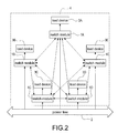
- Fig. 2 shows a block diagram of an application for a preferred embodiment of the present invention.
- Fig. 3 shows a diagram of the switch modules of the present invention and the electric lamps arranged in a room.
- the single switch module 1 of the present invention is used to control and be electrically connected to the single load device 3.
- a group includes a plurality of the switch modules 1.
- a group 4 includes a plurality of the switch modules 1A, 1B, 1C, 1D, and 1E.
- Each of the load devices 3A, 3B, 3C, 3D, and 3E is controlled and electrically connected to the switch modules 1A, 1B, 1C, 1D, and 1E respectively.
- the switch modules 1A, 1B, 1C, 1D, and 1E in the group 4 are electrically connected to each other with the Digital Addressable Lighting Interface (DALI) protocol for addressing. Therefore, the switch modules 1A, 1B, 1C, 1D, and 1E in the group 4 know the addresses of the switch modules 1A, 1B, 1C, 1D, and 1E in the group 4, so that commands and information can be transmitted (through the signal transceiver unit 15) between the switch modules 1A, 1B, 1C, 1D, and 1E in the group 4.
- DALI Digital Addressable Lighting Interface
- the signal transceiver 15 is, for example, a Zigbee transceiver. Commands and information can be transmitted wirelessly from the switch module 1 through the signal transceiver 15 with Zigbee protocol and complying with DALI protocol. Moreover, the signal transceiver 15 can be other kinds of wireless transmission interface, such as Bluetooth or Wi-Fi. Commands and information can be transmitted from the switch module 1 through the power line 2 with DALI or Power Line Communication (PLC) interface. The scope of the present invention is not limited to the examples mentioned above.
- the power statuses of the switch modules 1A, 1B, 1C, 1D, and 1E in the group 4 are detected by the switch modules 1A, 1B, 1C, 1D, and 1E respectively, and then the power status information I1 is generated and transmitted to the main switch module to record in the memory unit 16 when the main switch module is driven to enter a learning mode.
- the power status information I1 recorded in the memory unit 16 includes the power status information I1 of the main switch module.
- the switch modules 1A, 1B, 1C, 1D, and 1E can be controlled by the user respectively to control the action (turn on or off) of the load devices 3A, 3B, 3C, 3D, and 3E respectively. Moreover, the switch modules 1A, 1B, 1C, 1D, and 1E can be controlled by the user respectively to control the percentage of the electricity passing through to control the operation (for example, the brightness of the electric lamp) of the load devices 3A, 3B, 3C, 3D, and 3E respectively if the switch modules 1A, 1B, 1C, 1D, and 1E have fine adjustment function.
- a switch commands S1 (as shown in Fig. 1 ) is sent from the main switch module to the switch modules 1A, 1B, 1C, 1D, and 1E in the group 4 in accordance with the power status information I1 recorded in the memory unit 16 when the main switch module is operated to turn on a backup mode. Therefore, the switch modules 1A, 1B, 1C, 1D, and 1E are switched back to the statuses which are recorded in the learning mode (including on status or off status, and if it is on status, further including the percentage of the electricity passing through). More specifically, the switch command S1 sent from the main switch module to the switch module 1A is in accordance with the power status information I1 sent from the switch module 1A in the learning mode. The switch command S1 sent from the main switch module to the switch module 1B is in accordance with the power status information I1 sent from the switch module 1B in the learning mode, and so on.
- the power statuses of the switch modules 1A, 1B are conducting (i.e. the load devices 3A, 3B are activated), and the power statuses of the switch modules 1C, 1D, 1E are cutting off (i.e. the load devices 3C, 3D, 3E are not activated) when the main switch module enters the learning mode.
- the power status information I1 is recorded in the memory unit 16 by the main switch module.
- the power statuses of the switch modules 1A, 1B will be conducting and the power statuses of the switch modules 1C, 1D, 1E will be cutting off, even if the power statuses of the switch modules 1A, 1B, 1C, 1D, 1E were cutting off (i.e. the load devices 3A, 3B, 3C, 3D, 3E were not activated) before the main switch module is operated to turn on the backup mode.
- the power statuses of the switch modules 1A, 1B, 1C, 1D, 1E in the group 4 are controlled simultaneously by the user with the main switch module. It is very convenient for the user.
- the power statuses of all of the switch modules 1 are cutting off and are recorded in the switch module 1 in the bedroom.
- the power statuses of all of the switch modules 1 will be cut off when the switch module 1 in the bedroom is operated to turn on the backup mode.
- all of the switch modules 1 are cut off easily and the user doesn't need to leave the bedroom to control all of the switch modules 1.
- anyone of the switch modules 1A, 1B, 1C, 1D, 1E in the group 4 can be chosen by the user as a main switch module (i.e. every switch module can be the main switch module, and there may be many main switch modules).
- the power status information I1 of the switch modules 1A, 1B, 1C, 1D, 1E recorded in the switch modules 1A may be different from that recorded in the switch modules 1B, and so on. Therefore, it is convenient and easy for the user to switch the switch modules 1A, 1B, 1C, 1D, 1E respectively in accordance with the power status information I1 recorded in different main switch modules.
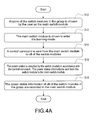
- Fig. 4A shows a flow chart of a preferred embodiment of the present invention.
- anyone of the switch modules 1 in the group 4 is chosen by the user as the main switch module (S10).
- the main switch module is driven to enter the learning mode (S12).
- the user operates the switch unit 11 (for example, the user presses the switch unit 11 three times successively), so that the main switch module is driven to enter the learning mode.
- the method mentioned above is just an example, and the scope of the present invention is not limited to it.
- the power status information I1 sent from all of the switch modules 1 will be received and recorded by the main switch module when the main switch module is driven to enter the learning mode. More specifically, a control command C1 (as shown in Fig. 1 ) is sent from the main switch module to all of the switch modules 1 (S14) when the main switch module is driven to enter the learning mode. Then, the power status (conducting or cutting off, if it is conducting, further including the percentage of the electricity passing through the switch module 1) is detected by the switch module 1 in accordance with the control command C1. The power status information I1 is sent from the switch module 1 to the main switch module (S16). Finally, the power status information I1 of all of the switch modules 1 in the group 4 are recorded in the main switch module (S18).
- the power status information I1 of all of the switch modules 1 in the group 4 are recorded in the main switch module.
- the generating timing of the power status information I1 is the timing when the main switch module is driven to enter the learning mode.
- Fig. 4B shows a flow chart of another preferred embodiment of the present invention.
- the main switch module is operated to turn on a backup mode by the user (S20). More specifically, the user operates the switch unit 11 (for example, the user presses the switch unit 11 five times successively), so that the main switch module is operated to turn on the backup mode.
- the switch unit 11 for example, the user presses the switch unit 11 five times successively
- the main switch module is operated to turn on the backup mode.
- the switch command S1 in accordance with the power status information I1 recorded in the memory unit 16 in the learning mode is sent from the main switch module to all of the switch modules 1 in the group 4 (S22).
- the switch command S1 is received by the switch module 1 through the signal transceiver unit 15.
- the power status of the switch module 1 is switched back to the power status when the main switch module is driven to enter the learning mode (S24).
- Fig. 5 shows a block diagram of another preferred embodiment of the present invention.
- the switch module 1 further includes a display unit 17 electrically connected to the micro control unit 12.
- the display unit 17 is used to display the information of the switch module 1.
- the user will know the power status and the electricity passing through the switch module 1 if the load device 3 (for example, an electric lamp) is electrically connected to the switch module 1.
- the display unit 17 displays the power status (conducting or cutting off, if conducting, further displaying the percentage of the electricity passing through) of the switch module 1 with lights or texts if the load device 3 is not electrically connected to the switch module 1.
- the current consumption of the switch module 1 is detected by the power detecting and controlling unit 13 to generate an amperage information C2.
- the display unit 17 will display the amperage information C2.
- the use of electricity will be calculated by the switch module 1 in accordance with the amperage information C2, and will be displayed on the display unit 17. Therefore, the user will easily know the electricity consumption of the load device 3.
Landscapes
- Engineering & Computer Science (AREA)
- Computer Networks & Wireless Communication (AREA)
- Circuit Arrangement For Electric Light Sources In General (AREA)
Applications Claiming Priority (1)
| Application Number | Priority Date | Filing Date | Title |
|---|---|---|---|
| TW100135849A TWI443502B (zh) | 2011-10-04 | 2011-10-04 | 智慧型開關模組及其操控方法 |
Publications (2)
| Publication Number | Publication Date |
|---|---|
| EP2579691A1 true EP2579691A1 (de) | 2013-04-10 |
| EP2579691B1 EP2579691B1 (de) | 2016-02-10 |
Family
ID=47290587
Family Applications (1)
| Application Number | Title | Priority Date | Filing Date |
|---|---|---|---|
| EP12187221.2A Not-in-force EP2579691B1 (de) | 2011-10-04 | 2012-10-04 | Intelligenter schalter für energieverwaltung und entsprechendes verfahren |
Country Status (3)
| Country | Link |
|---|---|
| US (1) | US20130082527A1 (de) |
| EP (1) | EP2579691B1 (de) |
| TW (1) | TWI443502B (de) |
Cited By (3)
| Publication number | Priority date | Publication date | Assignee | Title |
|---|---|---|---|---|
| WO2018009563A1 (en) * | 2016-07-05 | 2018-01-11 | Lutron Electronics Co., Inc. | State retention load control system |
| CN111132410A (zh) * | 2018-10-28 | 2020-05-08 | 苏州中明光电有限公司 | 一种用于led路灯远距离系统维护的方法 |
| US11437814B2 (en) | 2016-07-05 | 2022-09-06 | Lutron Technology Company Llc | State retention load control system |
Families Citing this family (2)
| Publication number | Priority date | Publication date | Assignee | Title |
|---|---|---|---|---|
| TWI513132B (zh) * | 2013-12-31 | 2015-12-11 | 數位可定址調整照明方法與系統 | |
| US9848480B1 (en) | 2016-06-14 | 2017-12-19 | Honeywell International Inc. | Lightbulb in a fixture having a configuration memory |
Citations (4)
| Publication number | Priority date | Publication date | Assignee | Title |
|---|---|---|---|---|
| EP1450383A1 (de) * | 2003-01-07 | 2004-08-25 | Taiwan Fuhbic Corporation | Intelligentes Schaltgerät und Steuerungssystem |
| US20090302782A1 (en) * | 2008-06-10 | 2009-12-10 | Tesla Controls Corporation | Systems and methods for rules based, automated lighting control |
| US20100077404A1 (en) * | 2008-09-25 | 2010-03-25 | Hyun-Woo Oh | System and method of controlling sensory devices |
| WO2010116283A2 (en) * | 2009-04-09 | 2010-10-14 | Koninklijke Philips Electronics N.V. | Intelligent lighting control system |
Family Cites Families (5)
| Publication number | Priority date | Publication date | Assignee | Title |
|---|---|---|---|---|
| US5479155A (en) * | 1988-12-05 | 1995-12-26 | Prince Corporation | Vehicle accessory trainable transmitter |
| US20080094857A1 (en) * | 2006-10-20 | 2008-04-24 | Smith Robert B | LED light bulb |
| CN102314167A (zh) * | 2010-07-05 | 2012-01-11 | 德尔菲技术公司 | 中央电气盒、电子电气系统和包含该电子电气系统的车辆 |
| US8364326B2 (en) * | 2011-02-22 | 2013-01-29 | Asoka Usa Corporation | Set of sensor units for communication enabled for streaming media delivery with monitoring and control of power usage of connected appliances |
| US8587453B2 (en) * | 2011-04-13 | 2013-11-19 | Jeffrey L. Cripps | Portable traffic signaling system |
-
2011
- 2011-10-04 TW TW100135849A patent/TWI443502B/zh not_active IP Right Cessation
-
2012
- 2012-10-04 US US13/644,512 patent/US20130082527A1/en not_active Abandoned
- 2012-10-04 EP EP12187221.2A patent/EP2579691B1/de not_active Not-in-force
Patent Citations (4)
| Publication number | Priority date | Publication date | Assignee | Title |
|---|---|---|---|---|
| EP1450383A1 (de) * | 2003-01-07 | 2004-08-25 | Taiwan Fuhbic Corporation | Intelligentes Schaltgerät und Steuerungssystem |
| US20090302782A1 (en) * | 2008-06-10 | 2009-12-10 | Tesla Controls Corporation | Systems and methods for rules based, automated lighting control |
| US20100077404A1 (en) * | 2008-09-25 | 2010-03-25 | Hyun-Woo Oh | System and method of controlling sensory devices |
| WO2010116283A2 (en) * | 2009-04-09 | 2010-10-14 | Koninklijke Philips Electronics N.V. | Intelligent lighting control system |
Cited By (11)
| Publication number | Priority date | Publication date | Assignee | Title |
|---|---|---|---|---|
| WO2018009563A1 (en) * | 2016-07-05 | 2018-01-11 | Lutron Electronics Co., Inc. | State retention load control system |
| CN109644149A (zh) * | 2016-07-05 | 2019-04-16 | 卢特龙电子公司 | 状态保持负载控制系统 |
| US10772180B2 (en) | 2016-07-05 | 2020-09-08 | Lutron Technology Company Llc | State retention load control system |
| US11196581B2 (en) | 2016-07-05 | 2021-12-07 | Lutron Technology Company Llc | State retention load control system |
| US11437814B2 (en) | 2016-07-05 | 2022-09-06 | Lutron Technology Company Llc | State retention load control system |
| US11658840B2 (en) | 2016-07-05 | 2023-05-23 | Lutron Technology Company Llc | State retention load control system |
| US11832368B2 (en) | 2016-07-05 | 2023-11-28 | Lutron Technology Company Llc | State retention load control system |
| US11924000B2 (en) | 2016-07-05 | 2024-03-05 | Lutron Technology Company Llc | State retention load control system |
| US12295084B2 (en) | 2016-07-05 | 2025-05-06 | Lutron Technology Company Llc | State retention load control system |
| US12418436B2 (en) | 2016-07-05 | 2025-09-16 | Lutron Technology Company Llc | State retention load control system |
| CN111132410A (zh) * | 2018-10-28 | 2020-05-08 | 苏州中明光电有限公司 | 一种用于led路灯远距离系统维护的方法 |
Also Published As
| Publication number | Publication date |
|---|---|
| EP2579691B1 (de) | 2016-02-10 |
| US20130082527A1 (en) | 2013-04-04 |
| TWI443502B (zh) | 2014-07-01 |
| TW201316160A (zh) | 2013-04-16 |
Similar Documents
| Publication | Publication Date | Title |
|---|---|---|
| US20210048910A1 (en) | Modular touch panel smart switches and systems | |
| US10638585B2 (en) | Associating wireless control devices | |
| JP4932849B2 (ja) | 電源制御可能なコンセント装置 | |
| EP2582210A1 (de) | Intelligentes Stromsteuerungssystem | |
| CN105593959A (zh) | 容易安装的家庭自动化灯开关 | |
| US20130082527A1 (en) | Intellectual switch module and operating method for the same | |
| CN111491422B (zh) | 负载控制系统,系统控制器和关联装置 | |
| CN106102261A (zh) | 遥控灯具方法 | |
| US10915241B2 (en) | Communication device with ID input method which conforms to positional notation of numeral system | |
| CN105023419A (zh) | 一种手机蓝牙控制开关及控制方法 | |
| JP2011523494A (ja) | 局所的な照明装置の制御を含む、エリア・ベースの照明制御システム | |
| US20190274199A1 (en) | Switching device with auxiliary power unit and wireless receiver function, and lamp system using the same | |
| CN113438564B (zh) | 控制系统、终端的处理方法、无线开关及其处理方法 | |
| CN103048957B (zh) | 智能型电源控制系统 | |
| CN203675391U (zh) | 一种智能调光的led照明系统 | |
| CN202794902U (zh) | 一种智能开关系统 | |
| CN205545307U (zh) | 一种poe控制器及poe控制系统 | |
| US20140049107A1 (en) | Intelligent Lighting and Electrical System | |
| US20130223302A1 (en) | Multi-protocol switching control system suitable for controlling different electronic devices of different protocols | |
| CN103049986B (zh) | 智能型开关模块及其操控方法 | |
| CN211557600U (zh) | 双控开关和双控控制系统 | |
| KR20090006140U (ko) | 무선제어 멀티탭과 상태 모니터링 시스템 | |
| US9818278B2 (en) | Intelligent household controller | |
| CN203151609U (zh) | 一种手机蓝牙控制开关 | |
| CN105530103A (zh) | 一种poe控制器及poe控制系统 |
Legal Events
| Date | Code | Title | Description |
|---|---|---|---|
| PUAI | Public reference made under article 153(3) epc to a published international application that has entered the european phase |
Free format text: ORIGINAL CODE: 0009012 |
|
| AK | Designated contracting states |
Kind code of ref document: A1 Designated state(s): AL AT BE BG CH CY CZ DE DK EE ES FI FR GB GR HR HU IE IS IT LI LT LU LV MC MK MT NL NO PL PT RO RS SE SI SK SM TR |
|
| AX | Request for extension of the european patent |
Extension state: BA ME |
|
| 17P | Request for examination filed |
Effective date: 20130506 |
|
| 17Q | First examination report despatched |
Effective date: 20140709 |
|
| GRAP | Despatch of communication of intention to grant a patent |
Free format text: ORIGINAL CODE: EPIDOSNIGR1 |
|
| INTG | Intention to grant announced |
Effective date: 20150701 |
|
| RIN1 | Information on inventor provided before grant (corrected) |
Inventor name: SHER, SHANG-FANG Inventor name: LIAO, CHUN-KAI |
|
| GRAS | Grant fee paid |
Free format text: ORIGINAL CODE: EPIDOSNIGR3 |
|
| GRAA | (expected) grant |
Free format text: ORIGINAL CODE: 0009210 |
|
| INTG | Intention to grant announced |
Effective date: 20151204 |
|
| AK | Designated contracting states |
Kind code of ref document: B1 Designated state(s): AL AT BE BG CH CY CZ DE DK EE ES FI FR GB GR HR HU IE IS IT LI LT LU LV MC MK MT NL NO PL PT RO RS SE SI SK SM TR |
|
| REG | Reference to a national code |
Ref country code: GB Ref legal event code: FG4D |
|
| REG | Reference to a national code |
Ref country code: AT Ref legal event code: REF Ref document number: 775192 Country of ref document: AT Kind code of ref document: T Effective date: 20160215 Ref country code: CH Ref legal event code: EP |
|
| REG | Reference to a national code |
Ref country code: IE Ref legal event code: FG4D |
|
| REG | Reference to a national code |
Ref country code: DE Ref legal event code: R096 Ref document number: 602012014637 Country of ref document: DE |
|
| REG | Reference to a national code |
Ref country code: NL Ref legal event code: FP |
|
| REG | Reference to a national code |
Ref country code: LT Ref legal event code: MG4D |
|
| REG | Reference to a national code |
Ref country code: AT Ref legal event code: MK05 Ref document number: 775192 Country of ref document: AT Kind code of ref document: T Effective date: 20160210 |
|
| PG25 | Lapsed in a contracting state [announced via postgrant information from national office to epo] |
Ref country code: ES Free format text: LAPSE BECAUSE OF FAILURE TO SUBMIT A TRANSLATION OF THE DESCRIPTION OR TO PAY THE FEE WITHIN THE PRESCRIBED TIME-LIMIT Effective date: 20160210 Ref country code: IT Free format text: LAPSE BECAUSE OF FAILURE TO SUBMIT A TRANSLATION OF THE DESCRIPTION OR TO PAY THE FEE WITHIN THE PRESCRIBED TIME-LIMIT Effective date: 20160210 Ref country code: NO Free format text: LAPSE BECAUSE OF FAILURE TO SUBMIT A TRANSLATION OF THE DESCRIPTION OR TO PAY THE FEE WITHIN THE PRESCRIBED TIME-LIMIT Effective date: 20160510 Ref country code: FI Free format text: LAPSE BECAUSE OF FAILURE TO SUBMIT A TRANSLATION OF THE DESCRIPTION OR TO PAY THE FEE WITHIN THE PRESCRIBED TIME-LIMIT Effective date: 20160210 Ref country code: HR Free format text: LAPSE BECAUSE OF FAILURE TO SUBMIT A TRANSLATION OF THE DESCRIPTION OR TO PAY THE FEE WITHIN THE PRESCRIBED TIME-LIMIT Effective date: 20160210 |
|
| PG25 | Lapsed in a contracting state [announced via postgrant information from national office to epo] |
Ref country code: LT Free format text: LAPSE BECAUSE OF FAILURE TO SUBMIT A TRANSLATION OF THE DESCRIPTION OR TO PAY THE FEE WITHIN THE PRESCRIBED TIME-LIMIT Effective date: 20160210 Ref country code: AT Free format text: LAPSE BECAUSE OF FAILURE TO SUBMIT A TRANSLATION OF THE DESCRIPTION OR TO PAY THE FEE WITHIN THE PRESCRIBED TIME-LIMIT Effective date: 20160210 Ref country code: SE Free format text: LAPSE BECAUSE OF FAILURE TO SUBMIT A TRANSLATION OF THE DESCRIPTION OR TO PAY THE FEE WITHIN THE PRESCRIBED TIME-LIMIT Effective date: 20160210 Ref country code: PL Free format text: LAPSE BECAUSE OF FAILURE TO SUBMIT A TRANSLATION OF THE DESCRIPTION OR TO PAY THE FEE WITHIN THE PRESCRIBED TIME-LIMIT Effective date: 20160210 Ref country code: IS Free format text: LAPSE BECAUSE OF FAILURE TO SUBMIT A TRANSLATION OF THE DESCRIPTION OR TO PAY THE FEE WITHIN THE PRESCRIBED TIME-LIMIT Effective date: 20160610 Ref country code: RS Free format text: LAPSE BECAUSE OF FAILURE TO SUBMIT A TRANSLATION OF THE DESCRIPTION OR TO PAY THE FEE WITHIN THE PRESCRIBED TIME-LIMIT Effective date: 20160210 Ref country code: PT Free format text: LAPSE BECAUSE OF FAILURE TO SUBMIT A TRANSLATION OF THE DESCRIPTION OR TO PAY THE FEE WITHIN THE PRESCRIBED TIME-LIMIT Effective date: 20160613 Ref country code: LV Free format text: LAPSE BECAUSE OF FAILURE TO SUBMIT A TRANSLATION OF THE DESCRIPTION OR TO PAY THE FEE WITHIN THE PRESCRIBED TIME-LIMIT Effective date: 20160210 |
|
| REG | Reference to a national code |
Ref country code: FR Ref legal event code: PLFP Year of fee payment: 5 |
|
| PG25 | Lapsed in a contracting state [announced via postgrant information from national office to epo] |
Ref country code: EE Free format text: LAPSE BECAUSE OF FAILURE TO SUBMIT A TRANSLATION OF THE DESCRIPTION OR TO PAY THE FEE WITHIN THE PRESCRIBED TIME-LIMIT Effective date: 20160210 Ref country code: DK Free format text: LAPSE BECAUSE OF FAILURE TO SUBMIT A TRANSLATION OF THE DESCRIPTION OR TO PAY THE FEE WITHIN THE PRESCRIBED TIME-LIMIT Effective date: 20160210 |
|
| REG | Reference to a national code |
Ref country code: DE Ref legal event code: R097 Ref document number: 602012014637 Country of ref document: DE |
|
| PG25 | Lapsed in a contracting state [announced via postgrant information from national office to epo] |
Ref country code: SK Free format text: LAPSE BECAUSE OF FAILURE TO SUBMIT A TRANSLATION OF THE DESCRIPTION OR TO PAY THE FEE WITHIN THE PRESCRIBED TIME-LIMIT Effective date: 20160210 Ref country code: SM Free format text: LAPSE BECAUSE OF FAILURE TO SUBMIT A TRANSLATION OF THE DESCRIPTION OR TO PAY THE FEE WITHIN THE PRESCRIBED TIME-LIMIT Effective date: 20160210 Ref country code: RO Free format text: LAPSE BECAUSE OF FAILURE TO SUBMIT A TRANSLATION OF THE DESCRIPTION OR TO PAY THE FEE WITHIN THE PRESCRIBED TIME-LIMIT Effective date: 20160210 Ref country code: CZ Free format text: LAPSE BECAUSE OF FAILURE TO SUBMIT A TRANSLATION OF THE DESCRIPTION OR TO PAY THE FEE WITHIN THE PRESCRIBED TIME-LIMIT Effective date: 20160210 |
|
| PGFP | Annual fee paid to national office [announced via postgrant information from national office to epo] |
Ref country code: FR Payment date: 20160929 Year of fee payment: 5 |
|
| PLBE | No opposition filed within time limit |
Free format text: ORIGINAL CODE: 0009261 |
|
| STAA | Information on the status of an ep patent application or granted ep patent |
Free format text: STATUS: NO OPPOSITION FILED WITHIN TIME LIMIT |
|
| PG25 | Lapsed in a contracting state [announced via postgrant information from national office to epo] |
Ref country code: BE Free format text: LAPSE BECAUSE OF FAILURE TO SUBMIT A TRANSLATION OF THE DESCRIPTION OR TO PAY THE FEE WITHIN THE PRESCRIBED TIME-LIMIT Effective date: 20160210 |
|
| 26N | No opposition filed |
Effective date: 20161111 |
|
| PGFP | Annual fee paid to national office [announced via postgrant information from national office to epo] |
Ref country code: NL Payment date: 20161019 Year of fee payment: 5 Ref country code: GB Payment date: 20161025 Year of fee payment: 5 Ref country code: DE Payment date: 20161028 Year of fee payment: 5 |
|
| PG25 | Lapsed in a contracting state [announced via postgrant information from national office to epo] |
Ref country code: SI Free format text: LAPSE BECAUSE OF FAILURE TO SUBMIT A TRANSLATION OF THE DESCRIPTION OR TO PAY THE FEE WITHIN THE PRESCRIBED TIME-LIMIT Effective date: 20160210 Ref country code: BG Free format text: LAPSE BECAUSE OF FAILURE TO SUBMIT A TRANSLATION OF THE DESCRIPTION OR TO PAY THE FEE WITHIN THE PRESCRIBED TIME-LIMIT Effective date: 20160510 |
|
| REG | Reference to a national code |
Ref country code: CH Ref legal event code: PL |
|
| REG | Reference to a national code |
Ref country code: IE Ref legal event code: MM4A |
|
| PG25 | Lapsed in a contracting state [announced via postgrant information from national office to epo] |
Ref country code: LI Free format text: LAPSE BECAUSE OF NON-PAYMENT OF DUE FEES Effective date: 20161031 Ref country code: CH Free format text: LAPSE BECAUSE OF NON-PAYMENT OF DUE FEES Effective date: 20161031 |
|
| PG25 | Lapsed in a contracting state [announced via postgrant information from national office to epo] |
Ref country code: LU Free format text: LAPSE BECAUSE OF NON-PAYMENT OF DUE FEES Effective date: 20161004 |
|
| PG25 | Lapsed in a contracting state [announced via postgrant information from national office to epo] |
Ref country code: IE Free format text: LAPSE BECAUSE OF NON-PAYMENT OF DUE FEES Effective date: 20161004 |
|
| REG | Reference to a national code |
Ref country code: DE Ref legal event code: R119 Ref document number: 602012014637 Country of ref document: DE |
|
| PG25 | Lapsed in a contracting state [announced via postgrant information from national office to epo] |
Ref country code: CY Free format text: LAPSE BECAUSE OF FAILURE TO SUBMIT A TRANSLATION OF THE DESCRIPTION OR TO PAY THE FEE WITHIN THE PRESCRIBED TIME-LIMIT Effective date: 20160210 Ref country code: HU Free format text: LAPSE BECAUSE OF FAILURE TO SUBMIT A TRANSLATION OF THE DESCRIPTION OR TO PAY THE FEE WITHIN THE PRESCRIBED TIME-LIMIT; INVALID AB INITIO Effective date: 20121004 |
|
| REG | Reference to a national code |
Ref country code: NL Ref legal event code: MM Effective date: 20171101 |
|
| GBPC | Gb: european patent ceased through non-payment of renewal fee |
Effective date: 20171004 |
|
| PG25 | Lapsed in a contracting state [announced via postgrant information from national office to epo] |
Ref country code: GR Free format text: LAPSE BECAUSE OF FAILURE TO SUBMIT A TRANSLATION OF THE DESCRIPTION OR TO PAY THE FEE WITHIN THE PRESCRIBED TIME-LIMIT Effective date: 20160210 Ref country code: MC Free format text: LAPSE BECAUSE OF FAILURE TO SUBMIT A TRANSLATION OF THE DESCRIPTION OR TO PAY THE FEE WITHIN THE PRESCRIBED TIME-LIMIT Effective date: 20160210 Ref country code: TR Free format text: LAPSE BECAUSE OF FAILURE TO SUBMIT A TRANSLATION OF THE DESCRIPTION OR TO PAY THE FEE WITHIN THE PRESCRIBED TIME-LIMIT Effective date: 20160210 Ref country code: MK Free format text: LAPSE BECAUSE OF FAILURE TO SUBMIT A TRANSLATION OF THE DESCRIPTION OR TO PAY THE FEE WITHIN THE PRESCRIBED TIME-LIMIT Effective date: 20160210 Ref country code: MT Free format text: LAPSE BECAUSE OF NON-PAYMENT OF DUE FEES Effective date: 20161031 |
|
| REG | Reference to a national code |
Ref country code: FR Ref legal event code: ST Effective date: 20180629 |
|
| PG25 | Lapsed in a contracting state [announced via postgrant information from national office to epo] |
Ref country code: NL Free format text: LAPSE BECAUSE OF NON-PAYMENT OF DUE FEES Effective date: 20171101 Ref country code: DE Free format text: LAPSE BECAUSE OF NON-PAYMENT OF DUE FEES Effective date: 20180501 Ref country code: GB Free format text: LAPSE BECAUSE OF NON-PAYMENT OF DUE FEES Effective date: 20171004 |
|
| PG25 | Lapsed in a contracting state [announced via postgrant information from national office to epo] |
Ref country code: FR Free format text: LAPSE BECAUSE OF NON-PAYMENT OF DUE FEES Effective date: 20171031 |
|
| PG25 | Lapsed in a contracting state [announced via postgrant information from national office to epo] |
Ref country code: AL Free format text: LAPSE BECAUSE OF FAILURE TO SUBMIT A TRANSLATION OF THE DESCRIPTION OR TO PAY THE FEE WITHIN THE PRESCRIBED TIME-LIMIT Effective date: 20160210 |