EP2580080B1 - Hydraulische anlage - Google Patents
Hydraulische anlage Download PDFInfo
- Publication number
- EP2580080B1 EP2580080B1 EP11722019.4A EP11722019A EP2580080B1 EP 2580080 B1 EP2580080 B1 EP 2580080B1 EP 11722019 A EP11722019 A EP 11722019A EP 2580080 B1 EP2580080 B1 EP 2580080B1
- Authority
- EP
- European Patent Office
- Prior art keywords
- pressure
- pressure fluid
- fluid chamber
- pressurising medium
- low
- Prior art date
- Legal status (The legal status is an assumption and is not a legal conclusion. Google has not performed a legal analysis and makes no representation as to the accuracy of the status listed.)
- Not-in-force
Links
- 239000012530 fluid Substances 0.000 claims description 52
- 238000010276 construction Methods 0.000 claims description 7
- 239000007789 gas Substances 0.000 description 9
- MWUXSHHQAYIFBG-UHFFFAOYSA-N nitrogen oxide Inorganic materials O=[N] MWUXSHHQAYIFBG-UHFFFAOYSA-N 0.000 description 6
- IJGRMHOSHXDMSA-UHFFFAOYSA-N Atomic nitrogen Chemical compound N#N IJGRMHOSHXDMSA-UHFFFAOYSA-N 0.000 description 5
- 238000002485 combustion reaction Methods 0.000 description 5
- 230000009467 reduction Effects 0.000 description 5
- 238000005192 partition Methods 0.000 description 4
- 238000001816 cooling Methods 0.000 description 3
- 230000008878 coupling Effects 0.000 description 3
- 238000010168 coupling process Methods 0.000 description 3
- 238000005859 coupling reaction Methods 0.000 description 3
- 239000003921 oil Substances 0.000 description 3
- 230000002441 reversible effect Effects 0.000 description 3
- 238000010586 diagram Methods 0.000 description 2
- 238000006073 displacement reaction Methods 0.000 description 2
- 238000009434 installation Methods 0.000 description 2
- 229910052757 nitrogen Inorganic materials 0.000 description 2
- XSQUKJJJFZCRTK-UHFFFAOYSA-N Urea Chemical compound NC(N)=O XSQUKJJJFZCRTK-UHFFFAOYSA-N 0.000 description 1
- 239000004202 carbamide Substances 0.000 description 1
- 239000003054 catalyst Substances 0.000 description 1
- 230000007423 decrease Effects 0.000 description 1
- 230000009977 dual effect Effects 0.000 description 1
- 230000000694 effects Effects 0.000 description 1
- 238000004146 energy storage Methods 0.000 description 1
- 239000010720 hydraulic oil Substances 0.000 description 1
- 230000002706 hydrostatic effect Effects 0.000 description 1
- 230000004941 influx Effects 0.000 description 1
- 238000005457 optimization Methods 0.000 description 1
- 239000002245 particle Substances 0.000 description 1
- 230000036316 preload Effects 0.000 description 1
- 230000004044 response Effects 0.000 description 1
- 238000007789 sealing Methods 0.000 description 1
- 230000008054 signal transmission Effects 0.000 description 1
- 238000011144 upstream manufacturing Methods 0.000 description 1
Images
Classifications
-
- F—MECHANICAL ENGINEERING; LIGHTING; HEATING; WEAPONS; BLASTING
- F15—FLUID-PRESSURE ACTUATORS; HYDRAULICS OR PNEUMATICS IN GENERAL
- F15B—SYSTEMS ACTING BY MEANS OF FLUIDS IN GENERAL; FLUID-PRESSURE ACTUATORS, e.g. SERVOMOTORS; DETAILS OF FLUID-PRESSURE SYSTEMS, NOT OTHERWISE PROVIDED FOR
- F15B1/00—Installations or systems with accumulators; Supply reservoir or sump assemblies
- F15B1/02—Installations or systems with accumulators
- F15B1/024—Installations or systems with accumulators used as a supplementary power source, e.g. to store energy in idle periods to balance pump load
-
- E—FIXED CONSTRUCTIONS
- E02—HYDRAULIC ENGINEERING; FOUNDATIONS; SOIL SHIFTING
- E02F—DREDGING; SOIL-SHIFTING
- E02F9/00—Component parts of dredgers or soil-shifting machines, not restricted to one of the kinds covered by groups E02F3/00 - E02F7/00
- E02F9/20—Drives; Control devices
- E02F9/22—Hydraulic or pneumatic drives
- E02F9/2217—Hydraulic or pneumatic drives with energy recovery arrangements, e.g. using accumulators, flywheels
-
- E—FIXED CONSTRUCTIONS
- E02—HYDRAULIC ENGINEERING; FOUNDATIONS; SOIL SHIFTING
- E02F—DREDGING; SOIL-SHIFTING
- E02F9/00—Component parts of dredgers or soil-shifting machines, not restricted to one of the kinds covered by groups E02F3/00 - E02F7/00
- E02F9/20—Drives; Control devices
- E02F9/22—Hydraulic or pneumatic drives
- E02F9/2278—Hydraulic circuits
- E02F9/2289—Closed circuit
-
- E—FIXED CONSTRUCTIONS
- E02—HYDRAULIC ENGINEERING; FOUNDATIONS; SOIL SHIFTING
- E02F—DREDGING; SOIL-SHIFTING
- E02F9/00—Component parts of dredgers or soil-shifting machines, not restricted to one of the kinds covered by groups E02F3/00 - E02F7/00
- E02F9/20—Drives; Control devices
- E02F9/22—Hydraulic or pneumatic drives
- E02F9/2278—Hydraulic circuits
- E02F9/2296—Systems with a variable displacement pump
-
- F—MECHANICAL ENGINEERING; LIGHTING; HEATING; WEAPONS; BLASTING
- F15—FLUID-PRESSURE ACTUATORS; HYDRAULICS OR PNEUMATICS IN GENERAL
- F15B—SYSTEMS ACTING BY MEANS OF FLUIDS IN GENERAL; FLUID-PRESSURE ACTUATORS, e.g. SERVOMOTORS; DETAILS OF FLUID-PRESSURE SYSTEMS, NOT OTHERWISE PROVIDED FOR
- F15B21/00—Common features of fluid actuator systems; Fluid-pressure actuator systems or details thereof, not covered by any other group of this subclass
- F15B21/04—Special measures taken in connection with the properties of the fluid
- F15B21/047—Preventing foaming, churning or cavitation
-
- F—MECHANICAL ENGINEERING; LIGHTING; HEATING; WEAPONS; BLASTING
- F15—FLUID-PRESSURE ACTUATORS; HYDRAULICS OR PNEUMATICS IN GENERAL
- F15B—SYSTEMS ACTING BY MEANS OF FLUIDS IN GENERAL; FLUID-PRESSURE ACTUATORS, e.g. SERVOMOTORS; DETAILS OF FLUID-PRESSURE SYSTEMS, NOT OTHERWISE PROVIDED FOR
- F15B1/00—Installations or systems with accumulators; Supply reservoir or sump assemblies
- F15B1/02—Installations or systems with accumulators
- F15B1/04—Accumulators
- F15B1/08—Accumulators using a gas cushion; Gas charging devices; Indicators or floats therefor
- F15B1/24—Accumulators using a gas cushion; Gas charging devices; Indicators or floats therefor with rigid separating means, e.g. pistons
-
- F—MECHANICAL ENGINEERING; LIGHTING; HEATING; WEAPONS; BLASTING
- F15—FLUID-PRESSURE ACTUATORS; HYDRAULICS OR PNEUMATICS IN GENERAL
- F15B—SYSTEMS ACTING BY MEANS OF FLUIDS IN GENERAL; FLUID-PRESSURE ACTUATORS, e.g. SERVOMOTORS; DETAILS OF FLUID-PRESSURE SYSTEMS, NOT OTHERWISE PROVIDED FOR
- F15B2201/00—Accumulators
- F15B2201/20—Accumulator cushioning means
- F15B2201/205—Accumulator cushioning means using gas
-
- F—MECHANICAL ENGINEERING; LIGHTING; HEATING; WEAPONS; BLASTING
- F15—FLUID-PRESSURE ACTUATORS; HYDRAULICS OR PNEUMATICS IN GENERAL
- F15B—SYSTEMS ACTING BY MEANS OF FLUIDS IN GENERAL; FLUID-PRESSURE ACTUATORS, e.g. SERVOMOTORS; DETAILS OF FLUID-PRESSURE SYSTEMS, NOT OTHERWISE PROVIDED FOR
- F15B2201/00—Accumulators
- F15B2201/30—Accumulator separating means
- F15B2201/31—Accumulator separating means having rigid separating means, e.g. pistons
-
- F—MECHANICAL ENGINEERING; LIGHTING; HEATING; WEAPONS; BLASTING
- F15—FLUID-PRESSURE ACTUATORS; HYDRAULICS OR PNEUMATICS IN GENERAL
- F15B—SYSTEMS ACTING BY MEANS OF FLUIDS IN GENERAL; FLUID-PRESSURE ACTUATORS, e.g. SERVOMOTORS; DETAILS OF FLUID-PRESSURE SYSTEMS, NOT OTHERWISE PROVIDED FOR
- F15B2201/00—Accumulators
- F15B2201/30—Accumulator separating means
- F15B2201/32—Accumulator separating means having multiple separating means, e.g. with an auxiliary piston sliding within a main piston, multiple membranes or combinations thereof
-
- F—MECHANICAL ENGINEERING; LIGHTING; HEATING; WEAPONS; BLASTING
- F15—FLUID-PRESSURE ACTUATORS; HYDRAULICS OR PNEUMATICS IN GENERAL
- F15B—SYSTEMS ACTING BY MEANS OF FLUIDS IN GENERAL; FLUID-PRESSURE ACTUATORS, e.g. SERVOMOTORS; DETAILS OF FLUID-PRESSURE SYSTEMS, NOT OTHERWISE PROVIDED FOR
- F15B2201/00—Accumulators
- F15B2201/40—Constructional details of accumulators not otherwise provided for
- F15B2201/415—Gas ports
-
- F—MECHANICAL ENGINEERING; LIGHTING; HEATING; WEAPONS; BLASTING
- F15—FLUID-PRESSURE ACTUATORS; HYDRAULICS OR PNEUMATICS IN GENERAL
- F15B—SYSTEMS ACTING BY MEANS OF FLUIDS IN GENERAL; FLUID-PRESSURE ACTUATORS, e.g. SERVOMOTORS; DETAILS OF FLUID-PRESSURE SYSTEMS, NOT OTHERWISE PROVIDED FOR
- F15B2211/00—Circuits for servomotor systems
- F15B2211/20—Fluid pressure source, e.g. accumulator or variable axial piston pump
- F15B2211/205—Systems with pumps
- F15B2211/2053—Type of pump
- F15B2211/20546—Type of pump variable capacity
-
- F—MECHANICAL ENGINEERING; LIGHTING; HEATING; WEAPONS; BLASTING
- F15—FLUID-PRESSURE ACTUATORS; HYDRAULICS OR PNEUMATICS IN GENERAL
- F15B—SYSTEMS ACTING BY MEANS OF FLUIDS IN GENERAL; FLUID-PRESSURE ACTUATORS, e.g. SERVOMOTORS; DETAILS OF FLUID-PRESSURE SYSTEMS, NOT OTHERWISE PROVIDED FOR
- F15B2211/00—Circuits for servomotor systems
- F15B2211/20—Fluid pressure source, e.g. accumulator or variable axial piston pump
- F15B2211/205—Systems with pumps
- F15B2211/2053—Type of pump
- F15B2211/20561—Type of pump reversible
-
- F—MECHANICAL ENGINEERING; LIGHTING; HEATING; WEAPONS; BLASTING
- F15—FLUID-PRESSURE ACTUATORS; HYDRAULICS OR PNEUMATICS IN GENERAL
- F15B—SYSTEMS ACTING BY MEANS OF FLUIDS IN GENERAL; FLUID-PRESSURE ACTUATORS, e.g. SERVOMOTORS; DETAILS OF FLUID-PRESSURE SYSTEMS, NOT OTHERWISE PROVIDED FOR
- F15B2211/00—Circuits for servomotor systems
- F15B2211/20—Fluid pressure source, e.g. accumulator or variable axial piston pump
- F15B2211/21—Systems with pressure sources other than pumps, e.g. with a pyrotechnical charge
- F15B2211/212—Systems with pressure sources other than pumps, e.g. with a pyrotechnical charge the pressure sources being accumulators
-
- F—MECHANICAL ENGINEERING; LIGHTING; HEATING; WEAPONS; BLASTING
- F15—FLUID-PRESSURE ACTUATORS; HYDRAULICS OR PNEUMATICS IN GENERAL
- F15B—SYSTEMS ACTING BY MEANS OF FLUIDS IN GENERAL; FLUID-PRESSURE ACTUATORS, e.g. SERVOMOTORS; DETAILS OF FLUID-PRESSURE SYSTEMS, NOT OTHERWISE PROVIDED FOR
- F15B2211/00—Circuits for servomotor systems
- F15B2211/60—Circuit components or control therefor
- F15B2211/61—Secondary circuits
- F15B2211/613—Feeding circuits
-
- F—MECHANICAL ENGINEERING; LIGHTING; HEATING; WEAPONS; BLASTING
- F15—FLUID-PRESSURE ACTUATORS; HYDRAULICS OR PNEUMATICS IN GENERAL
- F15B—SYSTEMS ACTING BY MEANS OF FLUIDS IN GENERAL; FLUID-PRESSURE ACTUATORS, e.g. SERVOMOTORS; DETAILS OF FLUID-PRESSURE SYSTEMS, NOT OTHERWISE PROVIDED FOR
- F15B2211/00—Circuits for servomotor systems
- F15B2211/80—Other types of control related to particular problems or conditions
- F15B2211/86—Control during or prevention of abnormal conditions
- F15B2211/8609—Control during or prevention of abnormal conditions the abnormal condition being cavitation
Definitions
- the invention relates to a hydraulic system, in particular for a commercial vehicle, such as a construction machine, with a reversible in the conveying direction and variably adjustable in the delivery pressure medium pump, wherein the pressure medium pump takes the pressure fluid via a first fluid-conducting connection of a low-pressure fluid chamber of a double piston accumulator and in a High-pressure fluid space of the double-piston accumulator promotes, which is arranged between the pressure medium pump and the consumer and that the volume of the low-pressure fluid space is greater than the volume of the high-pressure fluid chamber.
- Hydraulic equipment for commercial vehicles are generally composed of multiple hydrostatic drive systems.
- these include the cooling, control and feeding hydraulics as well as the driving hydraulics.
- these systems can work partially independently of each other and fulfill their respective function.
- the steering system In moving construction machines, the steering system is regularly operated with a steering valve with so-called "open center", wherein a constant pump often formed as external gear pump promotes non-actuated steering system against the pressure fluid tank of the construction machine.
- a vane pump with adjustable displacement For passenger cars takes over the promotion of pressure medium within an open system thus formed usually a vane pump with adjustable displacement.
- a so-called open hydraulic circuit for example, the functions cooling, control and supply circuit can be covered with only one pressure medium pump. It may be an external gear pump with a constant displacement volume, which is attached to a power take-off of the internal combustion engine as a motor unit.
- a cooling motor formed, for example, as districtenzahnradkonstantmotor a parallel connection of control and feed hydraulic circuit can be provided.
- the control pressure system is used for signal transmission of certain machine characteristics, such as the control of a disk parking brake or a Schwenkwinkelverstell Road the drive pump by means of trigger valve.
- certain machine characteristics such as the control of a disk parking brake or a Schwenkwinkelverstell
- trigger valve By the use of the feed system, both the supply of fresh, purified hydraulic oil and an internal leakage compensation takes place.
- a hydraulic energy storage system in which a motor-pump unit is arranged between a high-pressure accumulator and a low-pressure accumulator.
- valves are provided in the piston of the low-pressure accumulator, which allow depending on the actuation of the piston feeding the hydraulic fluid into the low-pressure fluid chamber and thus the hydraulic circuit.
- it is also known to compensate for the power peaks of the motor unit, in particular in the form of an internal combustion engine, by the use of a pressure medium accumulator, wherein the accumulator is charged or discharged in response to a current power output of the motor unit.
- the total power of the motor unit in the sense of downsizing can be limited to a predefinable value, for example to the legally prescribed motor power class up to 56kW.
- the pressure medium supply to the consumers and to a pressure fluid reservoir of the hydraulic system is often controlled by a so-called priority valve.
- a connection and disconnection of the pressure medium supply to one or more consumers is controlled by a further valve.
- the invention is therefore based on the object to provide a hydraulic system for a commercial vehicle, which on the one hand allows a reduction in performance for the internal combustion engine and on the other hand, the problem of cavitation is solved.
- the pressure medium pressure in the low-pressure fluid chamber is chosen such that it is sufficient to actuate a pilot control device for the pressure medium pump.
- the pilot control device may be a hydraulic device provided with one or more adjusting cylinders, for example to determine the pivoting angle of a cam ring of a vane pump or the like, and thus to specify the flow rate and conveying direction of the pressure medium pump.
- the suction side of the pressure medium pump a pressure medium is removed from a low-pressure fluid chamber of the hydraulic system and conveyed into a high-pressure fluid chamber of the hydraulic system, a constructive measure is taken, always biased by the pressure fluid pump pressure medium slightly or such that the Cavitation in the hydraulic system is avoided.
- the volume the low-pressure fluid space is greater or substantially greater than the volume of the high-pressure fluid chamber, so that it is ensured in each operating phase of the hydraulic system that sufficiently biased pressure medium of the pressure medium pump can be fed.
- the volume of the low-pressure fluid space is dimensioned such that leakage oil losses of the hydraulic system have no influence on their operation.
- the low-pressure fluid space can be removed from the pressure medium or the fluid-conducting connection between the low-pressure fluid space and the pressure medium pump can be connected to a fluid-conducting connection to the pressure medium container.
- this is a check valve that allows an influx into said fluid-carrying connection or in the low-pressure fluid chamber only when the pressure medium pump in a reverse rotation phase, such as when accelerating, by a guided by them pressure medium return flow from the consumer, pressure medium in the high pressure Fluid space pumps.
- the check valve opens and allows a withdrawal of pressure medium from the pressure medium container by negative pressure in said fluid-carrying connection.
- the piston of the high pressure fluid space may be biased by a gas pressure of a biasing space as mentioned.
- the biasing space may be acted upon by a gas pressure in a gas supply device.
- the biasing space is limited by a fixed end wall of the housing of the high pressure fluid chamber or the dual piston accumulator.
- the end wall preferably has a connection point for the gas supply device, for example in the manner of a nitrogen storage.
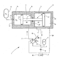
- FIGURE shows a schematic diagram of a hydraulic system with an arrangement of a high-pressure fluid chamber and a low-pressure fluid chamber in a housing of a double-piston accumulator in principle and not to scale.
- a hydraulic system 1 for a work machine for example in the form of a construction machine.
- the hydraulic system 1 in particular its pressure medium pump 2 is driven by a motor unit, not shown internal combustion engine, for example in the form of a diesel engine, with a predeterminable effective drive power.
- the pressure medium pump 2 is reversible in its conveying direction and variably adjustable in its delivery volume.
- the pressure medium pump 2 selectively delivers from a low-pressure fluid chamber 5 (ND) of a double-piston accumulator 6 into a high-pressure fluid chamber 7 (HD) a pressure medium 3 via a fluid-conducting connection 4.
- the pertinent double piston accumulator 6 has a designated as a whole with 16 housing.
- the housing 16 is in the form of a cylinder tube, but may also have other cross-sectional shapes.
- two longitudinally movable pistons 13, 17 are arranged, which are fixedly connected to each other via a coupling element 18 in the form of a coupling rod 19.
- the coupling rod 19 in turn is moved longitudinally with the piston 13, 17 in a partition wall 20 of the housing 16.
- the partition is in the manner of a cylindrical intermediate portion of the housing 16 trained.
- the partition wall 20 with the adjacent opposing pistons 13, 17 defines two fluid spaces in the form of low-pressure fluid chamber 5 and in the form of the high-pressure fluid chamber 7.
- the partition wall 20 corresponding sealing systems, not shown on.
- the housing 16 is delimited by two end walls 21, 22, which form the closure cover of the double-piston accumulator 6. Between the viewed in the direction of the figure left end wall 21 and the adjacent opposite piston 13 is bounded by these parts, a biasing chamber 14 with variable volume, which is a predetermined internal gas pressure via a connection point 23 of a pressure vessel 15 impressed.
- the pressure vessel 15 is preferably designed as a nitrogen storage of conventional design.
- the gas (N 2 ) with prescribable gas pressure located in the preload space 14 forms a type of gas or pressure cushion.
- the opposite piston 17 defines together with the end wall 22 an ambient space 24, which preferably has the respective ambient pressure. In the surrounding space 24, however, another working gas could also be used in a non-illustrated embodiment of the solution according to the invention, such as the nitrogen (N 2 ) mentioned in the prestressing space 14.
- the ambient space 24 is connected via a leak oil line 26 with a pressure medium container 10 (tank) for the purpose of removing leakage oil of the double piston accumulator 6. Furthermore, an accumulator 11 acts on the first fluid-conducting connection 4, which leads from the low-pressure fluid chamber 5 to the pressure medium pump 2. The fluid pressure in the first fluid-conducting connection 4 also serves to act on a pilot control device 12 for influencing the flow rate and the conveying direction of the pressure medium pump 2.
- the volume of the low-pressure fluid chamber 5 is chosen to be much larger than the volume of the high-pressure fluid chamber 7, wherein in the embodiment shown, the inner diameter of the housing part with the low-pressure fluid chamber 5 is chosen to be much larger than that in the housing part of the high-pressure fluid chamber. 7 the case is. In this way, sufficient stored pressure medium, provided for the operation of the hydraulic system 1, so that the pressure medium pump 2 can be supplied safely and permanently with pressure medium even with external or internal leakage volume flows.
- a check valve 8 is provided in the second fluid-carrying connection 9, at a point between the pressure medium tank 10 (tank) and a node 25 between the pressure accumulator 11 and the pressure medium pump second If the low-pressure fluid chamber 5 is undersupplied with the pressure medium, it is possible that pressure medium is sucked in from the pressure medium container 10 via the non-return valve 8 which opens toward the pressure medium pump 2 and supplied to the pressure medium pump 2 under the pretension pressure of the pressure accumulator 11. In this way, a prestressed pressure medium supply to the pressure medium pump 2 is twice possible. In particular, pressure medium 3 is then sucked in from the pressure medium container 10 via the check valve 8 when the pressure medium pump 2 is accelerated and pressure medium is conveyed from the low-pressure fluid space 5 into the high-pressure fluid space 7.
- the double-piston accumulator 6 makes it possible to bias pressure medium 3 flowing as a connecting link from and to the pressure medium pump 2.
- the volume on the low pressure side, that is, in the low pressure fluid space 5, is increased as the volume on the high pressure side, that is, in the high pressure fluid space 7, decreases.
- the double piston accumulator 6 is constructed substantially symmetrically with respect to its longitudinal axis and center axis and thus structurally simple and inexpensive to produce.
Landscapes
- Engineering & Computer Science (AREA)
- General Engineering & Computer Science (AREA)
- Mining & Mineral Resources (AREA)
- Civil Engineering (AREA)
- Structural Engineering (AREA)
- Physics & Mathematics (AREA)
- Fluid Mechanics (AREA)
- Mechanical Engineering (AREA)
- Chemical & Material Sciences (AREA)
- Analytical Chemistry (AREA)
- Fluid-Pressure Circuits (AREA)
- Supply Devices, Intensifiers, Converters, And Telemotors (AREA)
Description
- Die Erfindung betrifft eine hydraulische Anlage, insbesondere für ein Nutzfahrzeug, wie eine Baumaschine, mit einer in der Förderrichtung umkehrbaren und im Fördervolumen variabel einstellbaren Druckmittelpumpe, wobei die Druckmittelpumpe das Druckmittel über eine erste fluidführende Verbindung von einem Niederdruck-Fluidraum eines Doppelkolbenspeichers entnimmt und in einen Hochdruck-Fluidraum des Doppelkolbenspeichers fördert, der zwischen der Druckmittelpumpe und dem Verbraucher angeordnet ist und dass das Volumen des Niederdruck-Fluidraumes größer ist als das Volumen des Hochdruck-Fluidraumes.
- Hydraulische Anlagen für Nutzfahrzeuge, insbesondere für Baumaschinen, Landmaschinen und Off-Road-Arbeitsmaschinen, einschließlich Stapler, setzen sich im Allgemeinen aus mehreren hydrostatischen Antriebssystemen zusammen. Dazu zählen neben der Lenkhydraulik die Kühl-, Steuerungs- und Speisehydraulik sowie die Fahrhydraulik. Diese Systeme können in Abhängigkeit von ihrer Grundstruktur teilweise unabhängig voneinander arbeiten und ihrer jeweiligen Funktion nachkommen.
- Bei fahrenden Baumaschinen ist das Lenksystem regelmäßig mit einem Lenkventil mit sogenannter "offener Mitte" betrieben, wobei eine häufig als Außenzahnradpumpe gebildete Konstantpumpe bei nicht betätigtem Lenksystem gegen den Druckmitteltank der Baumaschine fördert. Bei Personenkraftwagen übernimmt die Förderung von Druckmittel innerhalb eines derart gebildeten offenen Systems meist eine Flügelzellenpumpe mit einstellbarem Verdrängungsvolumen. Durch den Einsatz eines sogenannten offenen Hydraulikkreislaufes können beispielsweise die Funktionen Kühl-, Steuer- und Speisekreislauf mit nur einer Druckmittelpumpe abgedeckt werden. Dabei kann es sich um ein Außenzahnradpumpe mit einem konstanten Verdrängungsvolumen handeln, die an einem Nebenabtrieb der Verbrennungskraftmaschine als Motoreinheit angebracht ist. Nach einem beispielsweise als Außenzahnradkonstantmotor gebildeten Kühlmotor kann eine Parallelverschaltung von Steuer- und Einspeisehydraulikkreislauf vorgesehen sein. Das Steuerdrucksystem dient zur Signalübertragung von bestimmten Maschineneigenschaften, wie der Ansteuerung einer Lamellen-Feststellbremse oder einer Schwenkwinkelverstelleinrichtung der Fahrpumpe mittels Fahrgeberventil. Durch den Einsatz des Speisesystems erfolgt sowohl die Einspeisung von frischem, gereinigten Hydrauliköl als auch ein interner Leckageausgleich.
- Die Auslegung mobiler Arbeitsmaschinen ist in den letzten Jahren zusehends durch die Anforderungen der Europäischen Abgasgesetzgebung geprägt. So gilt seit dem Jahr 2008 für alle Motorleistungsklassen mobiler Arbeitsmaschinen die Europäische Emmissionsrichtlinie IIIA. Nach Inkrafttreten der bereits geschlossenen Abgasstufe IIIB gilt ab dem Jahr 2010 eine weitere Verringerung der Stickoxyde um bis zu 94%, was nach heutiger Auffassung nur durch den Einsatz entsprechender Partikelfilter überhaupt umsetzbar ist. Eine letzte Abgasstufennorm IV 2014 sieht eine weitere Senkung der Stickoxyde um bis 88% gegenüber der Stufe IIIB vor. Insbesondere diese letzte Abgasstufe IV stellt die Baumaschinen- und Dieselmotorenhersteller vor große Herausforderungen. Für die Installation eines selektiven Katalysator-Systems (SCR) nebst dem dazugehörigen Harnstofftank wird zusätzlicher Einbauraum an der jeweiligen Maschine benötigt, was insbesondere bei Groß-Maschinenserien zu einem konstruktiven und logistischen Aufwand führen dürfte.
- Unter Berücksichtigung der aufwendigen Abgasnachbehandlungssysteme und den damit verbundenen Auswirkungen stellt insbesondere die Motorleistungsklasse bis 56kW durch das Wegfallen der EU-Abgasnorm IV eine interessante Alternative für Maschinenhersteller dar. Mittels einer energetischen Optimierung der bestehenden Antriebssysteme ist eine dieselmotorische Leistungsreduzierung bis unterhalb der genannten 56kW-Leistungsgrenze erzielbar, d.h. es wird das sogenannte "downsizing" der Verbrennungskraftmaschine angestrebt.
- Durch die
US 2004/0103656 A1 ist ein Hydraulikenergiespeichersystem im Stand der Technik bekannt, bei dem zwischen einem Hochdruckspeicher und einem Niederdruckspeicher eine Motor-Pumpen-Einheit angeordnet ist. Zur Nachspeisung von Hydraulikflüssigkeit in den Kreislauf sind im Kolben des Niederdruckspeichers Ventile vorgesehen, die abhängig von der Betätigung des Kolbens ein Einspeisen der Hydraulikflüssigkeit in den Niederdruck-Fluidraum und damit den hydraulischen Kreislauf ermöglichen. Aus einem nachveröffentlichten Stand der Technik ist es ferner bekannt, die Leistungsspitzen der Motoreinheit, insbesondere in Form einer Verbrennungskraftmaschine, durch den Einsatz eines Druckmittelspeichers zu kompensieren, wobei der Druckmittelspeicher in Abhängigkeit von einer momentanen Leistungsabgabe der Motoreinheit aufgeladen oder entladen wird. Dadurch lässt sich die Gesamtleistung der Motoreinheit im Sinne von downsizing auf einen vorgebbaren Wert, beispielsweise auf die gesetzlich vorgegebene Motorleistungsklasse bis 56kW, begrenzen. Die Druckmittelzufuhr zu den Verbrauchern und zu einem Druckmittelspeicher der hydraulischen Anlage wird dabei häufig durch ein sogenanntes Prioritätsventil gesteuert. Ein Zu- und Abschalten der Druckmittelzufuhr zu einem oder mehreren Verbrauchern wird durch ein weiteres Ventil gesteuert. - Bei solchen und demgemäß auch bei anderen hydraulischen Anlagen kann Kavitation nicht in jedem Fall ausgeschlossen werden, so dass es wünschenswert ist, das Druckmittel insbesondere in der Saugleitung einer Druckmittelpumpe vorzuspannen. Jede Druckerhöhung führt jedoch bei solchen hydraulischen Anlagen zu einer Reduzierung der Leistung, welche man einem Hybrid entnehmen kann.
- Ausgehend von dem genannten Stand der Technik liegt daher der Erfindung die Aufgabe zugrunde, eine hydraulische Anlage für ein Nutzfahrzeug zu schaffen, die zum einen eine Leistungsminderung für die Verbrennungskraftmaschine erlaubt und bei der zum anderen das Problem der Kavitation gelöst wird.
- Diese Aufgabe wird mit einer hydraulischen Anlage mit den Merkmalen in der Gesamtheit des Patentanspruches 1 gelöst.
- Der Druckmitteldruck in dem Niederdruck-Fluidraum ist dabei derart gewählt, dass dieser ausreichend ist, um eine Vorsteuerungseinrichtung für die Druckmittelpumpe zu betätigen. Die Vorsteuerungseinrichtung kann eine hydraulische, mit einem oder mehreren Stellzylindern versehene Einrichtung sein, um beispielsweise den Verschwenkwinkel eines Kurvenringes einer Flügelzellenpumpe oder dergleichen zu bestimmen und damit die Fördermenge und Förderrichtung der Druckmittelpumpe vorzugeben.
- Dadurch, dass saugseitig der Druckmittelpumpe ein Druckmittel von einem Niederdruck-Fluidraum der hydraulischen Anlage entnommen und in einen Hochdruck-Fluidraum der hydraulischen Anlage gefördert wird, ist eine konstruktive Maßnahme getroffen, das von der Druckmittelpumpe angesaugte Druckmittel immer geringfügig bzw. derart vorzuspannen, dass die Kavitation in der hydraulischen Anlage vermieden ist. Zudem ist das Volumen des Niederdruck-Fluidraumes größer oder wesentlich größer als das Volumen des Hochdruck-Fluidraumes, so dass in jeder Betriebsphase der hydraulischen Anlage sichergestellt ist, dass genügend vorgespanntes Druckmittel der Druckmittelpumpe zuführbar ist. Das Volumen des Niederdruck-Fluidraumes ist derart bemessen, dass auch Leckölverluste der hydraulischen Anlage keinen Einfluss auf deren Betrieb haben.
- Bevorzugte Ausführungsformen der erfindungsgemäßen Lösung ergeben sich aus den Unteransprüchen.
- In einem besonders bevorzugten Ausführungsbeispiel der hydraulischen Anlage lässt sich der Niederdruck-Fluidraum aus dem Druckmittel entnommen wird, bzw. die fluidführende Verbindung zwischen Niederdruck-Fluidraum und der Druckmittelpumpe an eine fluidführende Verbindung zu dem Druckmittelbehälter anbinden. Insbesondere dient hierfür ein Rückschlagventil, das einen Zustrom in die genannte fluidführende Verbindung oder in den Niederdruck-Fluidraum nur ermöglicht, wenn die Druckmittelpumpe in einer Drehrichtungs-Umkehrphase, etwa beim Beschleunigen, durch einen durch sie geführten Druckmittelrückfluss von dem Verbraucher, Druckmittel in den Hochdruck-Fluidraum pumpt. Dabei öffnet das Rückschlagventil und ermöglicht ein Abziehen von Druckmittel aus dem Druckmittelbehälter durch Unterdruck in der genannten fluidführenden Verbindung.
- Vorzugsweise kann der Kolben des Hochdruck-Fluidraumes von einem Gasdruck eines Vorspannraumes, wie erwähnt, vorgespannt sein. Der Vorspannraum kann von einem Gasdruck in einer Gasversorgungseinrichtung beaufschlagt sein. Zu diesem Zweck ist der Vorspannraum von einer feststehenden Abschlusswand des Gehäuses des Hochdruck-Fluidraumes oder des Doppelkolbenspeichers begrenzt. Die Abschlusswand weist vorzugsweise eine Anschlussstelle für die Gasversorgungseinrichtung auf, beispielsweise in der Art eines Stickstoffspeichers.
- Im Folgenden wird die erfindungsgemäße hydraulische Anlage anhand eines Ausführungsbeispieles nach der Zeichnung näher erläutert. Dabei zeigt in prinzipieller und nicht maßstäblicher Darstellung die einzige Figur ein schematisches Schaltbild einer hydraulischen Anlage mit einer Anordnung eines Hochdruck-Fluidraumes und eines Niederdruck-Fluidraumes in einem Gehäuse eines Doppelkolbenspeichers.
- In der Figur ist in einem schematischen Schaltbild und in einem teilweise Längsschnitt sowie prinzipiell eine hydraulische Anlage 1 für eine Arbeitsmaschine, beispielsweise in Form einer Baumaschine dargestellt. Die hydraulische Anlage 1, insbesondere deren Druckmittelpumpe 2, wird von einer als Motoreinheit ausgebildeten, nicht dargestellten Verbrennungskraftmaschine, beispielsweise in Form eines Dieselmotors, mit einer vorgebbaren effektiven Antriebsleistung angetrieben. Die Druckmittelpumpe 2 ist in ihrer Förderrichtung umkehrbar und in ihrem Fördervolumen variabel einstellbar. Die Druckmittelpumpe 2 fördert wahlweise aus einem Niederdruck-Fluidraum 5 (ND) eines Doppelkolbenspeichers 6 in einen Hochdruck-Fluidraum 7 (HD) ein Druckmittel 3 über eine fluidführende Verbindung 4.
- Der dahingehende Doppelkolbenspeicher 6 weist ein als Ganzes mit 16 bezeichnetes Gehäuse auf. Das Gehäuse 16 ist in Form eines Zylinderrohres ausgebildet, kann aber auch andere Querschnittsformen aufweisen. In dem Gehäuse sind zwei längsverfahrbare Kolben 13, 17 angeordnet, die über ein Koppelelement 18 in Form einer Koppelstange 19 miteinander fest verbunden sind. Die Koppelstange 19 wiederum ist längsverfahrbar mit dem Kolben 13, 17 in einer Trennwand 20 des Gehäuses 16 geführt. Die Trennwand ist in der Art eines zylindrischen Zwischenabschnittes des Gehäuses 16 ausgebildet. Ferner begrenzt die Trennwand 20 mit den benachbart gegenüberliegenden Kolben 13, 17 zwei Fluidräume in Form des Niederdruck-Fluidraumes 5 und in Form des Hochdruck-Fluidraumes 7. Zur Abdichtung der beiden Fluidräume 5, 7 voneinander weist die Trennwand 20 entsprechende, nicht näher dargestellte Dichtsysteme auf.
- Das Gehäuse 16 ist endseitig von zwei Abschlusswänden 21, 22 begrenzt, die die Verschlussdeckel des Doppelkolbenspeichers 6 ausbilden. Zwischen der in Blickrichtung auf die Figur gesehen linken Abschlusswand 21 und dem benachbart gegenüberliegenden Kolben 13 befindet sich von diesen Teilen begrenzt, ein Vorspannraum 14 mit variablem Volumen, dem ein vorgebbarer Gasinnendruck über eine Anschlussstelle 23 eines Druckbehälters 15 aufgeprägt ist. Der Druckbehälter 15 ist bevorzugt als Stickstoffspeicher üblicher Bauart ausgebildet. Das in dem Vorspannraum 14 befindliche Gas (N2) mit vorgebbarem Gasdruck bildet eine Art Gas- oder Druckpolster aus. Der gegenüberliegende Kolben 17 begrenzt zusammen mit der Abschlusswand 22 einen Umgebungsraum 24, der bevorzugt den jeweiligen Umgebungsdruck aufweist. In dem Umgebungsraum 24 könnte aber auch bei einer nicht näher dargestellten Ausführungsform der erfindungsgemäßen Lösung ein anderes Arbeitsgas Verwendung finden, wie etwa der genannte Stickstoff (N2) im Vorspannraum 14.
- Der Umgebungsraum 24 ist über eine Leckölleitung 26 mit einem Druckmittelbehälter 10 (Tank) verbunden zwecks Abfuhr von Leckageöl des Doppelkolbenspeichers 6. Des weiteren beaufschlagt ein Druckspeicher 11 die erste fluidführende Verbindung 4, die von dem Niederdruck-Fluidraum 5 zu der Druckmittelpumpe 2 führt. Der Fluiddruck in der ersten fluidführenden Verbindung 4 dient ferner zur Beaufschlagung einer Vorsteuereinrichtung 12, für das Beeinflussen der Fördermenge und der Förderrichtung der Druckmittelpumpe 2.
- Stromauf ist auf der in der Figur dargestellten Hochdruckseite der Druckmittelpumpe 2 diese mit dem Hochdruck-Fluidraum 7 des Doppelkolbenspeichers 6 verbunden. Um einen kontinuierlichen Betrieb der hydraulischen Anlage 1 zu gewährleisten und insbesondere Druckmittel-Unterversorgung der aus dem Niederdruck-Fluidraum 5 fördernden Druckmittelpumpe 2 zu vermeiden, sind zumindest zwei konstruktive Maßnahmen vorgesehen. So ist das Volumen des Niederdruck-Fluidraumes 5 wesentlich größer gewählt als das Volumen des Hochdruck-Fluidraumes 7, wobei in dem gezeigten Ausführungsbeispiel der Innendurchmesser des Gehäuseteils mit dem Niederdruck-Fluidraum 5 wesentlich größer gewählt ist als dies bei dem Gehäuseteil des Hochdruck-Fluidraumes 7 der Fall ist. Auf diese Weise ist für den Betrieb der hydraulischen Anlage 1 genügend gespeichertes Druckmittel, zur Verfügung gestellt, so dass die Druckmittelpumpe 2 auch bei externen oder internen Leckvolumenströmen sicher sowie dauerhaft mit Druckmittel versorgt werden kann.
- Eine zweite konstruktive Maßnahme zur Gewährleistung eines steten Zuflusses von vorgespanntem Druckmittel, ist ein Rückschlagventil 8 in der zweiten fluidführenden Verbindung 9 vorzusehen, und zwar an einer Stelle zwischen dem Druckmittelbehälter 10 (Tank) und einem Knotenpunkt 25 zwischen dem Druckspeicher 11 und der Druckmittelpumpe 2. Sollte der Niederdruck-Fluidraum 5 mit dem Druckmittel unterversorgt sein, so besteht die Möglichkeit, dass über das zu der Druckmittelpumpe 2 hin öffnende Rückschlagventil 8 Druckmittel aus dem Druckmittelbehälter 10 angesaugt und unter dem Vorspanndruck des Druckspeichers 11 der Druckmittelpumpe 2 zugeführt wird. Auf diese Weise ist zweifach eine vorgespannte Druckmittelzufuhr zu der Druckmittelpumpe 2 ermöglicht. Insbesondere wird über das Rückschlagventil 8 dann Druckmittel 3 aus dem Druckmittelbehälter 10 nachgesaugt, wenn ein Beschleunigen der Druckmittelpumpe 2 erfolgt und Druckmittel von dem Niederdruck-Fluidraum 5 in den Hochdruck-Fluidraum 7 gefördert wird.
- Der Doppelkolbenspeicher 6 ermöglicht als Bindeglied von und zu der Druckmittelpumpe 2 strömendes Druckmittel 3 vorzuspannen. Das Volumen auf der Niederdruckseite, also in dem Niederdruck-Fluidraum 5 wird in dem Maße vergrößert, wie sich das Volumen auf der Hochdruckseite, also in dem Hochdruck-Fluidraum 7 verringert. Der Doppelkolbenspeicher 6 ist in Bezug auf seine Längsachse und Mittenachse im Wesentlichen symmetrisch aufgebaut und somit konstruktiv einfach und kostengünstig herstellbar.
Claims (5)
- Hydraulische Anlage, insbesondere für ein Nutzfahrzeug, wie einer Baumaschine, mit einer in der Förderrichtung umkehrbaren und im Fördervolumen variabel einstellbaren Druckmittelpumpe (2), wobei die Druckmittelpumpe (2) das Druckmittel (3) über eine erste fluidführende Verbindung (4) von einem Niederdruck-Fluidraum (5) eines Doppelkolbenspeichers (6) entnimmt und in einen Hochdruck-Fluidraum (7) des Doppelkolbenspeichers (6) fördert, der zwischen der Druckmittelpumpe (2) und dem Verbraucher angeordnet ist und wobei das Volumen des Niederdruck-Fluidraumes (5) größer ist als das Volumen des Hochdruck-Fluidraumes (7), dadurch gekennzeichnet, dass das Druckmittel (3) in dem Niederdruck-Fluidraum (5) zur Versorgung einer Vorsteuerungseinrichtung (12) für die Fördermenge und Förderrichtung der Druckmittelpumpe (2) dient.
- Hydraulische Anlage nach Anspruch 1, dadurch gekennzeichnet, dass der Niederdruck-Fluidraum (5) über ein in Richtung auf die Druckmittelpumpe (2) öffnendes Rückschlagventil (8) mit einer zweiten fluidführenden Verbindung (9) mit dem Druckmittelbehälter (10) verbunden ist.
- Hydraulische Anlage nach Anspruch 1 oder 2, dadurch gekennzeichnet, dass die erste oder zweite fluidführende Verbindung (4, 9) mit einem Druckmittelspeicher (11) zwischen dem Rückschlagventil (8) und der Druckmittelpumpe (2) verbunden ist.
- Hydraulische Anlage nach einem der Ansprüche 1 bis 3, dadurch gekennzeichnet, dass zumindest ein Kolben (13) des Doppelkolbenspeichers (6) einen Vorspannraum (14) mit einem vorgebbaren Gasinnendruck begrenzt und dass der Vorspannraum (14) mit einem Druckbehälter (15) verbunden ist.
- Hydraulische Anlage nach einem der vorhergehenden Ansprüche, dadurch gekennzeichnet, dass die Druckmittelpumpe (2) das Druckmittel (3) über eine erste fluidführende Verbindung (4) von einem Niederdruck-Fluidraum (5) eines Doppelkolbenspeichers (6) entnimmt und in einen Hochdruck-Fluidraum (7) des Doppelkolbenspeichers (6) fördert, deren Fluidvolumina (5,7) mechanisch gekoppelt sind.
Applications Claiming Priority (2)
| Application Number | Priority Date | Filing Date | Title |
|---|---|---|---|
| DE102010023016A DE102010023016A1 (de) | 2010-06-08 | 2010-06-08 | Hydraulische Anlage |
| PCT/EP2011/002642 WO2011154101A1 (de) | 2010-06-08 | 2011-05-27 | Hydraulische anlage |
Publications (2)
| Publication Number | Publication Date |
|---|---|
| EP2580080A1 EP2580080A1 (de) | 2013-04-17 |
| EP2580080B1 true EP2580080B1 (de) | 2014-08-27 |
Family
ID=44118838
Family Applications (1)
| Application Number | Title | Priority Date | Filing Date |
|---|---|---|---|
| EP11722019.4A Not-in-force EP2580080B1 (de) | 2010-06-08 | 2011-05-27 | Hydraulische anlage |
Country Status (3)
| Country | Link |
|---|---|
| EP (1) | EP2580080B1 (de) |
| DE (1) | DE102010023016A1 (de) |
| WO (1) | WO2011154101A1 (de) |
Families Citing this family (3)
| Publication number | Priority date | Publication date | Assignee | Title |
|---|---|---|---|---|
| US9790962B2 (en) * | 2011-10-10 | 2017-10-17 | Angus Peter Robson | Accumulator |
| CN104564577A (zh) * | 2013-10-29 | 2015-04-29 | 北京精密机电控制设备研究所 | 一种伺服电动泵 |
| JP7484312B2 (ja) * | 2020-03-27 | 2024-05-16 | Smc株式会社 | 増圧出力安定化装置 |
Family Cites Families (7)
| Publication number | Priority date | Publication date | Assignee | Title |
|---|---|---|---|---|
| US2286798A (en) * | 1940-05-16 | 1942-06-16 | Hydraulic Dev Corp Inc | Hydraulic circuit for press brakes |
| DE3829646A1 (de) * | 1988-09-01 | 1990-03-15 | Teves Gmbh Alfred | Reservoir fuer einen druckmittelkreis, insbesondere flugzeughydraulikkreis |
| FR2786442B1 (fr) * | 1998-12-01 | 2001-03-02 | Peugeot | Dispositif formant toit coulissant de vehicule automobile |
| AUPR170400A0 (en) * | 2000-11-28 | 2000-12-21 | Ifield Technology Ltd | Emergency energy release for hydraulic energy storage systems |
| WO2002043980A2 (en) * | 2000-11-28 | 2002-06-06 | Shep Limited | Hydraulic energy storage systems |
| DE102006048399B4 (de) * | 2006-10-12 | 2018-05-09 | Liebherr-Aerospace Lindenberg Gmbh | Vorrichtung zur Entriegelung eines Bauteils eines Flugzeuges |
| US7926501B2 (en) * | 2007-02-07 | 2011-04-19 | National Oilwell Varco L.P. | Subsea pressure systems for fluid recovery |
-
2010
- 2010-06-08 DE DE102010023016A patent/DE102010023016A1/de not_active Withdrawn
-
2011
- 2011-05-27 WO PCT/EP2011/002642 patent/WO2011154101A1/de not_active Ceased
- 2011-05-27 EP EP11722019.4A patent/EP2580080B1/de not_active Not-in-force
Also Published As
| Publication number | Publication date |
|---|---|
| WO2011154101A1 (de) | 2011-12-15 |
| DE102010023016A1 (de) | 2011-12-08 |
| EP2580080A1 (de) | 2013-04-17 |
Similar Documents
| Publication | Publication Date | Title |
|---|---|---|
| EP2786025B1 (de) | System zur verbesserung der energieeffizienz bei hydrauliksystemen, für ein derartiges system vorgesehener kolbenspeicher und druckspeicher | |
| EP2550170B1 (de) | Hydrostatisches hybrid-antriebssystem | |
| DE3142604C2 (de) | ||
| DE102011120227B4 (de) | Hydraulisches Hybridsystem für rotatorische Anwendungen | |
| DE102009008850B4 (de) | Variable Verdrängergetriebepumpe | |
| EP2307726B1 (de) | Verstellpumpe mit einem mengenregler und einem druckventil. | |
| EP2834542B1 (de) | Geschlossener hydraulischer kreislauf | |
| DE10209880A1 (de) | System zur Steuerung einer hydraulischen Verstellpumpe | |
| EP2251549B1 (de) | Hydraulische Anlage | |
| EP3786460B1 (de) | Fluidrückführvorrichtung für einen doppeltwirkenden pneumatikzylinder und verfahren zum betreiben eines solchen pneumatikzylinders | |
| EP2580080B1 (de) | Hydraulische anlage | |
| DE102007016145A1 (de) | Flügelzellenpumpe | |
| DE102010031817A1 (de) | Hydraulisches Getriebe | |
| DE102012202904A1 (de) | Pumpenanordnung zum Erzeugen eines variablen Volumenstromes | |
| DE19527402A1 (de) | Pumpe | |
| DE102008058288A1 (de) | Druckbegrenzungsventil und Hochdruckpumpe mit einem Druckbegrenzungsventil | |
| EP1564414A1 (de) | Hydraulischer Antrieb | |
| DE102010038863A1 (de) | Hydraulische Pumpe | |
| DE102010023015B4 (de) | Hydraulische Anlage | |
| DE102009060188A1 (de) | Verstellventil für die Verstellung des Fördervolumens einer Verdrängerpumpe mit Kaltstartfunktion | |
| DE102011079311A1 (de) | Kühlmittelpumpe für einen Kühlmittelkreiskreislauf einer Brennkraftmaschine | |
| DE102009037198A1 (de) | Hydraulische Steueranordnung | |
| EP2342118B1 (de) | Hydraulische servolenkung | |
| WO2014016054A1 (de) | Hydrostatische axialkolbenmaschine | |
| DE4240590A1 (de) | Verdrängerpumpe |
Legal Events
| Date | Code | Title | Description |
|---|---|---|---|
| PUAI | Public reference made under article 153(3) epc to a published international application that has entered the european phase |
Free format text: ORIGINAL CODE: 0009012 |
|
| 17P | Request for examination filed |
Effective date: 20121109 |
|
| AK | Designated contracting states |
Kind code of ref document: A1 Designated state(s): AL AT BE BG CH CY CZ DE DK EE ES FI FR GB GR HR HU IE IS IT LI LT LU LV MC MK MT NL NO PL PT RO RS SE SI SK SM TR |
|
| DAX | Request for extension of the european patent (deleted) | ||
| REG | Reference to a national code |
Ref country code: DE Ref legal event code: R079 Ref document number: 502011004198 Country of ref document: DE Free format text: PREVIOUS MAIN CLASS: B60K0006120000 Ipc: E02F0009220000 |
|
| RIC1 | Information provided on ipc code assigned before grant |
Ipc: F15B 1/24 20060101ALI20140304BHEP Ipc: F15B 21/04 20060101ALI20140304BHEP Ipc: E02F 9/22 20060101AFI20140304BHEP Ipc: F15B 1/02 20060101ALI20140304BHEP |
|
| GRAP | Despatch of communication of intention to grant a patent |
Free format text: ORIGINAL CODE: EPIDOSNIGR1 |
|
| INTG | Intention to grant announced |
Effective date: 20140513 |
|
| GRAS | Grant fee paid |
Free format text: ORIGINAL CODE: EPIDOSNIGR3 |
|
| GRAA | (expected) grant |
Free format text: ORIGINAL CODE: 0009210 |
|
| AK | Designated contracting states |
Kind code of ref document: B1 Designated state(s): AL AT BE BG CH CY CZ DE DK EE ES FI FR GB GR HR HU IE IS IT LI LT LU LV MC MK MT NL NO PL PT RO RS SE SI SK SM TR |
|
| REG | Reference to a national code |
Ref country code: GB Ref legal event code: FG4D Free format text: NOT ENGLISH |
|
| REG | Reference to a national code |
Ref country code: CH Ref legal event code: EP |
|
| REG | Reference to a national code |
Ref country code: AT Ref legal event code: REF Ref document number: 684616 Country of ref document: AT Kind code of ref document: T Effective date: 20140915 |
|
| REG | Reference to a national code |
Ref country code: IE Ref legal event code: FG4D Free format text: LANGUAGE OF EP DOCUMENT: GERMAN |
|
| REG | Reference to a national code |
Ref country code: DE Ref legal event code: R096 Ref document number: 502011004198 Country of ref document: DE Effective date: 20141009 |
|
| REG | Reference to a national code |
Ref country code: SE Ref legal event code: TRGR |
|
| REG | Reference to a national code |
Ref country code: LT Ref legal event code: MG4D |
|
| REG | Reference to a national code |
Ref country code: NL Ref legal event code: VDEP Effective date: 20140827 |
|
| PG25 | Lapsed in a contracting state [announced via postgrant information from national office to epo] |
Ref country code: PT Free format text: LAPSE BECAUSE OF FAILURE TO SUBMIT A TRANSLATION OF THE DESCRIPTION OR TO PAY THE FEE WITHIN THE PRESCRIBED TIME-LIMIT Effective date: 20141229 Ref country code: BG Free format text: LAPSE BECAUSE OF FAILURE TO SUBMIT A TRANSLATION OF THE DESCRIPTION OR TO PAY THE FEE WITHIN THE PRESCRIBED TIME-LIMIT Effective date: 20141127 Ref country code: NO Free format text: LAPSE BECAUSE OF FAILURE TO SUBMIT A TRANSLATION OF THE DESCRIPTION OR TO PAY THE FEE WITHIN THE PRESCRIBED TIME-LIMIT Effective date: 20141127 Ref country code: FI Free format text: LAPSE BECAUSE OF FAILURE TO SUBMIT A TRANSLATION OF THE DESCRIPTION OR TO PAY THE FEE WITHIN THE PRESCRIBED TIME-LIMIT Effective date: 20140827 Ref country code: GR Free format text: LAPSE BECAUSE OF FAILURE TO SUBMIT A TRANSLATION OF THE DESCRIPTION OR TO PAY THE FEE WITHIN THE PRESCRIBED TIME-LIMIT Effective date: 20141128 Ref country code: LT Free format text: LAPSE BECAUSE OF FAILURE TO SUBMIT A TRANSLATION OF THE DESCRIPTION OR TO PAY THE FEE WITHIN THE PRESCRIBED TIME-LIMIT Effective date: 20140827 Ref country code: ES Free format text: LAPSE BECAUSE OF FAILURE TO SUBMIT A TRANSLATION OF THE DESCRIPTION OR TO PAY THE FEE WITHIN THE PRESCRIBED TIME-LIMIT Effective date: 20140827 |
|
| PG25 | Lapsed in a contracting state [announced via postgrant information from national office to epo] |
Ref country code: HR Free format text: LAPSE BECAUSE OF FAILURE TO SUBMIT A TRANSLATION OF THE DESCRIPTION OR TO PAY THE FEE WITHIN THE PRESCRIBED TIME-LIMIT Effective date: 20140827 Ref country code: IS Free format text: LAPSE BECAUSE OF FAILURE TO SUBMIT A TRANSLATION OF THE DESCRIPTION OR TO PAY THE FEE WITHIN THE PRESCRIBED TIME-LIMIT Effective date: 20141227 Ref country code: CY Free format text: LAPSE BECAUSE OF FAILURE TO SUBMIT A TRANSLATION OF THE DESCRIPTION OR TO PAY THE FEE WITHIN THE PRESCRIBED TIME-LIMIT Effective date: 20140827 Ref country code: RS Free format text: LAPSE BECAUSE OF FAILURE TO SUBMIT A TRANSLATION OF THE DESCRIPTION OR TO PAY THE FEE WITHIN THE PRESCRIBED TIME-LIMIT Effective date: 20140827 Ref country code: LV Free format text: LAPSE BECAUSE OF FAILURE TO SUBMIT A TRANSLATION OF THE DESCRIPTION OR TO PAY THE FEE WITHIN THE PRESCRIBED TIME-LIMIT Effective date: 20140827 |
|
| PG25 | Lapsed in a contracting state [announced via postgrant information from national office to epo] |
Ref country code: NL Free format text: LAPSE BECAUSE OF FAILURE TO SUBMIT A TRANSLATION OF THE DESCRIPTION OR TO PAY THE FEE WITHIN THE PRESCRIBED TIME-LIMIT Effective date: 20140827 |
|
| PG25 | Lapsed in a contracting state [announced via postgrant information from national office to epo] |
Ref country code: RO Free format text: LAPSE BECAUSE OF FAILURE TO SUBMIT A TRANSLATION OF THE DESCRIPTION OR TO PAY THE FEE WITHIN THE PRESCRIBED TIME-LIMIT Effective date: 20140827 Ref country code: CZ Free format text: LAPSE BECAUSE OF FAILURE TO SUBMIT A TRANSLATION OF THE DESCRIPTION OR TO PAY THE FEE WITHIN THE PRESCRIBED TIME-LIMIT Effective date: 20140827 Ref country code: SK Free format text: LAPSE BECAUSE OF FAILURE TO SUBMIT A TRANSLATION OF THE DESCRIPTION OR TO PAY THE FEE WITHIN THE PRESCRIBED TIME-LIMIT Effective date: 20140827 Ref country code: EE Free format text: LAPSE BECAUSE OF FAILURE TO SUBMIT A TRANSLATION OF THE DESCRIPTION OR TO PAY THE FEE WITHIN THE PRESCRIBED TIME-LIMIT Effective date: 20140827 Ref country code: DK Free format text: LAPSE BECAUSE OF FAILURE TO SUBMIT A TRANSLATION OF THE DESCRIPTION OR TO PAY THE FEE WITHIN THE PRESCRIBED TIME-LIMIT Effective date: 20140827 |
|
| REG | Reference to a national code |
Ref country code: DE Ref legal event code: R097 Ref document number: 502011004198 Country of ref document: DE |
|
| PG25 | Lapsed in a contracting state [announced via postgrant information from national office to epo] |
Ref country code: PL Free format text: LAPSE BECAUSE OF FAILURE TO SUBMIT A TRANSLATION OF THE DESCRIPTION OR TO PAY THE FEE WITHIN THE PRESCRIBED TIME-LIMIT Effective date: 20140827 |
|
| PLBE | No opposition filed within time limit |
Free format text: ORIGINAL CODE: 0009261 |
|
| STAA | Information on the status of an ep patent application or granted ep patent |
Free format text: STATUS: NO OPPOSITION FILED WITHIN TIME LIMIT |
|
| 26N | No opposition filed |
Effective date: 20150528 |
|
| PG25 | Lapsed in a contracting state [announced via postgrant information from national office to epo] |
Ref country code: SI Free format text: LAPSE BECAUSE OF FAILURE TO SUBMIT A TRANSLATION OF THE DESCRIPTION OR TO PAY THE FEE WITHIN THE PRESCRIBED TIME-LIMIT Effective date: 20140827 |
|
| REG | Reference to a national code |
Ref country code: CH Ref legal event code: PL |
|
| GBPC | Gb: european patent ceased through non-payment of renewal fee |
Effective date: 20150527 |
|
| PG25 | Lapsed in a contracting state [announced via postgrant information from national office to epo] |
Ref country code: CH Free format text: LAPSE BECAUSE OF NON-PAYMENT OF DUE FEES Effective date: 20150531 Ref country code: LI Free format text: LAPSE BECAUSE OF NON-PAYMENT OF DUE FEES Effective date: 20150531 Ref country code: MC Free format text: LAPSE BECAUSE OF FAILURE TO SUBMIT A TRANSLATION OF THE DESCRIPTION OR TO PAY THE FEE WITHIN THE PRESCRIBED TIME-LIMIT Effective date: 20140827 Ref country code: LU Free format text: LAPSE BECAUSE OF FAILURE TO SUBMIT A TRANSLATION OF THE DESCRIPTION OR TO PAY THE FEE WITHIN THE PRESCRIBED TIME-LIMIT Effective date: 20150527 |
|
| REG | Reference to a national code |
Ref country code: IE Ref legal event code: MM4A |
|
| REG | Reference to a national code |
Ref country code: FR Ref legal event code: PLFP Year of fee payment: 6 |
|
| PG25 | Lapsed in a contracting state [announced via postgrant information from national office to epo] |
Ref country code: IE Free format text: LAPSE BECAUSE OF NON-PAYMENT OF DUE FEES Effective date: 20150527 Ref country code: GB Free format text: LAPSE BECAUSE OF NON-PAYMENT OF DUE FEES Effective date: 20150527 |
|
| PG25 | Lapsed in a contracting state [announced via postgrant information from national office to epo] |
Ref country code: MT Free format text: LAPSE BECAUSE OF FAILURE TO SUBMIT A TRANSLATION OF THE DESCRIPTION OR TO PAY THE FEE WITHIN THE PRESCRIBED TIME-LIMIT Effective date: 20140827 |
|
| REG | Reference to a national code |
Ref country code: FR Ref legal event code: PLFP Year of fee payment: 7 |
|
| PG25 | Lapsed in a contracting state [announced via postgrant information from national office to epo] |
Ref country code: HU Free format text: LAPSE BECAUSE OF FAILURE TO SUBMIT A TRANSLATION OF THE DESCRIPTION OR TO PAY THE FEE WITHIN THE PRESCRIBED TIME-LIMIT; INVALID AB INITIO Effective date: 20110527 Ref country code: SM Free format text: LAPSE BECAUSE OF FAILURE TO SUBMIT A TRANSLATION OF THE DESCRIPTION OR TO PAY THE FEE WITHIN THE PRESCRIBED TIME-LIMIT Effective date: 20140827 |
|
| REG | Reference to a national code |
Ref country code: AT Ref legal event code: MM01 Ref document number: 684616 Country of ref document: AT Kind code of ref document: T Effective date: 20160527 |
|
| PG25 | Lapsed in a contracting state [announced via postgrant information from national office to epo] |
Ref country code: BE Free format text: LAPSE BECAUSE OF NON-PAYMENT OF DUE FEES Effective date: 20150531 |
|
| PG25 | Lapsed in a contracting state [announced via postgrant information from national office to epo] |
Ref country code: TR Free format text: LAPSE BECAUSE OF FAILURE TO SUBMIT A TRANSLATION OF THE DESCRIPTION OR TO PAY THE FEE WITHIN THE PRESCRIBED TIME-LIMIT Effective date: 20140827 Ref country code: AT Free format text: LAPSE BECAUSE OF NON-PAYMENT OF DUE FEES Effective date: 20160527 |
|
| REG | Reference to a national code |
Ref country code: FR Ref legal event code: PLFP Year of fee payment: 8 |
|
| PG25 | Lapsed in a contracting state [announced via postgrant information from national office to epo] |
Ref country code: MK Free format text: LAPSE BECAUSE OF FAILURE TO SUBMIT A TRANSLATION OF THE DESCRIPTION OR TO PAY THE FEE WITHIN THE PRESCRIBED TIME-LIMIT Effective date: 20140827 |
|
| PGFP | Annual fee paid to national office [announced via postgrant information from national office to epo] |
Ref country code: DE Payment date: 20180531 Year of fee payment: 8 |
|
| PGFP | Annual fee paid to national office [announced via postgrant information from national office to epo] |
Ref country code: IT Payment date: 20180514 Year of fee payment: 8 Ref country code: FR Payment date: 20180404 Year of fee payment: 8 |
|
| PGFP | Annual fee paid to national office [announced via postgrant information from national office to epo] |
Ref country code: SE Payment date: 20180404 Year of fee payment: 8 |
|
| PG25 | Lapsed in a contracting state [announced via postgrant information from national office to epo] |
Ref country code: AL Free format text: LAPSE BECAUSE OF FAILURE TO SUBMIT A TRANSLATION OF THE DESCRIPTION OR TO PAY THE FEE WITHIN THE PRESCRIBED TIME-LIMIT Effective date: 20140827 |
|
| REG | Reference to a national code |
Ref country code: DE Ref legal event code: R119 Ref document number: 502011004198 Country of ref document: DE |
|
| PG25 | Lapsed in a contracting state [announced via postgrant information from national office to epo] |
Ref country code: SE Free format text: LAPSE BECAUSE OF NON-PAYMENT OF DUE FEES Effective date: 20190528 |
|
| PG25 | Lapsed in a contracting state [announced via postgrant information from national office to epo] |
Ref country code: DE Free format text: LAPSE BECAUSE OF NON-PAYMENT OF DUE FEES Effective date: 20191203 Ref country code: IT Free format text: LAPSE BECAUSE OF NON-PAYMENT OF DUE FEES Effective date: 20190527 |
|
| REG | Reference to a national code |
Ref country code: SE Ref legal event code: EUG |
|
| PG25 | Lapsed in a contracting state [announced via postgrant information from national office to epo] |
Ref country code: FR Free format text: LAPSE BECAUSE OF NON-PAYMENT OF DUE FEES Effective date: 20190531 |