EP2580113B1 - Trimaran mit schwenkbarem ausleger - Google Patents
Trimaran mit schwenkbarem ausleger Download PDFInfo
- Publication number
- EP2580113B1 EP2580113B1 EP11728797.9A EP11728797A EP2580113B1 EP 2580113 B1 EP2580113 B1 EP 2580113B1 EP 11728797 A EP11728797 A EP 11728797A EP 2580113 B1 EP2580113 B1 EP 2580113B1
- Authority
- EP
- European Patent Office
- Prior art keywords
- main hull
- outrigger
- watercraft
- watercraft according
- arms
- Prior art date
- Legal status (The legal status is an assumption and is not a legal conclusion. Google has not performed a legal analysis and makes no representation as to the accuracy of the status listed.)
- Active
Links
Images




Classifications
-
- B—PERFORMING OPERATIONS; TRANSPORTING
- B63—SHIPS OR OTHER WATERBORNE VESSELS; RELATED EQUIPMENT
- B63B—SHIPS OR OTHER WATERBORNE VESSELS; EQUIPMENT FOR SHIPPING
- B63B43/00—Improving safety of vessels, e.g. damage control, not otherwise provided for
- B63B43/02—Improving safety of vessels, e.g. damage control, not otherwise provided for reducing risk of capsizing or sinking
- B63B43/10—Improving safety of vessels, e.g. damage control, not otherwise provided for reducing risk of capsizing or sinking by improving buoyancy
- B63B43/14—Improving safety of vessels, e.g. damage control, not otherwise provided for reducing risk of capsizing or sinking by improving buoyancy using outboard floating members
-
- B—PERFORMING OPERATIONS; TRANSPORTING
- B63—SHIPS OR OTHER WATERBORNE VESSELS; RELATED EQUIPMENT
- B63B—SHIPS OR OTHER WATERBORNE VESSELS; EQUIPMENT FOR SHIPPING
- B63B1/00—Hydrodynamic or hydrostatic features of hulls or of hydrofoils
- B63B1/02—Hydrodynamic or hydrostatic features of hulls or of hydrofoils deriving lift mainly from water displacement
- B63B1/10—Hydrodynamic or hydrostatic features of hulls or of hydrofoils deriving lift mainly from water displacement with multiple hulls
- B63B1/14—Hydrodynamic or hydrostatic features of hulls or of hydrofoils deriving lift mainly from water displacement with multiple hulls the hulls being interconnected resiliently or having means for actively varying hull shape or configuration
-
- B—PERFORMING OPERATIONS; TRANSPORTING
- B63—SHIPS OR OTHER WATERBORNE VESSELS; RELATED EQUIPMENT
- B63B—SHIPS OR OTHER WATERBORNE VESSELS; EQUIPMENT FOR SHIPPING
- B63B1/00—Hydrodynamic or hydrostatic features of hulls or of hydrofoils
- B63B1/02—Hydrodynamic or hydrostatic features of hulls or of hydrofoils deriving lift mainly from water displacement
- B63B1/10—Hydrodynamic or hydrostatic features of hulls or of hydrofoils deriving lift mainly from water displacement with multiple hulls
-
- B—PERFORMING OPERATIONS; TRANSPORTING
- B63—SHIPS OR OTHER WATERBORNE VESSELS; RELATED EQUIPMENT
- B63B—SHIPS OR OTHER WATERBORNE VESSELS; EQUIPMENT FOR SHIPPING
- B63B1/00—Hydrodynamic or hydrostatic features of hulls or of hydrofoils
- B63B1/16—Hydrodynamic or hydrostatic features of hulls or of hydrofoils deriving additional lift from hydrodynamic forces
- B63B1/24—Hydrodynamic or hydrostatic features of hulls or of hydrofoils deriving additional lift from hydrodynamic forces of hydrofoil type
- B63B1/28—Hydrodynamic or hydrostatic features of hulls or of hydrofoils deriving additional lift from hydrodynamic forces of hydrofoil type with movable hydrofoils
- B63B1/30—Hydrodynamic or hydrostatic features of hulls or of hydrofoils deriving additional lift from hydrodynamic forces of hydrofoil type with movable hydrofoils retracting or folding
Definitions
- the present invention relates to a watercraft with a main hull and at least one boom which is adjustably attached to the main hull.
- Object of the present invention is to provide a solution that allows a much wider variability than previously known constructions.
- an extremely sporty and maneuverable behavior of a racing boat should be combined with the robustness of a boom boat.
- the boom is arranged adjustable in height.
- the height adjustment may optionally be provided in addition to an adjustment in the width. In this way it is possible to significantly change and influence the driving characteristics of the vessel.
- the pivoting device is designed as a parallelogram.
- a particularly preferred embodiment of the invention is designed such that the boom can be moved from a position arranged laterally next to the main hull into a position arranged below the main hull.
- a boom boat in addition to the characteristic of a boom boat also represent a fundamentally unstable racing boat characteristic that offers extreme lateral positions and favorable driving behavior at the highest speeds. It is envisaged that at least two arms in the position arranged below the main body lie directly adjacent to one another and preferably form a common compact envelope. As a result, particularly favorable hydrodynamic properties can be achieved in this position of the boom. In particular, maneuverability and handling can be increased.
- At least one boom is movable from a position arranged laterally next to the main hull into a position arranged above the main hull.
- At least two booms are arranged independently of each other pivotally.
- a capsized boat can be erected only by suitable movement of the boom. But it can also be achieved when cornering benefits.
- a particularly sporty configuration can be achieved if at least two outriggers are pivotable about a respective pivot axis into a position arranged at a distance below the main body.
- Critical situations of lack of stability can be avoided, for example, by providing a device for automatically moving the boom, which brings the boom below the predetermined minimum speed of the vessel in the laterally arranged next to the main hull position. Similarly, an automatic can move the booms under the main hull at higher speeds.
- wings are arranged on at least one boom. It is known to equip watercraft with wings, which make it possible to lift the hull from a certain minimum speed out of the water. As a result, the flow resistance can be significantly reduced and higher speeds can be achieved with lower fuel consumption. In addition, a largely unaffected by the swell driving behavior can significantly improve comfort.
- the wings are usually attached to brackets at a sufficient distance below the fuselage to achieve the required height in wing operation.
- this requires at a standstill or at low speeds a great draft with the risk of damage to the wings by obstacles under water.
- a recess is provided in the fuselage, which receives the support surface in the position located in the region of the fuselage.
- the proposed solution eliminates disturbances when the wing is retracted, i. minimized in displacement operation.
- the vessel can therefore also be operated in shallow water and ascend without risk of damage to a beach.
- the support surface is arranged on a telescopically extendable arm. As a result, a large adjustment range can be achieved, wherein the support surface is optimally situated even in intermediate positions.
- a drive element for example a jet-ski drive
- a jet-ski drive is arranged on the telescopically extendable arm.
- the recess receives the drive element and has flow channels for inflow and outflow.
- the drive element can also be used when the wing is completely retracted to achieve a minimum draft.
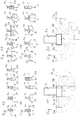
- a main hull 1 is provided with a superstructure 1 a, on which two arms 2 a, 2 b are mounted via pivot arms 3 a, 3 b.
- the main hull 1 can only consist of the structure of the mechanism and thus does not necessarily have a buoyancy function.
- the arms 2a, 2b can also be attached directly to the main hull 1.
- the arms 2a, 2b are articulated on the structure 1a via first pivot axes 4a, 4b, while the arms 2a, 2b are articulated on the pivot arms 3a, 3b via second pivot axes 5a, 5b.
- the movement of the one arm 2a is shown from a directly applied to the main hull 1 position in a laterally spaced from the main hull 1 position, ie the movement of the boom 2a corresponding to the double arrow 21, this is via a suitable sliding the first pivot axis 4a corresponding to the Double arrow 22 lowered and the pivot arm 3a pivoted accordingly.
- the boom 2a performs no pivoting movement in this movement itself.
- FIG. 1 two different modes of movement are shown on the right and left, however, which are usually carried out symmetrically in practice.
- Fig. 2 is an illustration of an embodiment analogous to Fig. 1 , wherein the difference of this embodiment to that of Fig. 1 It is that the second pivot axis 5a, 5b is not hinged on the inside of the arms 2a, 2b, but on the outside thereof.
- the pivot arms 3a, 3b are designed to be slightly longer.
- the movement shown on the left of the jib 2a corresponding to the double arrow 21 is largely analogous to the embodiment of Fig. 1 , However, the movement of the boom 2b to a position below the main hull 1 is solved differently.
- the boom 2 b is first moved downwardly with an inclined pivot arm 3 b corresponding to the double arrow 24, and then the pivot arm 3 b is pivoted in the clockwise direction so that the arm 2 b corresponding to the double arrow 26 moves to the left below into a position below the main body 1 emotional. In contrast to the variant of Fig. 1 In this movement, no pivoting of the boom 2b itself takes place.
- Fig. 3 In its basic structure corresponds largely to that of Fig. 1 , the arms 2a, 2b are arranged in their voltage applied to the main hull 1 position so that the second pivot axis 5a, 5b is inside.
- the one in the right half of Fig. 3 The movement shown is virtually identical to that in Fig. 1 illustrated movement.
- different is the pivoting of the boom 2a in its laterally arranged next to the main hull 1 position.
- a pivoting movement of the boom 2a in the counterclockwise direction executed (double arrow 27).
- Fig. 5 shows the three basic positions of the watercraft of this embodiment variant schematically.
- the two arms 2a, 2b are arranged laterally next to the main hull 1 at a distance from this.
- the arms 2a, 2b rest directly on the main hull 1, and in the third illustration, the arms 2a, 2b are positioned below the main hull 1 in the closed position.
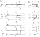
- the Fig. 6 to 11 show the variants of the Fig. 1 and Fig. 2 in the different positions and although in each case the left half of the figures shows the variant of Fig. 2 while the right half of the figures show the variant of Fig. 1 represents.
- FIGS. 6 and Fig. 7 show the position with lateral distance from the main hull 1 arranged arms 2a, 2b.
- FIGS. 8 and 9 show the boom 2a, 2b directly adjacent to the main hull 1. It is immediately apparent that the position of the pivot arms 3a, 3b is different, since in the embodiment of the left half of the second pivot axes 5a, 5b are externally mounted, in the right embodiment, however, inside.
- Fig. 10 shows the position of the arms 2a, 2b inserted below the main hull 1 with the left arm 2a and swung the right boom 2b, as before Fig. 1 and to Fig. 2 has been declared.
- Fig. 12 shows an embodiment of the invention with extended possibilities of movement. From the left half of Fig. 12 is the range of motion of the boom 2a with lowered first pivot axis 4a visible.
- the boom 2a can not only be brought into a position below the main hull 1, but also be moved further down, so that the boom 2a with respect to the main hull 1 has a distance.
- the pivot arm 3a can be pivoted from its horizontal position not only down but also upwards, so that the boom 2a can be brought into a position above the main hull 1.
- the first pivot axis 4b are moved by means of a sliding guide 7 also upwards, so that the range of movement of the boom 2b is further increased.
- the movement of the two pivot arms 3a, 3b must in the embodiment of Fig. 12 not necessarily symmetrical.
- the position of the pivot axis 4b along the slide 7 can be adjusted continuously.
- the diagram of Fig. 13 shows that the left arm 2a is lowered obliquely downward from the view of the main body 1, while the right arm 2b is raised to the same extent.
- the in Fig. 13 set position with inclined obliquely in the direction of clockwise main hull 1, which is particularly advantageous for cornering, for example. It is conceivable, for example, also a balancing a lateral rolling motion in the swell.
- Fig. 14 shows in four diagrams how a watercraft with capsized main hull 1 can be erected. First, the arms 2a, 2b are brought into the lower or upper end position from the view of the main hull 1 and then moved stepwise into the middle position. From top to bottom, the diagrams show the Fig. 14 the process of erecting the main hull 1.
- FIGS. 15 and 16 show in five diagrams or four diagrams the extended possibilities of execution according to Fig. 12 , This refers Fig. 15 on the basic execution of Fig. 1 and Fig. 16 on the basic execution of Fig. 2 ,
- a transformation of a trimaran can be achieved via a catamaran in a monohull, with all associated changes in driving behavior and characteristics.
- Fig. 15 shows a catamaran with reduced width and in the fourth position, the arms 2a, 2b are folded under the main hull 1 and moved down. This results in a particularly manoeuvrable but also unstable driving behavior.
- the fifth illustration shows the arms 2a, 2b below the main hull 1 but directly to this fitting.
- the third and the fourth presentation of Fig. 16 corresponds to the fourth and fifth representation of Fig. 15 ,
- Fig. 17 shows five positions of a variant in which both the main hull 1 and the arms 2a, 2b wings 6 are provided extendable. Not extended wings are not shown here for the sake of simplicity, which is justified insofar as the wings 6 are added in the retracted state in not visible recesses here.
- the first presentation of the Fig. 17 shows a position with a lateral distance next to the main hull 1 arranged arms 2a, 2b with each extended wings 6.
- the wing mode is thus functionally a catamaran.
- the second representation corresponds to the first representation with the difference that the main hull 1 is raised relative to the arms 2a, 2b. Again, wings 6 are extended only on the arms 2a, 2b.
- the first two representations refer not only to a watercraft in which wings 6 in the main hull 1 are provided, but are retracted, but also to a watercraft in which no wings are provided in the main hull 1.
- the third presentation of the Fig. 17 refers to a position corresponding to the first representation with the difference that also on the main hull 1 wings 6 are extended.
- the fourth representation corresponds to the second, but the wings 6 of the main hull 1 are further extended accordingly to take into account the increased position of the main hull 1.
- a wing 6 is extended only on the main hull 1, which is guided between the arms 2a, 2b.
- Fig. 18 largely corresponds to the Fig. 17 with the difference that this representation does not affect the variant of Fig. 15 but on the variant of Fig. 16 , each extended to the wings 6, relates.
- Fig. 19 shows two different modes of movement to achieve the same final state in a variant embodiment accordingly Fig. 1 ,
- the boom 2a is lowered by pivoting the swing arm 3a in the counterclockwise direction about the first pivot axis 4a.
- no movement takes place, so that the boom 2a is pivoted in the lower position ultimately by 90 ° relative to the upper position.
- the boom is moved during the pivoting movement in the manner of a parallelogram and does not change its angular position. Only when the pivot arm 3b is in its vertical end position, the boom 2b is moved by a pivoting movement about the second pivot axis 5b in its end position.
- the end position is identical for the arms 2a, 2b in both cases.
- Fig. 20 shows the pivoting movement of a variant according to Fig. 2 , In the left half finds a movement of the same type as in Fig. 19 instead of. In the right half of the movement of the boom 2b is again shown in the manner of a parallelogram, but not in the end position Pivoting movement is performed so that the arm 2b remains parallel to its initial position.
- FIGS. 21 and 22 show different simplified embodiments of a watercraft according to the invention in which the boom 2a, 2b with respect to the main hull 1 can only be pivoted.
- This pivotal movement takes place downwards, while in the embodiment of Fig. 22 the pivoting movement takes place upwards.
- Fig. 22 Of course, different structures 1b of the main hull 1 to adapt accordingly to allow this pivoting movement.
- Fig. 23 shows five different positions of a variant in which the arms 2a, 2b can be arranged in the form of a roof above the main hull 1.
- Fig. 24, Fig. 25, Fig. 26 and Fig. 27 show further pivoting and displacement movements of arms 2a, 2b with respect to the main hull 1.
- the pivot arm 3a has only a very short length or omitted (length ⁇ 0).
- FIGS. 28 and 29 show various embodiments as the arms 2a, 2b can be arranged above the main hull 1, wherein in Fig. 29 a roof-shaped configuration of the boom 2a, 2b is achieved, which can be used for example as a rollover cage.
- the arms 10a, 10b are each articulated on a mechanism which consists of two interconnected pivoting arms 3a, 3c and 3b, 3d.
- the cantilevers 10a, 10b may be pivotally mounted about a longitudinal axis on the outer pivot arms 3c, 3d to further increase variability.
- the arms 10a, 10b are arranged under the main hull 1a, which serves here only as a support for structures not shown and itself is not necessarily buoyant.
- the two arms 10a, 10b form in this point a common compact shell, ie they form on their outer sides a boat shape and lie with their inner sides largely closely to each other. This is a typical high-speed ride where lateral stabilization is dynamic.
- FIG. 33 is raised in the main hull 1a.
- Fig. 34 is shown a position for cornering with inclined main hull 1a.
- Swivel arms 2a, 3a carry the wings 6, which are thus adjustable in height, since the pivot arms 2a, 3a about pivot points 22 and 23 are pivotable.
- the FIGS. 35 and 36 show the pivot arms 2a, 3a respectively in a front, a contracted position, in which the wings 6 are received in their recesses and in the extended position, in which the wings 6 at a distance below the arms 10a, 10b are arranged.
- 20 and 21 further recesses are indicated, which are provided in the arms 10 a, 10 b inside to in the position of Fig. 30 to allow passage of the pivot arms 2a, 3a through the otherwise directly adjoining arms 10a, 10b.
Landscapes
- Physics & Mathematics (AREA)
- Fluid Mechanics (AREA)
- Chemical & Material Sciences (AREA)
- Engineering & Computer Science (AREA)
- Combustion & Propulsion (AREA)
- Mechanical Engineering (AREA)
- Ocean & Marine Engineering (AREA)
- Vehicle Cleaning, Maintenance, Repair, Refitting, And Outriggers (AREA)
- Jib Cranes (AREA)
Description
- Die vorliegende Erfindung betrifft ein Wasserfahrzeug mit einem Hauptrumpf und mindestens einem Ausleger, der verstellbar am Hauptrumpf befestigt ist.
- Es ist bekannt, Wasserfahrzeuge mit Auslegern auszustatten, die seitlich neben dem Hauptrumpf angeordnet sind. Dadurch kann die Stabilität wesentlich erhöht werden und ein Kentern wird praktisch unmöglich gemacht.
- Es ist jedoch nicht für alle Einsatzbereiche erwünscht, Ausleger zu verwenden, da diese die dynamischen Eigenschaften des Wasserfahrzeugs beeinflussen.
- Aus der
US 5,373,799 A ist ein Wasserfahrzeug bekannt, das bewegliche Ausleger aufweist. Dadurch kann eine Platzeinsparung bei der Aufbewahrung erreicht werden. Es können die Fahreigenschaften aber nicht grundsätzlich verändert werden. -
US 2,678,018 undUS 4,337,543 offenbaren in Höhe verstellbare unter dem Rumpf anordenbare Auslegerboote. - Aufgabe der vorliegenden Erfindung ist es, eine Lösung anzugeben, die eine wesentlich weiter gehende Variabilität ermöglicht als bisher bekannte Konstruktionen. Insbesondere soll ein extrem sportliches und wendiges Verhalten eines Rennboots mit der Robustheit eines Ausleger-Boots vereint werden.
- Erfindungsgemäß ist vorgesehen, dass der Ausleger in der Höhe verstellbar angeordnet ist. Die Höhenverstellung kann gegebenenfalls zusätzlich zu einer Verstellung in der Breite vorgesehen sein. Auf diese Weise ist es möglich, die Fahreigenschaften des Wasserfahrzeugs wesentlich zu verändern und zu beeinflussen.
- Mechanisch besonders günstig ist es, wenn der Ausleger schwenkbar am Hauptrumpf angeordnet ist. Dadurch kann ein besonders großer Bewegungsbereich mit einfachen Mitteln realisiert werden. Vorzugsweise ist die Schwenkeinrichtung als Parallelogrammführung ausgeführt.
- Eine besonders bevorzugte Ausführungsvariante der Erfindung ist derart ausgebildet, dass der Ausleger aus einer seitlich neben dem Hauptrumpf angeordneten Stellung in eine unterhalb des Hauptrumpfs angeordneten Stellung bewegbar ist.
- Durch die vorliegende Erfindung ist es möglich, neben der Charakteristik eines Ausleger-Boots auch eine grundsätzlich wenig stabile Rennboot-Charakteristik darzustellen, die extreme Seitenlagen und günstiges Fahrverhalten bei höchsten Geschwindigkeiten bietet. Es ist vorgesehen, dass zumindest zwei Ausleger in der unterhalb des Hauptrumpfs angeordneten Stellung unmittelbar aneinander liegen und vorzugsweise eine gemeinsame kompakte Hülle bilden. Dadurch können auch in dieser Stellung der Ausleger besonders günstige hydrodynamische Eigenschaften erreicht werden. Insbesondere können Wendigkeit und Fahrverhalten gesteigert werden.
- Eine noch größere Erweiterung des Anwendungsspektrums kann erzielt werden, wenn zumindest ein Ausleger aus einer seitlich neben dem Hauptrumpf angeordneten Stellung in eine oberhalb des Hauptrumpfs angeordnete Stellung bewegbar ist.
- Es ist auch günstig, wenn zumindest zwei Ausleger unabhängig voneinander schwenkbar angeordnet sind. Auf diese Weise kann beispielsweise ein gekentertes Boot nur durch geeignete Bewegung der Ausleger wieder aufgerichtet werden. Es können aber auch Vorteile bei der Kurvenfahrt erzielt werden.
- Eine besonders sportliche Konfiguration kann erreicht werden, wenn zumindest zwei Ausleger um jeweils eine Schwenkachse in eine im Abstand unterhalb des Hauptrumpfs angeordneten Stellung schwenkbar sind.
- Kritische Situationen mangelnder Stabilität können beispielsweise dadurch vermieden werden, dass eine Einrichtung zum automatischen Bewegen des Auslegers vorgesehen ist, die unterhalb einer vorbestimmten Mindestgeschwindigkeit des Wasserfahrzeugs den Ausleger in die seitlich neben dem Hauptrumpf angeordnete Stellung bringt. Analog kann eine Automatik bei höheren Geschwindigkeiten die Ausleger unter den Hauptrumpf bewegen.
- Vorzugsweise sind an zumindest einem Ausleger Tragflächen angeordnet. Es ist bekannt, Wasserfahrzeuge mit Tragflächen auszustatten, die es ermöglichen, ab einer bestimmten Mindestgeschwindigkeit den Rumpf aus dem Wasser zu heben. Dadurch kann der Strömungswiderstand deutlich verringert werden und es können höhere Geschwindigkeiten bei geringerem Treibstoffverbrauch erzielt werden. Außerdem kann ein weitgehend vom Wellengang unbeeinflusstes Fahrverhalten den Komfort wesentlich verbessern.
- Die Tragflächen sind üblicherweise an Auslegern in einem ausreichenden Abstand unter dem Rumpf befestigt, um so die erforderlich Höhe im Tragflächen-Betrieb zu erreichen. Dies bedingt aber im Stillstand oder bei niedrigen Fahrgeschwindigkeiten einen großen Tiefgang mit der Gefahr der Beschädigung der Tragflächen durch Hindernisse unter Wasser.
- Dies führt auch dazu, dass Tragflächenboote nicht im Flachwasser bzw. in Ufernähe betrieben werden können. Darüber hinaus sind die empfindlichen Tragflächen beim Transport des Bootes sperrig und können daher leicht beschädigt werden, wenn sie nicht demontiert werden.
- Insbesondere ist daher im Rumpf eine Ausnehmung vorgesehen, die die Tragfläche in der im Bereich des Rumpfs gelegenen Stellung aufnimmt.
- Durch die vorgeschlagene Lösung werden die Störungen bei eingefahrener Tragfläche, d.h. im Verdrängungsbetrieb minimiert. Das Wasserfahrzeug kann daher auch im Flachwasser betrieben werden und ohne Gefahr von Beschädigungen auf einen Strand auffahren.
- Konstruktiv besonders vorteilhaft ist es, wenn die Tragfläche auf einem teleskopisch ausfahrbaren Arm angeordnet ist. Dadurch kann ein großer Verstellbereich erzielt werden, wobei die Tragfläche auch in Zwischenstellungen optimal situiert ist.
- Besonders günstig ist es, wenn am teleskopisch ausfahrbaren Arm ein Antriebselement, beispielsweise ein Jet-Ski-Antrieb angeordnet ist. Dadurch wird nicht nur eine in allen Stellungen der Tragfläche optimale Position des Antriebs erreicht, es erfolgt auch die Einleitung der Antriebskraft direkt an dem dem Strömungswiderstand ausgesetzten Bauteil, so dass die Materialbeanspruchung verringert wird.
- Vorzugsweise ist vorgesehen, dass die Ausnehmung das Antriebselement aufnimmt und Strömungskanäle für Zu- und Abströmung aufweist. Auf diese Weise kann das Antriebselement auch dann benutzt werden, wenn die Tragfläche ganz eingefahren ist, um einen minimalen Tiefgang zu erreichen.
- In der Folge wird die vorliegende Erfindung durch die in den Figuren dargestellten Ausführungsvarianten näher erläutert Es zeigen schematisch:
- Fig. 1
- bis
Fig. 4 die Kinematik unterschiedlicher Ausführungsvarianten der Erfindung in der Form eines schematischen Querschnitts; - Fig. 5
- drei Diagramme zur grundsätzlichen Erläuterung der Erfindung;
- Fig. 6,
-
Fig. 8 und Fig. 10 schematische Ansichten einer Ausführungsvariante der Erfindung in verschiedenen Stellungen von oben; - Fig. 7,
-
Fig. 9 und Fig. 11 die Stellungen derFig. 6, Fig. 8 und Fig. 10 in einer Ansicht von hinten; - Fig. 12
- ein weiteres schematisches Diagramm einer Ausführungsvariante der Erfindung;
- Fig. 13
- ein Diagramm zur Erläuterung der Nutzung der Erfindung;
- Fig. 14
- vier Diagramme zur Erläuterung der Nutzung der Erfindung;
- Fig. 15
- fünf Diagramme zur Erklärung der Variabilität;
- Fig. 16
- vier Diagramme einer alternativen Ausführungsvariante in einer der Darstellung entsprechend
Fig. 15 ; - Fig. 17
- fünf Diagramme zur Erläuterung der möglichen Stellungen einer weiteren Ausführungsvariante der Erfindung;
- Fig. 18
- fünf Diagramme zur Erläuterung einer weiteren alternativen Ausführungsvariante der Erfindung;
- Fig. 19
- und
Fig. 20 weitere Diagramme zur Erklärung der Bewegungsmöglichkeiten; - Fig. 21
- drei Diagramme einer weiteren Ausführungsvariante;
- Fig. 22
- drei Diagramme einer alternativen Ausführungsvariante;
- Fig. 23
- fünf Diagramme einer weiteren alternativen Ausführungsvariante;
- Fig. 24
- bis
Fig. 27 jeweils ein Diagramm zur Erklärung weiterer Ausführungsvarianten; - Fig. 28,
-
Fig. 29 weitere Ausführungsvarianten der Erfindung jeweils in einer Ansicht von vorne; und - Fig. 30
- bis
Fig. 36 eine weitere Ausführungsvariante der Erfindung in verschiedenen Stellungen. - In der Ausführungsvariante von
Fig. 1 ist ein Hauptrumpf 1 mit einem Aufbau 1a vorgesehen, an dem über Schwenkarme 3a, 3b zwei Ausleger 2a, 2b angebracht sind. Im Grenzfall kann jedoch der Hauptrumpf 1 auch nur aus dem Aufbau der Mechanik bestehen und muss damit nicht zwingend eine Auftriebsfunktion besitzen. Die Ausleger 2a, 2b können aber auch direkt am Hauptrumpf 1 befestigt sein. Die Ausleger 2a, 2b sind über erste Schwenkachsen 4a, 4b am Aufbau 1a angelenkt, während die Ausleger 2a, 2b über zweite Schwenkachsen 5a, 5b an den Schwenkarmen 3a, 3b angelenkt sind. In der linken Hälfte der Darstellung vonFig. 1 ist die Bewegung des einen Auslegers 2a aus einer direkt am Hauptrumpf 1 anliegenden Stellung in eine seitlich im Abstand vom Hauptrumpf 1 angeordnete Stellung dargestellt, d.h. die Bewegung des Auslegers 2a entsprechend dem Doppelpfeil 21, dabei wird über eine geeignete Gleitführung die erste Schwenkachse 4a entsprechend dem Doppelpfeil 22 abgesenkt und der Schwenkarm 3a entsprechend verschwenkt. Der Ausleger 2a führt bei dieser Bewegung selbst keine Schwenkbewegung aus. - In der rechten Hälfte der Darstellung von
Fig. 1 ist gezeigt, dass zunächst der rechte Ausleger 2b durch eine Absenkung der ersten Schwenkachse 4b entsprechend dem Doppelpfeil 23 nach unten bewegt wird (Doppelpfeil 24). Danach erfolgt eine Schwenkbewegung des Auslegers 2b entsprechend dem Doppelpfeil 25, so dass der Ausleger 2b unterhalb des Hauptrumpfs 1 zu liegen kommt. - Es ist ersichtlich, dass in
Fig. 1 zwei unterschiedliche Bewegungsmodi rechts bzw. links dargestellt sind, die jedoch in der Praxis in der Regel symmetrisch ausgeführt werden. -
Fig. 2 ist eine Darstellung einer Ausführungsvariante analog zuFig. 1 , wobei der Unterschied dieser Ausführungsvariante zu der vonFig. 1 darin besteht, dass die zweite Schwenkachse 5a, 5b nicht innen an den Auslegern 2a, 2b, sondern an deren Außenseite angelenkt ist. Die Schwenkarme 3a, 3b sind entsprechend etwas länger ausgeführt. Die links dargestellte Bewegung des Auslegers 2a entsprechend dem Doppelpfeil 21 erfolgt weitgehend analog zu der Ausführungsvariante vonFig. 1 . Die Bewegung des Auslegers 2b in eine Stellung unterhalb des Hauptrumpfs 1 ist jedoch unterschiedlich gelöst. Der Ausleger 2b wird zunächst bei schräg gestelltem Schwenkarm 3b entsprechend dem Doppelpfeil 24 nach unten bewegt und danach wird der Schwenkarm 3b in der Richtung des Uhrzeigersinns verschwenkt, so dass sich der Ausleger 2b entsprechend dem Doppelpfeil 26 nach links unterhalb in eine Stellung unterhalb des Hauptrumpfs 1 bewegt. Im Gegensatz zu der Ausführungsvariante vonFig. 1 findet bei dieser Bewegung keine Verschwenkung des Auslegers 2b selbst statt. - Die Ausführungsvariante von
Fig. 3 entspricht in ihrem grundsätzlichen Aufbau weitgehend der vonFig. 1 , insbesondere sind die Ausleger 2a, 2b in ihrer am Hauptrumpf 1 anliegenden Stellung so angeordnet, dass sich die zweite Schwenkachse 5a, 5b innen befindet. Die in der rechten Hälfte vonFig. 3 dargestellte Bewegung ist praktisch identisch zu der inFig. 1 dargestellten Bewegung. Unterschiedlich ist jedoch die Verschwenkung des Auslegers 2a in seine seitlich neben den Hauptrumpf 1 angeordnete Stellung. Hierbei wird gleichzeitig mit der Verschwenkung des Schwenkarms 3a und der Bewegung des Auslegers 2a entsprechend des Doppelpfeils 21 weg vom Hauptrumpf 1 eine Schwenkbewegung des Auslegers 2a in Richtung entgegengesetzt zum Uhrzeigersinn ausgeführt (Doppelpfeil 27). - Bei der Ausführungsvariante von
Fig. 4 , die weitestgehend der vonFig. 2 entspricht, erfolgt die in der linken Hälfte dargestellte Bewegung des Auslegers 2a in seine seitlich im Abstand vom Hauptrumpf 1 angeordnete Stellung ähnlich zu der Bewegung vonFig. 2 . Jedoch wird der Schwenkarm 3a durch die Montage der Schwenkachse 5a an einer Gleitführung 7 komplett an den Aufbau 1a analog zuFig. 1 angelegt. Unterschiedlich ist zusätzlich die rechts dargestellte Bewegung des Auslegers 2b in seine Stellung unterhalb des Hauptrumpfs 1. Zunächst wird der Schwenkarm 3b entsprechend dem Doppelpfeil 23 abgesenkt und danach wird der Ausleger 2b mittels der Gleitführung 7 unter den Hauptrumpf 1 verschoben (Doppelpfeil 28). -
Fig. 5 zeigt die drei grundsätzlichen Stellungen des erfindungsgemäßen Wasserfahrzeugs dieser Ausführungsvariante schematisch. In der oberen Stellung sind die beiden Ausleger 2a, 2b seitlich neben den Hauptrumpf 1 im Abstand von diesem angeordnet. In der zweiten Darstellung darunter liegen die Ausleger 2a, 2b direkt am Hauptrumpf 1 an und in der dritten Darstellung sind die Ausleger 2a, 2b in geschlossener Stellung unterhalb des Hauptrumpfs 1 positioniert. - Die
Fig. 6 bis 11 zeigen die Ausführungsvarianten derFig. 1 und Fig. 2 in den verschiedenen Stellungen und zwar zeigt jeweils die linke Hälfte der Figuren die Ausführungsvariante vonFig. 2 , während die rechte Hälfte der Figuren die Ausführungsvariante vonFig. 1 darstellt. - Die
Fig. 6 und Fig. 7 zeigen die Stellung mit seitlichem Abstand vom Hauptrumpf 1 angeordneten Auslegern 2a, 2b.Fig. 8 und Fig. 9 zeigen die Ausleger 2a, 2b direkt am Hauptrumpf 1 anliegend. Es ist unmittelbar ersichtlich, dass die Stellung der Schwenkarme 3a, 3b unterschiedlich ist, da in der Ausführungsvariante der linken Hälfte die zweiten Schwenkachsen 5a, 5b außen, bei der rechten Ausführungsvariante jedoch innen angebracht sind.Fig. 10 zeigt die Stellung der Ausleger 2a, 2b unterhalb des Hauptrumpfs 1 mit dem linken Ausleger 2a eingeschoben und dem rechten Ausleger 2b eingeschwenkt, so wie dies zuvor zuFig. 1 und zuFig. 2 erklärt worden ist. -
Fig. 12 zeigt eine Ausführungsvariante der Erfindung mit erweiterten Möglichkeiten der Bewegung. Aus der linken Hälfte vonFig. 12 ist der Bewegungsspielraum des Auslegers 2a bei abgesenkter erster Schwenkachse 4a ersichtlich. Der Ausleger 2a kann nicht nur in eine Stellung unterhalb des Hauptrumpfs 1 gebracht werden, sondern auch weiter nach unten verschoben werden, so dass der Ausleger 2a gegenüber dem Hauptrumpf 1 einen Abstand aufweist. Der Schwenkarm 3a kann von seiner waagrechten Stellung aus nicht nur nach unten sondern auch nach oben verschwenkt werden, so dass der Ausleger 2a in eine Stellung oberhalb des Hauptrumpfs 1 gebracht werden kann. Zusätzlich dazu kann - so wie das in der rechten Hälfte derFig. 12 dargestellt ist - die erste Schwenkachse 4b mittels einer Gleitführung 7 auch nach oben verschoben werden, so dass der Bewegungsbereich des Auslegers 2b noch weiter gesteigert ist. - Die Bewegung der beiden Schwenkarme 3a, 3b muss bei der Ausführungsvariante von
Fig. 12 nicht zwangsläufig symmetrisch gestaltet werden. Insbesondere kann die Position der Schwenkachse 4b entlang der Gleitführung 7 stufenlos eingestellt werden. Das Diagramm vonFig. 13 zeigt, dass der linke Ausleger 2a aus sicht des Hauptrumpfs 1 schräg nach unten abgesenkt ist, während der rechte Ausleger 2b in gleichem Ausmaß angehoben ist. Auf einer Wasserfläche wird sich jedoch die inFig. 13 dargestellte Stellung mit schräg in Richtung des Uhrzeigersinns geneigtem Hauptrumpf 1 einstellen, die beispielsweise für Kurvenfahrten besonders vorteilhaft ist. Denkbar ist z.B. ebenfalls ein Austarieren einer seitlichen Rollbewegung im Wellengang. -
Fig. 14 zeigt in vier Diagrammen wie ein Wasserfahrzeug mit gekentertem Hauptrumpf 1 aufgerichtet werden kann. Zunächst werden die Ausleger 2a, 2b in die aus Sicht des Hauptrumpfs 1 untere bzw. obere Endstellung gebracht und danach schrittweise in die mittlere Stellung bewegt. Von oben nach unten zeigen die Diagramme derFig. 14 den Vorgang des Aufrichtens des Hauptrumpfs 1. -
Fig. 15 und Fig. 16 zeigen in fünf Diagrammen bzw. vier Diagrammen die erweiterten Möglichkeiten einer Ausführung gemäßFig. 12 . Dabei bezieht sichFig. 15 auf die grundsätzliche Ausführung vonFig. 1 undFig. 16 auf die grundsätzliche Ausführung vonFig. 2 . Durch diese Varianten kann insbesondere eine Transformation eines Trimarans über einen Katamaran in einen Monohull erreicht werden, mit allen zugehörigen Änderungen des Fahrverhaltens und der Eigenschaften. - Neben der links dargestellten Standardauslegerstellung mit Auslegern 2a, 2b seitlich im Abstand des Hauptrumpfs 1 kann in der zweiten Darstellung einen Katamaran mit größerer Breite dargestellt werden. Die dritte Darstellung von
Fig. 15 zeigt einen Katamaran mit verringerter Breite und in der vierten Stellung sind die Ausleger 2a, 2b unter den Hauptrumpf 1 eingeklappt und nach unten verschoben. Dadurch ergibt sich ein besonders wendiges aber auch instabiles Fahrverhalten. Die fünfte Darstellung zeigt die Ausleger 2a, 2b unterhalb des Hauptrumpfs 1 jedoch direkt an diesem anliegend. Die dritte und die vierte Darstellung vonFig. 16 entspricht der vierten bzw. fünften Darstellung vonFig. 15 . -
Fig. 17 zeigt fünf Stellungen einer Ausführungsvariante bei der sowohl am Hauptrumpf 1 als auch an den Auslegern 2a, 2b Tragflächen 6 ausfahrbar vorgesehen sind. Nicht ausgefahrene Tragflächen sind hier zur Vereinfachung nicht dargestellt, was insofern gerechtfertigt ist, als die Tragflächen 6 in eingefahrenem Zustand in hier nicht sichtbaren Ausnehmungen aufgenommen sind. - Die erste Darstellung der
Fig. 17 zeigt eine Stellung mit seitlichem Abstand neben den Hauptrumpf 1 angeordneten Auslegern 2a, 2b mit jeweils ausgefahrenen Tragflächen 6. Im Tragflächenmodus handelt es sich somit funktionell um einen Katamaran. Die zweite Darstellung entspricht der ersten Darstellung mit dem Unterschied, dass der Hauptrumpf 1 gegenüber den Auslegern 2a, 2b angehoben ist. Auch hier sind Tragflächen 6 nur an den Auslegern 2a, 2b ausgefahren. - Es ist selbstverständlich, dass die ersten beiden Darstellungen sich nicht nur auf ein Wasserfahrzeug beziehen, bei dem Tragflächen 6 im Hauptrumpf 1 zwar vorgesehen jedoch eingefahren sind, sondern auch auf ein Wasserfahrzeug, bei dem im Hauptrumpf 1 keine Tragflächen vorgesehen sind.
- Die dritte Darstellung der
Fig. 17 bezieht sich auf eine Stellung entsprechend der ersten Darstellung mit dem Unterschied, dass auch am Hauptrumpf 1 Tragflächen 6 ausgefahren sind. Die vierte Darstellung entspricht der zweiten, wobei jedoch die Tragflächen 6 des Hauptrumpfs 1 entsprechend weiter ausgefahren sind, um der erhöhten Stellung des Hauptrumpfs 1 Rechnung zu tragen. Bei der fünften Darstellung ist nur am Hauptrumpf 1 eine Tragfläche 6 ausgefahren, die zwischen den Auslegern 2a, 2b hindurch geführt ist. -
Fig. 18 entspricht weitestgehend derFig. 17 mit dem Unterschied, dass sich diese Darstellung nicht auf die Ausführungsvariante vonFig. 15 sondern auf die Ausführungsvariante vonFig. 16 , jeweils erweitert um die Tragflächen 6, bezieht. -
Fig. 19 zeigt zwei unterschiedliche Bewegungsmodi zur Erreichung des gleichen Endzustands bei einer Ausführungsvariante entsprechendFig. 1 . In der linken Hälfte der Darstellung vonFig. 19 wird der Ausleger 2a abgesenkt, indem der Schwenkarm 3a in der Richtung gegen den Uhrzeigersinn um die erste Schwenkachse 4a verschwenkt wird. An der zweiten Schwenkachse 5a findet keine Bewegung statt, so dass der Ausleger 2a in der unteren Stellung letztlich um 90° gegenüber der oberen Stellung verschwenkt ist. In der rechten Hälfte derFig. 19 wird der Ausleger während der Schwenkbewegung in der Art einer Parallelogrammführung bewegt und ändert seine Winkellage nicht. Erst wenn sich der Schwenkarm 3b in seiner senkrechten Endstellung befindet, wird der Ausleger 2b durch eine Schwenkbewegung um die zweite Schwenkachse 5b in seine Endstellung bewegt. Die Endstellung ist in beiden Fällen für die Ausleger 2a, 2b identisch. -
Fig. 20 zeigt die Schwenkbewegung einer Ausführungsvariante gemäßFig. 2 . In der linken Hälfte findet eine Bewegung gleichen Typs wie inFig. 19 statt. In der rechten Hälfte ist die Bewegung des Auslegers 2b wiederum in der Art einer Parallelogrammführung dargestellt, wobei jedoch in der Endstellung nicht die Schwenkbewegung durchgeführt wird, so dass der Ausleger 2b parallel zu seiner Anfangsstellung verbleibt. -
Fig. 21 und Fig. 22 zeigen unterschiedliche vereinfachte Ausführungsvarianten eines erfindungsgemäßen Wasserfahrzeugs bei denen die Ausleger 2a, 2b in Bezug auf den Hauptrumpf 1 nur verschwenkt werden können. Bei der Ausführungsvariante vonFig. 21 findet diese Schwenkbewegung nach unten statt, während bei der Ausführungsvariante vonFig. 22 die Schwenkbewegung nach oben stattfindet. BeiFig. 22 sind selbstverständlich verschiedene Aufbauten 1b des Hauptrumpfs 1 entsprechend anzupassen um diese Schwenkbewegung zu ermöglichen.Fig. 23 zeigt fünf verschiedene Stellungen einer Ausführungsvariante, bei der die Ausleger 2a, 2b in Form eines Dachs oberhalb des Hauptrumpfs 1 angeordnet werden können. -
Fig. 24, Fig. 25, Fig. 26 und Fig. 27 zeigen weitere Schwenk- und Verschiebebewegungen von Auslegern 2a, 2b in Bezug auf den Hauptrumpf 1. Dabei besitzt der Schwenkarm 3a nur eine sehr kurze Länge bzw. entfällt (Länge → 0). -
Fig. 28 und Fig. 29 zeigen verschiedene Ausführungsvarianten wie die Ausleger 2a, 2b oberhalb des Hauptrumpfs 1 angeordnet werden können, wobei inFig. 29 eine dachförmige Konfiguration der Ausleger 2a, 2b erreicht wird, die z.B. auch als Überschlagskäfig benutzt werden kann. - Bei der Ausführungsvariante der
Fig. 30 bis Fig. 34 sind die Ausleger 10a, 10b jeweils auf einem Mechanismus angelenkt, der aus zwei miteinander verbundenen Schwenkarmen 3a, 3c bzw. 3b, 3d besteht. Die Ausleger 10a, 10b können um eine Längsachse schwenkbar an den äußeren Schwenkarmen 3c, 3d befstigt sein, um die Variabilität weiter zu erhöhen. - In
Fig. 30 sind die Ausleger 10a, 10b unter dem Hauptrumpf 1a angeordnet, der hier nur als Träger für nicht dargestellte Aufbauten dient und selbst nicht notwendigerweise schwimmfähig ist. Die beiden Ausleger 10a, 10b bilden in dieser Stelle eine gemeinsame kompakte Hülle, d.h. sie bilden an ihren Außenseiten eine Bootsform und liegen mit ihren Innenseiten weitgehend eng aneinander. Dies ist eine typische Stellung für Hochgeschwindigkeitsfahrt, bei der die seitliche Stabilisierung dynamisch erfolgt. - In der Stellung von
Fig. 31 sind die Ausleger 10a, 10b seitlich unter dem Hauptrumpf 1a in einem Abstand angeordnet, wodurch sich eine inhärent stabile Lage ergibt. - Eine weitere Verschiebung der Ausleger 10a, 10b nach außen führt zu der Stellung gemäß
Fig. 32 , bei der die Schwenkarme 3a, 3c bzw. 3b, 3d eine gestreckte Lage einnehmen. - Eine weiter Variationsmöglichkeit ist in der
Fig. 33 dargestellt, in der Hauptrumpf 1a angehoben ist. InFig. 34 ist eine Stellung für die Kurvenfahrt mit geneigtem Hauptrumpf 1a gezeigt. - In den
Fig. 35 und Fig. 36 ist ein anderer Aspekt dieser Ausführungsvariante erklärt. Schwenkarme 2a, 3a tragen die Tragflächen 6, die somit höhenverstellbar sind, da die Schwenkarme 2a, 3a um Drehpunkte 22 bzw. 23 schwenkbar sind. DieFig. 35 und Fig. 36 zeigen die Schwenkarme 2a, 3a jeweils in einer vorderen, einegzogenen Stellung, in der die Tragflächen 6 in ihren Ausnehmungen aufgenommen sind und in der ausgefahrenen Stellung, in der die Tragflächen 6 im Abstand unter den Auslegern 10a, 10b angeordnet sind. Mit 20 und 21 sind weitere Ausnehmungen angedeutet, die in den Auslegern 10a, 10b innen vorgesehen sind, um in der Stellung vonFig. 30 ein Hindurchtreten der Schwenkarme 2a, 3a durch die ansonsten unmittelbar aneinanderliegenden Ausleger 10a, 10b zu ermöglichen.
Claims (16)
- Wasserfahrzeug mit einem Hauptrumpf (1; 1a) und mit zumindest zwei in der Höhe verstellbar am Hauptrumpf (1; 1a) befestigten Auslegern (2a, 2b), die in eine unterhalb des Hauptrumpfs (1; 1a) angeordnete Stellung bringbar sind, dadurch gekennzeichnet, dass die Ausleger (2a, 2b) in einer unterhalb des Hauptrumpfs (1; 1a) angeordneten Stellung unmittelbar aneinander liegen und eine gemeinsame kompakte Hülle bilden, wobei sie an ihren Außenseiten eine Bootsform bilden und mit ihren Innenseiten weitgehend eng aneinander liegen.
- Wasserfahrzeug nach Anspruch 1, dadurch gekennzeichnet, dass die Ausleger (2a, 2b) in zumindest einer Stellung entlang einer Ebene, vorzugsweise entlang der Medianebene des Wasserfahrzeugs spaltfrei aneinander liegen.
- Wasserfahrzeug nach Anspruch 1, dadurch gekennzeichnet, dass die Ausleger (2a, 2b) schwenkbar am Hauptrumpf (1; 1a) angeordnet sind.
- Wasserfahrzeug nach einem der Ansprüche 1 oder 2, dadurch gekennzeichnet, dass zumindest ein Ausleger (2a, 2b) über einen mindestens zwei Schwenkarme (3a, 3c; 3b, 3d) aufweisenden Mechanismus am Hauptrumpf (1; 1a) angeordnet ist.
- Wasserfahrzeug nach einem der Ansprüche 1 bis 3, dadurch gekennzeichnet, dass zumindest zwei Ausleger (2a, 2b) unabhängig voneinander schwenkbar angeordnet sind.
- Wasserfahrzeug nach einem der Ansprüche 1 bis 5, dadurch gekennzeichnet, dass zumindest ein Ausleger (2a, 2b) beweglich an einem Schwenkarm (3a, 3c; 3b, 3d) angebracht ist.
- Wasserfahrzeug nach Anspruch 6, dadurch gekennzeichnet, dass der Ausleger (2a, 2b) höhenverstellbar und schwenkbar am Schwenkarm (3a, 3b) angebracht ist.
- Wasserfahrzeug nach einem der Ansprüche 6 oder 7, dadurch gekennzeichnet, dass der Schwenkarm (3a, 3b) höhenverstellbar am Wasserfahrzeug angelenkt ist.
- Wasserfahrzeug nach einem der Ansprüche 1 bis 8, dadurch gekennzeichnet, dass eine Schwenkeinrichtung zur Bewegung des Auslegers (2a, 2b) vorgesehen ist, die als Parallelogrammführung ausgebildet ist.
- Wasserfahrzeug nach einem der Ansprüche 1 bis 9, dadurch gekennzeichnet, dass an zumindest einem Ausleger (2a, 2b) Tragflächen (6) angeordnet sind.
- Wasserfahrzeug nach einem der Ansprüche 1 bis 10, dadurch gekennzeichnet, dass am Hauptrumpf (1; 1a) Tragflächen (6) angeordnet sind.
- Wasserfahrzeug nach einem der Ansprüche 10 oder 11, dadurch gekennzeichnet, dass im Hauptrumpf (1; 1a) bzw. im Ausleger (2a, 2b) eine Ausnehmung (20, 21) vorgesehen ist, die die Tragfläche (6) in der im Bereich des Hauptrumpf (1; 1a) bzw. im Ausleger (2a, 2b) gelegenen Stellung aufnimmt.
- Wasserfahrzeug nach einem der Ansprüche 10 bis 12, dadurch gekennzeichnet, dass zumindest eine Tragfläche (6) teleskopisch ausfahrbar oder ausschwenkbar ausgeführt ist.
- Wasserfahrzeug nach Anspruch 13, dadurch gekennzeichnet, dass die Tragfläche (6) über eine Parallelogrammführung schwenkbar ist.
- Wasserfahrzeug nach einem der Ansprüche 1 bis 14, dadurch gekennzeichnet, dass eine Einrichtung zum automatischen Bewegen des Auslegers (2a, 2b) vorgesehen ist, die unterhalb einer vorbestimmten Mindestgeschwindigkeit des Wasserfahrzeugs den Ausleger (2a, 2b) in die seitlich neben dem Hauptrumpf (1; 1a) angeordneten Stellung bringt und vorzugsweise oberhalb der Mindestgeschwindigkeit des Wasserfahrzeugs den Ausleger (2a, 2b) in die unterhalb des Hauptrumpfs (1; 1a) angeordnete Stellung bringt.
- Wasserfahrzeug nach einem der Ansprüche 1 bis 15, dadurch gekennzeichnet, dass zumindest ein Ausleger (2a, 2b) aus einer seitlich neben dem Hauptrumpf (1; 1a) angeordneten Stellung in eine oberhalb des Hauptrumpfs (1; 1a) angeordnete Stellung bewegbar ist.
Applications Claiming Priority (2)
| Application Number | Priority Date | Filing Date | Title |
|---|---|---|---|
| ATA978/2010A AT509948B1 (de) | 2010-06-14 | 2010-06-14 | Wasserfahrzeug |
| PCT/EP2011/059714 WO2011157660A1 (de) | 2010-06-14 | 2011-06-10 | Trimaran mit schwenkbaren ausleger |
Publications (2)
| Publication Number | Publication Date |
|---|---|
| EP2580113A1 EP2580113A1 (de) | 2013-04-17 |
| EP2580113B1 true EP2580113B1 (de) | 2018-02-07 |
Family
ID=44514644
Family Applications (1)
| Application Number | Title | Priority Date | Filing Date |
|---|---|---|---|
| EP11728797.9A Active EP2580113B1 (de) | 2010-06-14 | 2011-06-10 | Trimaran mit schwenkbarem ausleger |
Country Status (6)
| Country | Link |
|---|---|
| US (1) | US10173750B2 (de) |
| EP (1) | EP2580113B1 (de) |
| AT (1) | AT509948B1 (de) |
| CA (1) | CA2802086C (de) |
| RU (1) | RU2554729C2 (de) |
| WO (1) | WO2011157660A1 (de) |
Families Citing this family (6)
| Publication number | Priority date | Publication date | Assignee | Title |
|---|---|---|---|---|
| US9016220B2 (en) * | 2012-09-17 | 2015-04-28 | Clearpath Robotics, Inc. | Variable geometry water vessel |
| RU2610161C1 (ru) * | 2016-01-11 | 2017-02-08 | Николай Петрович Дядченко | Тримаран |
| RU2653983C1 (ru) * | 2017-05-02 | 2018-05-15 | Владимир Станиславович Тарадонов | Надводно-подводный аппарат с изменяемой геометрией формы корпуса |
| GB201710201D0 (en) * | 2017-06-16 | 2017-08-09 | Wavefoil As | Retractable foil mechanism |
| USD1008924S1 (en) * | 2020-10-23 | 2023-12-26 | Neil Beavers | Recovery barge |
| IT202100005396A1 (it) * | 2021-03-09 | 2022-09-09 | Maurizio Sforza | Scafi di imbarcazioni forniti di dispositivi stabilizzanti |
Citations (1)
| Publication number | Priority date | Publication date | Assignee | Title |
|---|---|---|---|---|
| US2678018A (en) * | 1950-01-07 | 1954-05-11 | Phillip L Crisp | Portable boat |
Family Cites Families (35)
| Publication number | Priority date | Publication date | Assignee | Title |
|---|---|---|---|---|
| US2271065A (en) * | 1938-01-28 | 1942-01-27 | Dornier Werke Gmbh | Fuselage for hydroaircraft |
| GB1120612A (en) * | 1964-09-14 | 1968-07-24 | Seaglider Ltd | Improvements relating to hydrofoil boats |
| US3236202A (en) * | 1964-12-09 | 1966-02-22 | Gen Dynamics Corp | Water craft |
| US3787910A (en) * | 1972-05-18 | 1974-01-29 | Design Dimension Inc | Amphibious vehicle |
| GB1459649A (en) * | 1974-07-08 | 1976-12-22 | Dyvy D C | Trimarans |
| US3981259A (en) * | 1975-07-07 | 1976-09-21 | Harper Jr William H | Catamaran with extensible hulls |
| US5626669A (en) * | 1976-11-01 | 1997-05-06 | Paulette Renee Burg | High efficiency marine vehicle |
| US4354290A (en) * | 1979-08-15 | 1982-10-19 | Tevruchte William B | Convertible house trailer |
| US4457248A (en) * | 1980-06-25 | 1984-07-03 | Thurston John W | Multihull vessels |
| US4337543A (en) * | 1980-10-23 | 1982-07-06 | Ulzen William R Van | Collapsible trimaran boat |
| CH637889A5 (fr) * | 1980-11-24 | 1983-08-31 | Roger De Weck | Multicoque auto-redressable. |
| DE3326942A1 (de) * | 1982-07-27 | 1984-02-02 | José 03900 México D.F./México Murga | Wasserfahrzeug und unterwasserfahrzeug mit eigenem antrieb |
| AU5846686A (en) * | 1985-06-07 | 1986-12-11 | Lennane, N.B. | Multihull yacht |
| CA1233703A (en) * | 1986-04-02 | 1988-03-08 | Gwyn C. Ace | Portable outrigger |
| US4878447A (en) * | 1987-03-24 | 1989-11-07 | Thurston John W | Multihull vessels |
| DE3833644A1 (de) * | 1988-10-04 | 1990-04-05 | Stellmach Dieter Dipl Ing Fh | Auslegerboot (proa) |
| FR2674210B1 (fr) * | 1991-03-19 | 1995-08-25 | Neyrinck Marc | Coque d'embarcation a geometrie variable. |
| US5277142A (en) * | 1991-11-01 | 1994-01-11 | Connor Dennis P | Variable-beam catamaran |
| FR2685281B1 (fr) * | 1991-12-24 | 1998-06-26 | Inst Fs Rech Expl Mer | Navire de type monocoque pourvu d'un dispositif de stabilisation transversale. |
| DE9200773U1 (de) * | 1992-01-23 | 1993-05-27 | Klug, Franz, Dipl.-Ing., 8000 München | Tragflächenboot |
| US5315947A (en) * | 1992-08-12 | 1994-05-31 | Francis Knight | Multi-section hull structures |
| US5373799A (en) | 1993-11-15 | 1994-12-20 | Green; Marvin P. | Collapsible sailing rescue watercraft |
| US5937777A (en) * | 1995-12-16 | 1999-08-17 | Mission Yachts Plc | Monohull water-borne craft |
| US5848574A (en) * | 1996-02-14 | 1998-12-15 | Lande; Arnold J. | Multi-hull watercraft with self-righting capabilities |
| US6089173A (en) * | 1996-02-14 | 2000-07-18 | Lande; Arnold J. | Multi-hull watercraft with self-righting capabilities |
| US5809923A (en) * | 1996-12-23 | 1998-09-22 | Yilmaz; G. George | Apparatus for controlling the buoyancy and draft of a vessel |
| ES2178905B1 (es) * | 1999-07-13 | 2003-11-01 | Inversail S A | Mejoras introducidas en los aparejos rotatorios para barcos de vela. |
| EP1242276A1 (de) * | 1999-10-25 | 2002-09-25 | Kay, Bluey | Wellenmeidende jacht |
| RU2177423C1 (ru) * | 2000-04-28 | 2001-12-27 | Халидов Гамид Юсупович | Тримаран на подводных крыльях |
| DE19963423C2 (de) * | 1999-12-28 | 2003-04-03 | Peter Mahne | Transportables Mehrrumpfwasserfahrzeug in Modulbauweise |
| US6840825B1 (en) * | 2001-01-23 | 2005-01-11 | Frank Messano | Amphibious recreational vehicle |
| DE20115276U1 (de) * | 2001-09-15 | 2001-12-20 | Frieske, Bodo, 16556 Borgsdorf | Kanustützträger |
| ES2221775B1 (es) * | 2002-06-01 | 2006-04-16 | Inversail, S.A. | Trimaran motovelero. |
| WO2006083261A2 (en) * | 2004-04-30 | 2006-08-10 | Lockheed Martin Corporation | Reconfigurable attack and reconnaissance vessel i |
| WO2011141941A1 (en) * | 2010-05-14 | 2011-11-17 | Sandro Mariani | Boat |
-
2010
- 2010-06-14 AT ATA978/2010A patent/AT509948B1/de active
-
2011
- 2011-06-10 US US13/704,371 patent/US10173750B2/en active Active
- 2011-06-10 CA CA2802086A patent/CA2802086C/en not_active Expired - Fee Related
- 2011-06-10 RU RU2013101559/11A patent/RU2554729C2/ru not_active IP Right Cessation
- 2011-06-10 EP EP11728797.9A patent/EP2580113B1/de active Active
- 2011-06-10 WO PCT/EP2011/059714 patent/WO2011157660A1/de not_active Ceased
Patent Citations (1)
| Publication number | Priority date | Publication date | Assignee | Title |
|---|---|---|---|---|
| US2678018A (en) * | 1950-01-07 | 1954-05-11 | Phillip L Crisp | Portable boat |
Also Published As
| Publication number | Publication date |
|---|---|
| EP2580113A1 (de) | 2013-04-17 |
| RU2013101559A (ru) | 2014-07-20 |
| CA2802086A1 (en) | 2011-12-22 |
| WO2011157660A1 (de) | 2011-12-22 |
| AT509948B1 (de) | 2015-08-15 |
| RU2554729C2 (ru) | 2015-06-27 |
| US20130081565A1 (en) | 2013-04-04 |
| US10173750B2 (en) | 2019-01-08 |
| CA2802086C (en) | 2018-03-27 |
| AT509948A1 (de) | 2011-12-15 |
Similar Documents
| Publication | Publication Date | Title |
|---|---|---|
| EP0276779B1 (de) | Schleppfahrzeug zum Manövrieren von Flugzeugen | |
| EP1313642B1 (de) | Steuervorrichtung für einen lenkdrachen an einem boot | |
| AT509946B1 (de) | Wasserfahrzeug | |
| DE69106929T2 (de) | Trimaran mit änderbarem Trimm. | |
| AT509948B1 (de) | Wasserfahrzeug | |
| DE3814943C2 (de) | ||
| DE3783633T2 (de) | Tragfluegelboot mit verstellbaren fluegeln. | |
| AT523305B1 (de) | Fahrzeugkran | |
| DE102012023814B4 (de) | Klappspitze für einen Mobilkran und Verfahren zum Verschwenken der Klappspitze | |
| DE69401350T2 (de) | Tragflügelboot mit segeln | |
| EP3898492B1 (de) | Anordnung mit einem über zwei wippzylinder wippbaren ausleger sowie entsprechend ausgestatteter fahrzeugkran | |
| DE20002748U1 (de) | Fahrzeugkran | |
| DE3873053T2 (de) | Mast fuer segelboote. | |
| DE2500008C3 (de) | ||
| AT524350B1 (de) | Fahrzeugkran mit einem Auslegersystem | |
| EP0837817B1 (de) | Verfahren zum betreiben eines segelschiffes und segelschiff | |
| WO2019180167A1 (de) | Mobilkran mit zweiteiligem spitzenausleger sowie verfahren zum aufrichten des auslegersystems eines derartigen mobilkrans | |
| DE10000271C1 (de) | SWATH-Schiff | |
| EP2000402A1 (de) | Kielvorrichtung für ein Wasserfahrzeug | |
| DE19752170C2 (de) | Im Bugbereich eines mehrrumpfigen Wasserfahrzeugs angeordnete Auftriebsvorrichtung | |
| EP3330170B1 (de) | System zur rollstabilisierung von booten und boot | |
| DE3011642C2 (de) | Segelfahrzeug | |
| DE102020105297A1 (de) | Amphibisches Brückenfahrzeug und Anordnung amphibischer Brückenfahrzeuge | |
| EP2014547B1 (de) | Schwenkbarer Bugspriet | |
| DE3006616A1 (de) | Bootsrumpf |
Legal Events
| Date | Code | Title | Description |
|---|---|---|---|
| PUAI | Public reference made under article 153(3) epc to a published international application that has entered the european phase |
Free format text: ORIGINAL CODE: 0009012 |
|
| 17P | Request for examination filed |
Effective date: 20130114 |
|
| AK | Designated contracting states |
Kind code of ref document: A1 Designated state(s): AL AT BE BG CH CY CZ DE DK EE ES FI FR GB GR HR HU IE IS IT LI LT LU LV MC MK MT NL NO PL PT RO RS SE SI SK SM TR |
|
| DAX | Request for extension of the european patent (deleted) | ||
| 17Q | First examination report despatched |
Effective date: 20140506 |
|
| RAP1 | Party data changed (applicant data changed or rights of an application transferred) |
Owner name: KORMANN, OLIVER |
|
| RIN1 | Information on inventor provided before grant (corrected) |
Inventor name: KORMANN, OLIVER |
|
| GRAP | Despatch of communication of intention to grant a patent |
Free format text: ORIGINAL CODE: EPIDOSNIGR1 |
|
| INTG | Intention to grant announced |
Effective date: 20170703 |
|
| GRAS | Grant fee paid |
Free format text: ORIGINAL CODE: EPIDOSNIGR3 |
|
| GRAA | (expected) grant |
Free format text: ORIGINAL CODE: 0009210 |
|
| AK | Designated contracting states |
Kind code of ref document: B1 Designated state(s): AL AT BE BG CH CY CZ DE DK EE ES FI FR GB GR HR HU IE IS IT LI LT LU LV MC MK MT NL NO PL PT RO RS SE SI SK SM TR |
|
| REG | Reference to a national code |
Ref country code: GB Ref legal event code: FG4D Free format text: NOT ENGLISH |
|
| REG | Reference to a national code |
Ref country code: AT Ref legal event code: REF Ref document number: 968663 Country of ref document: AT Kind code of ref document: T Effective date: 20180215 Ref country code: CH Ref legal event code: EP |
|
| REG | Reference to a national code |
Ref country code: IE Ref legal event code: FG4D Free format text: LANGUAGE OF EP DOCUMENT: GERMAN |
|
| REG | Reference to a national code |
Ref country code: DE Ref legal event code: R096 Ref document number: 502011013687 Country of ref document: DE |
|
| REG | Reference to a national code |
Ref country code: NL Ref legal event code: MP Effective date: 20180207 |
|
| PG25 | Lapsed in a contracting state [announced via postgrant information from national office to epo] |
Ref country code: NO Free format text: LAPSE BECAUSE OF FAILURE TO SUBMIT A TRANSLATION OF THE DESCRIPTION OR TO PAY THE FEE WITHIN THE PRESCRIBED TIME-LIMIT Effective date: 20180507 Ref country code: LT Free format text: LAPSE BECAUSE OF FAILURE TO SUBMIT A TRANSLATION OF THE DESCRIPTION OR TO PAY THE FEE WITHIN THE PRESCRIBED TIME-LIMIT Effective date: 20180207 Ref country code: CY Free format text: LAPSE BECAUSE OF FAILURE TO SUBMIT A TRANSLATION OF THE DESCRIPTION OR TO PAY THE FEE WITHIN THE PRESCRIBED TIME-LIMIT Effective date: 20180207 Ref country code: HR Free format text: LAPSE BECAUSE OF FAILURE TO SUBMIT A TRANSLATION OF THE DESCRIPTION OR TO PAY THE FEE WITHIN THE PRESCRIBED TIME-LIMIT Effective date: 20180207 Ref country code: NL Free format text: LAPSE BECAUSE OF FAILURE TO SUBMIT A TRANSLATION OF THE DESCRIPTION OR TO PAY THE FEE WITHIN THE PRESCRIBED TIME-LIMIT Effective date: 20180207 Ref country code: ES Free format text: LAPSE BECAUSE OF FAILURE TO SUBMIT A TRANSLATION OF THE DESCRIPTION OR TO PAY THE FEE WITHIN THE PRESCRIBED TIME-LIMIT Effective date: 20180207 Ref country code: FI Free format text: LAPSE BECAUSE OF FAILURE TO SUBMIT A TRANSLATION OF THE DESCRIPTION OR TO PAY THE FEE WITHIN THE PRESCRIBED TIME-LIMIT Effective date: 20180207 |
|
| PG25 | Lapsed in a contracting state [announced via postgrant information from national office to epo] |
Ref country code: GR Free format text: LAPSE BECAUSE OF FAILURE TO SUBMIT A TRANSLATION OF THE DESCRIPTION OR TO PAY THE FEE WITHIN THE PRESCRIBED TIME-LIMIT Effective date: 20180508 Ref country code: PL Free format text: LAPSE BECAUSE OF FAILURE TO SUBMIT A TRANSLATION OF THE DESCRIPTION OR TO PAY THE FEE WITHIN THE PRESCRIBED TIME-LIMIT Effective date: 20180207 Ref country code: LV Free format text: LAPSE BECAUSE OF FAILURE TO SUBMIT A TRANSLATION OF THE DESCRIPTION OR TO PAY THE FEE WITHIN THE PRESCRIBED TIME-LIMIT Effective date: 20180207 Ref country code: SE Free format text: LAPSE BECAUSE OF FAILURE TO SUBMIT A TRANSLATION OF THE DESCRIPTION OR TO PAY THE FEE WITHIN THE PRESCRIBED TIME-LIMIT Effective date: 20180207 Ref country code: IS Free format text: LAPSE BECAUSE OF FAILURE TO SUBMIT A TRANSLATION OF THE DESCRIPTION OR TO PAY THE FEE WITHIN THE PRESCRIBED TIME-LIMIT Effective date: 20180607 Ref country code: BG Free format text: LAPSE BECAUSE OF FAILURE TO SUBMIT A TRANSLATION OF THE DESCRIPTION OR TO PAY THE FEE WITHIN THE PRESCRIBED TIME-LIMIT Effective date: 20180507 Ref country code: RS Free format text: LAPSE BECAUSE OF FAILURE TO SUBMIT A TRANSLATION OF THE DESCRIPTION OR TO PAY THE FEE WITHIN THE PRESCRIBED TIME-LIMIT Effective date: 20180207 |
|
| PG25 | Lapsed in a contracting state [announced via postgrant information from national office to epo] |
Ref country code: MT Free format text: LAPSE BECAUSE OF FAILURE TO SUBMIT A TRANSLATION OF THE DESCRIPTION OR TO PAY THE FEE WITHIN THE PRESCRIBED TIME-LIMIT Effective date: 20180207 |
|
| PG25 | Lapsed in a contracting state [announced via postgrant information from national office to epo] |
Ref country code: AL Free format text: LAPSE BECAUSE OF FAILURE TO SUBMIT A TRANSLATION OF THE DESCRIPTION OR TO PAY THE FEE WITHIN THE PRESCRIBED TIME-LIMIT Effective date: 20180207 Ref country code: RO Free format text: LAPSE BECAUSE OF FAILURE TO SUBMIT A TRANSLATION OF THE DESCRIPTION OR TO PAY THE FEE WITHIN THE PRESCRIBED TIME-LIMIT Effective date: 20180207 Ref country code: IT Free format text: LAPSE BECAUSE OF FAILURE TO SUBMIT A TRANSLATION OF THE DESCRIPTION OR TO PAY THE FEE WITHIN THE PRESCRIBED TIME-LIMIT Effective date: 20180207 Ref country code: EE Free format text: LAPSE BECAUSE OF FAILURE TO SUBMIT A TRANSLATION OF THE DESCRIPTION OR TO PAY THE FEE WITHIN THE PRESCRIBED TIME-LIMIT Effective date: 20180207 |
|
| REG | Reference to a national code |
Ref country code: DE Ref legal event code: R097 Ref document number: 502011013687 Country of ref document: DE |
|
| PG25 | Lapsed in a contracting state [announced via postgrant information from national office to epo] |
Ref country code: CZ Free format text: LAPSE BECAUSE OF FAILURE TO SUBMIT A TRANSLATION OF THE DESCRIPTION OR TO PAY THE FEE WITHIN THE PRESCRIBED TIME-LIMIT Effective date: 20180207 Ref country code: SM Free format text: LAPSE BECAUSE OF FAILURE TO SUBMIT A TRANSLATION OF THE DESCRIPTION OR TO PAY THE FEE WITHIN THE PRESCRIBED TIME-LIMIT Effective date: 20180207 Ref country code: DK Free format text: LAPSE BECAUSE OF FAILURE TO SUBMIT A TRANSLATION OF THE DESCRIPTION OR TO PAY THE FEE WITHIN THE PRESCRIBED TIME-LIMIT Effective date: 20180207 Ref country code: SK Free format text: LAPSE BECAUSE OF FAILURE TO SUBMIT A TRANSLATION OF THE DESCRIPTION OR TO PAY THE FEE WITHIN THE PRESCRIBED TIME-LIMIT Effective date: 20180207 |
|
| PLBE | No opposition filed within time limit |
Free format text: ORIGINAL CODE: 0009261 |
|
| STAA | Information on the status of an ep patent application or granted ep patent |
Free format text: STATUS: NO OPPOSITION FILED WITHIN TIME LIMIT |
|
| 26N | No opposition filed |
Effective date: 20181108 |
|
| REG | Reference to a national code |
Ref country code: CH Ref legal event code: PL |
|
| GBPC | Gb: european patent ceased through non-payment of renewal fee |
Effective date: 20180610 |
|
| PG25 | Lapsed in a contracting state [announced via postgrant information from national office to epo] |
Ref country code: SI Free format text: LAPSE BECAUSE OF FAILURE TO SUBMIT A TRANSLATION OF THE DESCRIPTION OR TO PAY THE FEE WITHIN THE PRESCRIBED TIME-LIMIT Effective date: 20180207 |
|
| REG | Reference to a national code |
Ref country code: BE Ref legal event code: MM Effective date: 20180630 |
|
| REG | Reference to a national code |
Ref country code: IE Ref legal event code: MM4A |
|
| PG25 | Lapsed in a contracting state [announced via postgrant information from national office to epo] |
Ref country code: LU Free format text: LAPSE BECAUSE OF NON-PAYMENT OF DUE FEES Effective date: 20180610 Ref country code: MC Free format text: LAPSE BECAUSE OF FAILURE TO SUBMIT A TRANSLATION OF THE DESCRIPTION OR TO PAY THE FEE WITHIN THE PRESCRIBED TIME-LIMIT Effective date: 20180207 |
|
| PG25 | Lapsed in a contracting state [announced via postgrant information from national office to epo] |
Ref country code: CH Free format text: LAPSE BECAUSE OF NON-PAYMENT OF DUE FEES Effective date: 20180630 Ref country code: LI Free format text: LAPSE BECAUSE OF NON-PAYMENT OF DUE FEES Effective date: 20180630 Ref country code: GB Free format text: LAPSE BECAUSE OF NON-PAYMENT OF DUE FEES Effective date: 20180610 Ref country code: FR Free format text: LAPSE BECAUSE OF NON-PAYMENT OF DUE FEES Effective date: 20180630 Ref country code: IE Free format text: LAPSE BECAUSE OF NON-PAYMENT OF DUE FEES Effective date: 20180610 |
|
| PG25 | Lapsed in a contracting state [announced via postgrant information from national office to epo] |
Ref country code: BE Free format text: LAPSE BECAUSE OF NON-PAYMENT OF DUE FEES Effective date: 20180630 |
|
| PG25 | Lapsed in a contracting state [announced via postgrant information from national office to epo] |
Ref country code: TR Free format text: LAPSE BECAUSE OF FAILURE TO SUBMIT A TRANSLATION OF THE DESCRIPTION OR TO PAY THE FEE WITHIN THE PRESCRIBED TIME-LIMIT Effective date: 20180207 |
|
| PG25 | Lapsed in a contracting state [announced via postgrant information from national office to epo] |
Ref country code: PT Free format text: LAPSE BECAUSE OF FAILURE TO SUBMIT A TRANSLATION OF THE DESCRIPTION OR TO PAY THE FEE WITHIN THE PRESCRIBED TIME-LIMIT Effective date: 20180207 Ref country code: HU Free format text: LAPSE BECAUSE OF FAILURE TO SUBMIT A TRANSLATION OF THE DESCRIPTION OR TO PAY THE FEE WITHIN THE PRESCRIBED TIME-LIMIT; INVALID AB INITIO Effective date: 20110610 |
|
| PG25 | Lapsed in a contracting state [announced via postgrant information from national office to epo] |
Ref country code: MK Free format text: LAPSE BECAUSE OF NON-PAYMENT OF DUE FEES Effective date: 20180207 |
|
| PGFP | Annual fee paid to national office [announced via postgrant information from national office to epo] |
Ref country code: DE Payment date: 20250616 Year of fee payment: 15 |
|
| PGFP | Annual fee paid to national office [announced via postgrant information from national office to epo] |
Ref country code: AT Payment date: 20250616 Year of fee payment: 15 |