EP2580153B1 - Transportable bottling plant in a container - Google Patents
Transportable bottling plant in a container Download PDFInfo
- Publication number
- EP2580153B1 EP2580153B1 EP10732321.4A EP10732321A EP2580153B1 EP 2580153 B1 EP2580153 B1 EP 2580153B1 EP 10732321 A EP10732321 A EP 10732321A EP 2580153 B1 EP2580153 B1 EP 2580153B1
- Authority
- EP
- European Patent Office
- Prior art keywords
- bottling
- room
- container
- filling
- unit
- Prior art date
- Legal status (The legal status is an assumption and is not a legal conclusion. Google has not performed a legal analysis and makes no representation as to the accuracy of the status listed.)
- Active
Links
Images




Classifications
-
- B—PERFORMING OPERATIONS; TRANSPORTING
- B67—OPENING, CLOSING OR CLEANING BOTTLES, JARS OR SIMILAR CONTAINERS; LIQUID HANDLING
- B67C—CLEANING, FILLING WITH LIQUIDS OR SEMILIQUIDS, OR EMPTYING, OF BOTTLES, JARS, CANS, CASKS, BARRELS, OR SIMILAR CONTAINERS, NOT OTHERWISE PROVIDED FOR; FUNNELS
- B67C3/00—Bottling liquids or semiliquids; Filling jars or cans with liquids or semiliquids using bottling or like apparatus; Filling casks or barrels with liquids or semiliquids
- B67C3/02—Bottling liquids or semiliquids; Filling jars or cans with liquids or semiliquids using bottling or like apparatus
-
- B—PERFORMING OPERATIONS; TRANSPORTING
- B67—OPENING, CLOSING OR CLEANING BOTTLES, JARS OR SIMILAR CONTAINERS; LIQUID HANDLING
- B67C—CLEANING, FILLING WITH LIQUIDS OR SEMILIQUIDS, OR EMPTYING, OF BOTTLES, JARS, CANS, CASKS, BARRELS, OR SIMILAR CONTAINERS, NOT OTHERWISE PROVIDED FOR; FUNNELS
- B67C3/00—Bottling liquids or semiliquids; Filling jars or cans with liquids or semiliquids using bottling or like apparatus; Filling casks or barrels with liquids or semiliquids
- B67C3/008—Bottling or like apparatus specially adapted to be transported, e.g. positioned on a truck or in a container
-
- B—PERFORMING OPERATIONS; TRANSPORTING
- B67—OPENING, CLOSING OR CLEANING BOTTLES, JARS OR SIMILAR CONTAINERS; LIQUID HANDLING
- B67C—CLEANING, FILLING WITH LIQUIDS OR SEMILIQUIDS, OR EMPTYING, OF BOTTLES, JARS, CANS, CASKS, BARRELS, OR SIMILAR CONTAINERS, NOT OTHERWISE PROVIDED FOR; FUNNELS
- B67C7/00—Concurrent cleaning, filling, and closing of bottles; Processes or devices for at least two of these operations
- B67C7/0006—Conveying; Synchronising
- B67C7/002—General lay-out of bottle-handling machines
-
- B—PERFORMING OPERATIONS; TRANSPORTING
- B67—OPENING, CLOSING OR CLEANING BOTTLES, JARS OR SIMILAR CONTAINERS; LIQUID HANDLING
- B67C—CLEANING, FILLING WITH LIQUIDS OR SEMILIQUIDS, OR EMPTYING, OF BOTTLES, JARS, CANS, CASKS, BARRELS, OR SIMILAR CONTAINERS, NOT OTHERWISE PROVIDED FOR; FUNNELS
- B67C3/00—Bottling liquids or semiliquids; Filling jars or cans with liquids or semiliquids using bottling or like apparatus; Filling casks or barrels with liquids or semiliquids
- B67C3/02—Bottling liquids or semiliquids; Filling jars or cans with liquids or semiliquids using bottling or like apparatus
- B67C3/22—Details
- B67C2003/227—Additional apparatus related to blow-moulding of the containers, e.g. a complete production line forming filled containers from preforms
Definitions
- the present invention relates to a transportable bottling plant in a container.
- a stationary bottling plant as known in the art comprises a preform feeder, which receives plastic bottle preforms and orders them for feeding to a bottle blowing unit, which in turn applies heat and air pressure to form bottles from the preforms, and a filling and closing unit for filling the bottles with a liquid, closing them with a cap and possibly also applying a handle, a label and a code identifying lot number and date. Between these units, transferring devices are used to transfer the preforms from the preform feeder to the bottle blowing unit and to transfer the bottles from the bottle blowing unit to the filling and closing unit.
- Known bottling plants are stationary plants. In certain places in the world there is a need for quickly setting up a bottling plant.
- the known stationary bottling plants described above are not suited for this purpose.
- Document FR 2268667 discloses a transportable bottling plant comprising a container having a separation wall, a bottle filling and closing unit and bottle transferring devices positioned inside the container.
- container is intended to mean a freight or shipping container of the type used for international freight transport.
- ISO standard container is intended to mean a container as defined by the International Standardization Organization.
- air conditioning unit is meant a unitary air conditioning system or the condenser unit of a split air conditioning system having separate condenser and evaporator units.
- an easily and quickly transportable bottling plant is provided with the various units being integrated into a container.
- the container has a front side, a back side, first and second lateral sides connecting the front and back sides, and a separation wall dividing the container into a bottling room at the front side and a technical room at the back side.
- a preform feeder, a bottle blowing unit, a filling and closing unit and first and second transferring devices are mounted in the bottling room.
- a power generator, an air compressor and an air conditioning unit are mounted in the technical room.
- the preform feeder comprises a recipient for receiving plastic bottle preforms and an ordering unit for ordering the preforms and feeding them towards the bottle blowing unit.
- the first transferring device is provided for transferring the preforms from the preform feeder to the bottle blowing unit.
- the bottle blowing unit comprises a heater for heating the preforms and a blow-moulder for blow-moulding the preforms into bottles.
- the second transferring device is provided for transferring the bottles from the bottle blowing unit to the filling and closing unit.
- the filling and closing unit comprises a filling unit for filling the bottles with a liquid and a closing unit for closing the bottles with caps.
- the power generator is electrically connected with the units mounted in the bottling room and is provided for generating electric power for these units.
- the air compressor is provided for compressing air and supplying the pressurised air to the bottle blowing unit.
- the air conditioning unit is provided for conditioning air present in the bottling room.
- the bottling plant becomes easily transportable to any location of need anywhere in the world and can be started up quickly upon arrival.
- a complete bottling plant can be achieved which can run substantially without manual intervention. This contributes to hygiene as no continuous presence of an operator in the bottling room is required.
- the preform feeder is placed adjacent to the first lateral side
- the bottle blowing unit is placed adjacent to the separation wall
- the filling and closing unit is placed adjacent to the second lateral side.
- the power generator, air compressor and air conditioning unit are placed on different levels inside the technical room, the power generator being adapted to fit inside a space left by the air compressor and the air conditioning unit.
- the bottle blowing unit is adapted to operate with pressurised air of at most 15 bar.
- pressurised air of at most 15 bar.
- Such compressors are of much smaller size than other compressors which are provided for supplying pressurized air of 20 bar or more. So in this embodiment a much smaller compressor can be used, which has the advantage that space can be saved in the technical room and the plant can be integrated into a container of limited size.
- the container is a standard ISO 20 ft container.
- a transportable bottling plant of such a small size can be achieved by restricting to 15 bar.
- larger containers are also possible according to the invention, such as for example a standard ISO 30 ft, 40 ft or 45 ft container.
- one or more hatches is/are provided at the front side of the container adjacent to the recipient of the preform feeder and/or a cap recipient of the filling and closing unit and/or a handle recipient of the filling and closing unit.
- This hatch/hatches are provided for user supply of the "consumables", i.e. the plastic bottle preforms, bottle caps, bottle handles and/or labels, from outside the bottling room.
- a lock is preferably provided at the front side of the container adjacent to the filling and closing unit, for passing filled and closed bottles towards the outside of the bottling room.
- the filling and closing unit preferably comprises a conveyor belt extending from the second transferring unit up to the lock, where the filled and closed bottles are passed to the outside of the bottling room, for example onto an accumulation conveyor positioned at the lock on which the bottles can be accumulated for further handling by the operators.
- the filling and closing unit comprises liquid infeed and outfeed ducts connected to liquid infeed and outfeed connectors which are provided in one of the sides of the container, so that they are accessible from outside the bottling room.
- the liquid infeed connector is provided for feeding the liquid with which the bottles are to be filled.
- the liquid infeed and outfeet connectors together can also be used to create a closed loop for a cleaning product. So by means of the liquid infeed and outfeed connectors accessible from outside the bottling room, both the liquid supply during operation and the supply and discharge of cleaning product during cleaning can be effected from outside the bottling room.
- the filling and closing unit comprises a system for treatment of the liquid with chemicals before filling the bottles, the liquid treatment system comprising a chemicals supply duct connected to a chemicals infeed connection provided in one of the sides of the container, so that it is accessible from outside the bottling room. So by means of the chemicals infeed connection accessible from outside the bottling room, the supply of chemicals for the treatment of the liquid in the liquid treatment system can be effected from outside the bottling room.
- This has the advantage that hygiene can be enhanced, as the risk of contamination by operators entering the bottling room is minimised in view of the fact that there is no need for an operator to enter the bottling room for the supply of the chemicals for the liquid treatment.
- the bottle blowing unit is provided with a cooling circuit for circulating a cooling liquid through parts of the bottle blowing unit, the cooling circuit being connected to a heat exchanger which is further connected to supply ducts via which the liquid with which the bottles are to be filled is supplied to the filling and closing unit.
- This heat exchanger is provided for heat transfer from the cooling liquid to the liquid with which the bottles are to be filled.
- the heater of the bottle blowing unit is provided with a heated air discharge conduit leading towards the outside of the bottling room, i.e. extending through the separation wall or another wall of the container.
- This discharge conduit is provided for discharging the heated air from heater, so that it does not enter the bottling room.
- top, bottom, over, under and the like in the description and the claims are used for descriptive purposes and not necessarily for describing relative positions. The terms so used are interchangeable under appropriate circumstances and the embodiments of the invention described herein can operate in other orientations than described or illustrated herein.
- a preferred embodiment of a transportable bottling plant is described which is tailored for supplying bottles filled with drinking water.
- the bottling plant can be used for filling bottles with other liquids, such as for example wine, motor oil, etc.
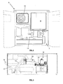
- the transportable bottling plant shown in figure 1 is integrated into a container 1, in particular a standard ISO 20 ft container.
- a container 1 in particular a standard ISO 20 ft container.
- the plant is adapted for being quickly transported to a place of need, which can for example be a place struck by a calamity, a remote place where military operations take place (e.g. desert), a stationary bottling plant which has insufficient capacity to meet the demand, or other.
- the container 1 has a front side 2 opposite a back side 3, which form the shorter sides of the container, and two opposite lateral sides 4 and 5, which form the longer sides of the container.
- the container 1 has a separation wall 6 which divides the interior of the container into a bottling room 7 and a technical room 8.
- the bottling room 7 contains all the electrically powered units for manufacturing closed and filled drinking water bottles starting from a supply of consumables, in particular plastic bottle preforms, bottle caps, bottle carrying handles and labels, and a supply of drinking water.
- the technical room 8, shown in figure 2 contains an air compressor 9 for supplying pressurised air, the condenser part 10 of an air conditioning system for conditioning/cooling the air in the bottling room and a fuel driven electric power generator 11 for generating the electric power for the units in the bottling room 7 and also the compressor and the air conditioning system.
- the compressor 9 is provided for supplying pressurised air of 15 bar, which implies that the plant can be used for making bottles of up to 5 I from suitable preforms. For larger bottles, a higher air pressure is needed.
- the bottling plant of figure 1 is shown making 5 I bottles but can with minor modifications also be used for making bottles of for example 1, 1.5, 2 l or any volume from 0,25 up to 5 l. In particular, for the smaller bottles a different mould is used and the handle applicator is usually not used.
- the air compressor 9 has to be able to sustain a reliable supply of pressurised air at 15 bar also in extreme conditions (e.g. 55°C and 85% humidity).
- the inventors preferred an air compressor of 18.5 kW power for the plant in the 20 ft container.
- the inventors preferred a power generator 11 having a power of 50 kVA (40 kW), driven by a 4 cylinder, 84 horsepower engine.
- the separation wall 6 provides both a thermal and an acoustic isolation between the bottling room 7 and the technical room 8.
- the wall preferably comprises a rockwool plate of 80 or 100 mm, such as for example the "Marine Slab 55" available from manufacturer Rockwool Technical Insulation NV.
- the air conditioning system shown in figure 2 is of the split type having a separate condenser unit 10 in the technical room and evaporator unit (not shown) inside the bottling room 7 against the separation wall 6.
- the air conditioning system could also be a unitary system, mounted in the same compartment of the technical room as the condenser unit 10 with then a grid towards the bottling room 7.
- the following units are provided in the bottling room 7: a preform feeder 12 for feeding and ordering the plastic bottle preforms, a first transferring device 13, a bottle blowing unit 14 for blowing plastic bottles from the preforms, a second transferring device 15 and a filling and closing unit 16.
- a preform feeder 12 for feeding and ordering the plastic bottle preforms
- a first transferring device 13 for transferring plastic bottles from the preforms
- a second transferring device 15 for blowing plastic bottles from the preforms
- a second transferring device 15 for blowing plastic bottles from the preforms
- a filling and closing unit 16 a filling and closing unit 16.
- these units provide a unit for every step in the bottling process, so that the bottling plant can run substantially without manual intervention. This also contributes to hygiene as no continuous presence of an operator in the bottling room is required.
- the units 12-16 will be described in more detail.
- the preform feeder 12 comprises a recipient 17 for receiving and buffering plastic bottle preforms.
- the recipient 17 is accessible via a first hatch 18 provided in the front wall 2 of the container.
- this first hatch 18 has a door which is tiltable around its bottom side up to a slanting position in which it forms a slide towards the recipient 17, so that an operator can easily throw in preforms from outside the bottling room 7 by emptying boxes of preforms onto the slide.
- the preforms present in the recipient 17 are picked up by a conveyor belt 19 and fed to an ordering unit 20.
- the ordering unit 20 arranges the preforms with their neck pointing upwards onto a slide/hopper 21, on which the preforms are transported towards the bottle blowing unit 14.
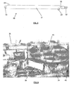
- the first transferring device 13 shown in detail in figure 4 , comprises a 180° rotatable arm with a gripping mechanism, by means of which the preforms are picked up one by one at their neck and placed upside down, i.e. with their neck pointing downwards onto preform/bottle holders 24 of the bottle blowing unit 14. Turning the preforms upside down at this stage has the advantage that any dirt present in the preforms can fall out.
- the bottle blowing unit 14, shown in detail in figure 4 comprises an array of preform/bottle holders 24 which are coupled in a semi-circular chain.
- the preforms are first moved into a heater 25 for heating up the preforms to the extent that the material of the bodies of the preforms becomes mouldable.
- This heater 25 is located at the straight part of the semi-circular chain.
- the chain of holders 24 is carried out in such a way that the distance between the holders 24 is minimal in the straight part of the chain, so that the preforms travel through the heater at a slow pace and remain a longer period of time in the heater 25. This has the advantage that the heating of the preforms to the desired level can be achieved with less power.
- a cooling system (not shown) is provided in the lower part of the heater for cooling the neck portions of the preforms in the heater.
- the fact that the preforms are held upside down while they are moved through the heater 25 has the advantage of avoiding that the necks of the preforms are heated up by the bodies (as hot air rises). This minimises the risk of deformation of the necks in subsequent stages of the bottling process.
- the distance between the holders 24 is increased, so that sufficient space is present between subsequent preforms for being able to blow the preforms to bottles.
- the mould 27 comprises two mould halves which are moved back and forth to open and close the mould.
- the mould 27 is cooled by means of a cooling circuit 28 which circulates a cooling liquid through the mould 27 and also the neck cooling system in the heater 25.
- the cooling circuit 28 is connected to a heat exchanger 29 which is in turn connected to supply ducts via which the drinking water is supplied to the filling and closing unit 16.
- This heat exchanger 29 comprises a double pipe with an inner pipe 30 conducting the drinking water and an outer pipe 31 conducting the cooling liquid. In this way, the double pipe is provided for transferring heat from the cooling liquid to the drinking water, before it enters the bottles.
- This cooling circuit 28 and heat exchanger 29 are schematically shown in figure 4 , the thinner lines indicating the flow of the cooling liquid and the thicker lines indicating the flow of the drinking water.
- the cooling liquid circulating in the cooling circuit 28 can be sufficiently cooled in this way. Tests have shown that the heat transfer in the heat exchanger 29 leads to a temperature increase in the drinking water of only 1 to 2 °C, which is negligible and does not affect the quality of the drinking water fed into the bottles.
- the heat exchanger 29 itself is shown in figure 5 . It comprises a double pipe with an inner pipe 30 with for conducting the drinking water and an outer pipe 31 conducting the cooling liquid.
- the inner pipe 30 comprises entrance and exit fittings 32, 33 for connecting drinking water conduits.
- the outer pipe 32 comprises entrance and exit fittings 22, 23 for connecting conduits of the cooling circuit 28.
- the second transferring device 15 shown in detail in figure 4 , comprises a 180° rotatable arm with a gripping mechanism, by means of which the bottles are picked up from the holders 24 one by one at their neck, turned over and placed upright, i.e. with their neck pointing upwards onto a conveyor belt 34 of the filling and closing unit 16.
- the filling and closing unit 16 shown in detail in figure 4 , comprises a glass housing 35 in which UV lamps (not shown) are provided for treatment of the drinking water, air, caps and bottles, and in which the filling operation takes place and the caps are screwed onto the bottles.
- UV treatment and the filling and closing operation are known from stationary bottling plants and therefore need no further description here.
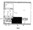
- the filling and closing unit 16 has a cap feeder 36 which feeds the caps from a cap recipient 45 (see figure 6 ) into the glass housing 35.
- the cap recipient 45 is a rotating table on which the caps can be placed via a second hatch 37 in the front side 2 of the container (see figure 7 ), so that no operator has to enter the bottling room in order to supply caps to the cap recipient 45.
- the filling and closing unit 16 further has a handle recipient for feeding bottle carrying handles to a handle applicator 38.
- This handle applicator 38 is shown in figure 1 to be next to the glass housing 35, but can also be integrated into the glass housing 35.
- the filled and closed bottles exiting the glass housing on the conveyor belt 34 then pass a labeller 39 (see figure 6 ) which applies a label to the bottle and prints a code identifying lot number and date onto the bottle.
- the finished bottles are transferred from the conveyor belt 34 inside the bottling room, passing a lock 40 in the front side of the container, towards an accumulation conveyor (not shown) outside the bottling container for further handling operations.
- This accumulation conveyor can be provided for being linked to the conveyor belt 34 and can for example be stored in the interior of the bottling room 7 during transportation or when not in use.
- the filling and closing unit 16 is provided with a water purification system (not shown), which is located in the space beneath the labeller 39.
- a tailor made 'Clean in Place' (CIP) system is provided in the filling and closing unit 16.
- the drinking water infeed connection 41 is used also as entrance for the cleaning product and is positioned in the outside wall of the container, see figure 9 .
- a separate outfeed connection 42 also positioned in the outside wall of the container, is used to evacuate the cleaning product.
- the infeed connection 43 for the water treatment chemicals for the water purification system is positioned in the outside wall 5 of the container, with a pump inside the container. This avoids water treatment chemicals to be brought inside the bottling room, which is advantageous for safety reasons, for easy operation and for eliminating possible chemical contamination inside the container.
- connection 44 shown in figure 9 is for a discharge of any overflow which may occur in the container during the operation.
- the front side 2 and back side 3 of the container are provided with conventional container doors by means of which the bottling room and the technical room can be closed off for the purposes of transportation.
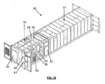
- Figure 10 shows an alternative embodiment of the transportable bottling plant of the invention.
- the container is a standard ISO 40 ft container.
- This plant is designed for making bottles of 10 I and uses pressurised air of 20-25 bar.
- space is not such a critical issue for this embodiment.
- the bottling room of this plant is similar to the one of the 20 ft embodiment described above and will hence not be further described here. In the following, the technical room of this plant will be briefly described.
- the technical room contains a power generator, an air compression system and air conditioning units.
- the air compression system is divided into two devices, namely a first compressor pressurising air up to 8 bar and a second compressor pressurising air from 8 bar up to 20-25 bar.
- Each compressor has its own air dryer.
- Two air conditioning systems are provided, one for the bottling room and another for the technical room. The latter is provided in view of the fact that the efficiency and reliability of air compressors decreases at high temperatures, so by also cooling the technical room in this case, reliability and efficiency of the plant can be enhanced.
Landscapes
- Filling Of Jars Or Cans And Processes For Cleaning And Sealing Jars (AREA)
- Basic Packing Technique (AREA)
Priority Applications (2)
| Application Number | Priority Date | Filing Date | Title |
|---|---|---|---|
| PL10732321T PL2580153T3 (pl) | 2010-06-14 | 2010-06-14 | Przewoźna instalacja butelkująca w kontenerze |
| RS20150153A RS53879B1 (sr) | 2010-06-14 | 2010-06-14 | Prenosivo postrojenje za punjenje boca u kontejneru |
Applications Claiming Priority (1)
| Application Number | Priority Date | Filing Date | Title |
|---|---|---|---|
| PCT/EP2010/058326 WO2011157287A1 (en) | 2010-06-14 | 2010-06-14 | Transportable bottling plant in a container |
Publications (2)
| Publication Number | Publication Date |
|---|---|
| EP2580153A1 EP2580153A1 (en) | 2013-04-17 |
| EP2580153B1 true EP2580153B1 (en) | 2015-02-11 |
Family
ID=43646903
Family Applications (1)
| Application Number | Title | Priority Date | Filing Date |
|---|---|---|---|
| EP10732321.4A Active EP2580153B1 (en) | 2010-06-14 | 2010-06-14 | Transportable bottling plant in a container |
Country Status (11)
| Country | Link |
|---|---|
| EP (1) | EP2580153B1 (sr) |
| CN (1) | CN103108827B (sr) |
| AU (1) | AU2010355562B2 (sr) |
| BE (1) | BE1018788A3 (sr) |
| CA (1) | CA2802568A1 (sr) |
| EA (1) | EA023655B1 (sr) |
| ES (1) | ES2532505T3 (sr) |
| PL (1) | PL2580153T3 (sr) |
| RS (1) | RS53879B1 (sr) |
| WO (1) | WO2011157287A1 (sr) |
| ZA (1) | ZA201209456B (sr) |
Cited By (1)
| Publication number | Priority date | Publication date | Assignee | Title |
|---|---|---|---|---|
| DE102022123063A1 (de) | 2022-09-09 | 2024-03-14 | Krones Aktiengesellschaft | Kühlung der Blasmaschine ohne externen Kühler |
Families Citing this family (7)
| Publication number | Priority date | Publication date | Assignee | Title |
|---|---|---|---|---|
| WO2013113382A1 (en) * | 2012-02-01 | 2013-08-08 | Conteno | Bottle forming unit and transportable bottling plant |
| DE102014100733A1 (de) * | 2014-01-23 | 2015-07-23 | Krones Ag | Kühlsystem für Behälterbehandlungsanlagen |
| ITVI20140031U1 (it) * | 2014-07-02 | 2016-01-02 | Ferasin Daniele | Centro mobile di imbottigliamento |
| DE102015208280A1 (de) * | 2015-05-05 | 2016-11-10 | Krones Ag | Etikettiermaschine zum Anbringen eines Henkels an einen PET-Behälter |
| CN108793033A (zh) * | 2018-07-16 | 2018-11-13 | 新乡市恒星科技有限责任公司 | 一种润滑脂生产用存储罐灌装设备 |
| IT201900006708A1 (it) * | 2019-05-10 | 2020-11-10 | Gruppo Bisaro Sifa Srl | Stazione di lavoro, impianto e procedimento per produrre e riempire fusti per bevande. |
| CN115092869B (zh) * | 2022-07-04 | 2024-05-28 | 广西百年沁泉水业有限公司 | 一种瓶装矿泉水灌装设备 |
Family Cites Families (3)
| Publication number | Priority date | Publication date | Assignee | Title |
|---|---|---|---|---|
| FR2268667A1 (en) * | 1974-04-26 | 1975-11-21 | Lonvaud Max | Mobile wine treating and bottling plant - has split level trailer housing conditioners and filters |
| NL8802060A (nl) * | 1988-08-19 | 1990-03-16 | Boerderijmelkveredeling P N B | Installatie voor de bereiding van yoghurt. |
| DE19615454A1 (de) * | 1996-04-19 | 1997-10-23 | Mayerhofer Lothar | Abfüllanlage für flüssige und pastöse Füllgüter in Behälter |
-
2010
- 2010-06-14 WO PCT/EP2010/058326 patent/WO2011157287A1/en not_active Ceased
- 2010-06-14 AU AU2010355562A patent/AU2010355562B2/en not_active Ceased
- 2010-06-14 ES ES10732321.4T patent/ES2532505T3/es active Active
- 2010-06-14 CA CA2802568A patent/CA2802568A1/en not_active Abandoned
- 2010-06-14 EP EP10732321.4A patent/EP2580153B1/en active Active
- 2010-06-14 PL PL10732321T patent/PL2580153T3/pl unknown
- 2010-06-14 EA EA201270804A patent/EA023655B1/ru not_active IP Right Cessation
- 2010-06-14 RS RS20150153A patent/RS53879B1/sr unknown
- 2010-06-14 CN CN201080068346.5A patent/CN103108827B/zh not_active Expired - Fee Related
- 2010-11-08 BE BE2010/0660A patent/BE1018788A3/nl not_active IP Right Cessation
-
2012
- 2012-12-13 ZA ZA2012/09456A patent/ZA201209456B/en unknown
Cited By (1)
| Publication number | Priority date | Publication date | Assignee | Title |
|---|---|---|---|---|
| DE102022123063A1 (de) | 2022-09-09 | 2024-03-14 | Krones Aktiengesellschaft | Kühlung der Blasmaschine ohne externen Kühler |
Also Published As
| Publication number | Publication date |
|---|---|
| CA2802568A1 (en) | 2011-12-22 |
| AU2010355562A1 (en) | 2013-01-17 |
| CN103108827A (zh) | 2013-05-15 |
| EA201270804A1 (ru) | 2013-09-30 |
| EA023655B1 (ru) | 2016-06-30 |
| BE1018788A3 (nl) | 2011-08-02 |
| WO2011157287A1 (en) | 2011-12-22 |
| CN103108827B (zh) | 2014-10-29 |
| EP2580153A1 (en) | 2013-04-17 |
| ZA201209456B (en) | 2013-08-28 |
| ES2532505T3 (es) | 2015-03-27 |
| RS53879B1 (sr) | 2015-08-31 |
| PL2580153T3 (pl) | 2015-05-29 |
| AU2010355562B2 (en) | 2015-01-22 |
Similar Documents
| Publication | Publication Date | Title |
|---|---|---|
| US8479475B2 (en) | Transportable bottling plant in a container | |
| AU2010355562B2 (en) | Transportable bottling plant in a container | |
| EP2809608B1 (en) | Transportable bottling plant fitted into freight container | |
| CN102950755B (zh) | 吹塑机、饮料灌装设备和/或饮料容器生产设备及调换吹塑台部件的方法 | |
| JP6560316B2 (ja) | ボトル詰めライン及び方法 | |
| JP6043845B2 (ja) | 殺菌容器をブロー成形するための方法および装置 | |
| JP5600297B2 (ja) | 液体または液圧ブロー成形 | |
| CN102372162B (zh) | 无菌装瓶仪 | |
| JPH1191879A (ja) | 飲料の高純度ビン詰め方法及び装置 | |
| EP3284578B1 (en) | Bottling line and method | |
| US20110219728A1 (en) | Device and method for producing plastic containers | |
| MX2011000714A (es) | Sistema, aparato y metodo para transportar una pluralidad de recipientes. | |
| US20150231290A1 (en) | Method and apparatus for the sterilization of plastics material pre-forms with tempered housing | |
| WO2013113382A1 (en) | Bottle forming unit and transportable bottling plant | |
| JP6240766B2 (ja) | 無菌容器を製造する装置および方法 | |
| CA2332916A1 (en) | Transport system for chilled products | |
| WO2013113383A1 (en) | Arrangement and method for removing residual product from product circuit of bottling plant | |
| WO2017162274A1 (en) | Integrated unit for forming, filling and closing containers | |
| WO2013113381A1 (en) | Furnace for bottle forming unit | |
| AU763152B2 (en) | Temperature controlled container | |
| JP5753940B2 (ja) | ブロー成形システム及びこれを含む製造ライン並びにこれらで使用されるプリフォームコンベア | |
| CN221114670U (zh) | 一种纸箱包装机 |
Legal Events
| Date | Code | Title | Description |
|---|---|---|---|
| PUAI | Public reference made under article 153(3) epc to a published international application that has entered the european phase |
Free format text: ORIGINAL CODE: 0009012 |
|
| 17P | Request for examination filed |
Effective date: 20130114 |
|
| AK | Designated contracting states |
Kind code of ref document: A1 Designated state(s): AL AT BE BG CH CY CZ DE DK EE ES FI FR GB GR HR HU IE IS IT LI LT LU LV MC MK MT NL NO PL PT RO SE SI SK SM TR |
|
| AX | Request for extension of the european patent |
Extension state: RS |
|
| RAX | Requested extension states of the european patent have changed |
Extension state: RS Payment date: 20130114 |
|
| GRAP | Despatch of communication of intention to grant a patent |
Free format text: ORIGINAL CODE: EPIDOSNIGR1 |
|
| INTG | Intention to grant announced |
Effective date: 20140825 |
|
| GRAS | Grant fee paid |
Free format text: ORIGINAL CODE: EPIDOSNIGR3 |
|
| GRAA | (expected) grant |
Free format text: ORIGINAL CODE: 0009210 |
|
| AK | Designated contracting states |
Kind code of ref document: B1 Designated state(s): AL AT BE BG CH CY CZ DE DK EE ES FI FR GB GR HR HU IE IS IT LI LT LU LV MC MK MT NL NO PL PT RO SE SI SK SM TR |
|
| AX | Request for extension of the european patent |
Extension state: RS |
|
| REG | Reference to a national code |
Ref country code: GB Ref legal event code: FG4D |
|
| REG | Reference to a national code |
Ref country code: CH Ref legal event code: EP |
|
| REG | Reference to a national code |
Ref country code: NL Ref legal event code: T3 |
|
| REG | Reference to a national code |
Ref country code: IE Ref legal event code: FG4D |
|
| REG | Reference to a national code |
Ref country code: AT Ref legal event code: REF Ref document number: 709852 Country of ref document: AT Kind code of ref document: T Effective date: 20150315 |
|
| REG | Reference to a national code |
Ref country code: DE Ref legal event code: R096 Ref document number: 602010022205 Country of ref document: DE Effective date: 20150319 |
|
| REG | Reference to a national code |
Ref country code: ES Ref legal event code: FG2A Ref document number: 2532505 Country of ref document: ES Kind code of ref document: T3 Effective date: 20150327 |
|
| REG | Reference to a national code |
Ref country code: PL Ref legal event code: T3 |
|
| REG | Reference to a national code |
Ref country code: AT Ref legal event code: MK05 Ref document number: 709852 Country of ref document: AT Kind code of ref document: T Effective date: 20150211 |
|
| REG | Reference to a national code |
Ref country code: LT Ref legal event code: MG4D |
|
| PG25 | Lapsed in a contracting state [announced via postgrant information from national office to epo] |
Ref country code: LT Free format text: LAPSE BECAUSE OF FAILURE TO SUBMIT A TRANSLATION OF THE DESCRIPTION OR TO PAY THE FEE WITHIN THE PRESCRIBED TIME-LIMIT Effective date: 20150211 Ref country code: HR Free format text: LAPSE BECAUSE OF FAILURE TO SUBMIT A TRANSLATION OF THE DESCRIPTION OR TO PAY THE FEE WITHIN THE PRESCRIBED TIME-LIMIT Effective date: 20150211 Ref country code: NO Free format text: LAPSE BECAUSE OF FAILURE TO SUBMIT A TRANSLATION OF THE DESCRIPTION OR TO PAY THE FEE WITHIN THE PRESCRIBED TIME-LIMIT Effective date: 20150511 Ref country code: SE Free format text: LAPSE BECAUSE OF FAILURE TO SUBMIT A TRANSLATION OF THE DESCRIPTION OR TO PAY THE FEE WITHIN THE PRESCRIBED TIME-LIMIT Effective date: 20150211 Ref country code: FI Free format text: LAPSE BECAUSE OF FAILURE TO SUBMIT A TRANSLATION OF THE DESCRIPTION OR TO PAY THE FEE WITHIN THE PRESCRIBED TIME-LIMIT Effective date: 20150211 |
|
| PG25 | Lapsed in a contracting state [announced via postgrant information from national office to epo] |
Ref country code: LV Free format text: LAPSE BECAUSE OF FAILURE TO SUBMIT A TRANSLATION OF THE DESCRIPTION OR TO PAY THE FEE WITHIN THE PRESCRIBED TIME-LIMIT Effective date: 20150211 Ref country code: IS Free format text: LAPSE BECAUSE OF FAILURE TO SUBMIT A TRANSLATION OF THE DESCRIPTION OR TO PAY THE FEE WITHIN THE PRESCRIBED TIME-LIMIT Effective date: 20150611 Ref country code: AT Free format text: LAPSE BECAUSE OF FAILURE TO SUBMIT A TRANSLATION OF THE DESCRIPTION OR TO PAY THE FEE WITHIN THE PRESCRIBED TIME-LIMIT Effective date: 20150211 Ref country code: GR Free format text: LAPSE BECAUSE OF FAILURE TO SUBMIT A TRANSLATION OF THE DESCRIPTION OR TO PAY THE FEE WITHIN THE PRESCRIBED TIME-LIMIT Effective date: 20150512 |
|
| PG25 | Lapsed in a contracting state [announced via postgrant information from national office to epo] |
Ref country code: RO Free format text: LAPSE BECAUSE OF FAILURE TO SUBMIT A TRANSLATION OF THE DESCRIPTION OR TO PAY THE FEE WITHIN THE PRESCRIBED TIME-LIMIT Effective date: 20150211 Ref country code: SK Free format text: LAPSE BECAUSE OF FAILURE TO SUBMIT A TRANSLATION OF THE DESCRIPTION OR TO PAY THE FEE WITHIN THE PRESCRIBED TIME-LIMIT Effective date: 20150211 Ref country code: EE Free format text: LAPSE BECAUSE OF FAILURE TO SUBMIT A TRANSLATION OF THE DESCRIPTION OR TO PAY THE FEE WITHIN THE PRESCRIBED TIME-LIMIT Effective date: 20150211 Ref country code: DK Free format text: LAPSE BECAUSE OF FAILURE TO SUBMIT A TRANSLATION OF THE DESCRIPTION OR TO PAY THE FEE WITHIN THE PRESCRIBED TIME-LIMIT Effective date: 20150211 Ref country code: CZ Free format text: LAPSE BECAUSE OF FAILURE TO SUBMIT A TRANSLATION OF THE DESCRIPTION OR TO PAY THE FEE WITHIN THE PRESCRIBED TIME-LIMIT Effective date: 20150211 |
|
| REG | Reference to a national code |
Ref country code: DE Ref legal event code: R097 Ref document number: 602010022205 Country of ref document: DE |
|
| PLBE | No opposition filed within time limit |
Free format text: ORIGINAL CODE: 0009261 |
|
| STAA | Information on the status of an ep patent application or granted ep patent |
Free format text: STATUS: NO OPPOSITION FILED WITHIN TIME LIMIT |
|
| 26N | No opposition filed |
Effective date: 20151112 |
|
| PG25 | Lapsed in a contracting state [announced via postgrant information from national office to epo] |
Ref country code: MC Free format text: LAPSE BECAUSE OF FAILURE TO SUBMIT A TRANSLATION OF THE DESCRIPTION OR TO PAY THE FEE WITHIN THE PRESCRIBED TIME-LIMIT Effective date: 20150211 |
|
| REG | Reference to a national code |
Ref country code: CH Ref legal event code: PL |
|
| PG25 | Lapsed in a contracting state [announced via postgrant information from national office to epo] |
Ref country code: SI Free format text: LAPSE BECAUSE OF FAILURE TO SUBMIT A TRANSLATION OF THE DESCRIPTION OR TO PAY THE FEE WITHIN THE PRESCRIBED TIME-LIMIT Effective date: 20150211 Ref country code: LU Free format text: LAPSE BECAUSE OF FAILURE TO SUBMIT A TRANSLATION OF THE DESCRIPTION OR TO PAY THE FEE WITHIN THE PRESCRIBED TIME-LIMIT Effective date: 20150614 |
|
| REG | Reference to a national code |
Ref country code: IE Ref legal event code: MM4A |
|
| PG25 | Lapsed in a contracting state [announced via postgrant information from national office to epo] |
Ref country code: IE Free format text: LAPSE BECAUSE OF NON-PAYMENT OF DUE FEES Effective date: 20150614 Ref country code: LI Free format text: LAPSE BECAUSE OF NON-PAYMENT OF DUE FEES Effective date: 20150630 Ref country code: CH Free format text: LAPSE BECAUSE OF NON-PAYMENT OF DUE FEES Effective date: 20150630 |
|
| PG25 | Lapsed in a contracting state [announced via postgrant information from national office to epo] |
Ref country code: BE Free format text: LAPSE BECAUSE OF FAILURE TO SUBMIT A TRANSLATION OF THE DESCRIPTION OR TO PAY THE FEE WITHIN THE PRESCRIBED TIME-LIMIT Effective date: 20150211 |
|
| REG | Reference to a national code |
Ref country code: FR Ref legal event code: PLFP Year of fee payment: 7 |
|
| PGFP | Annual fee paid to national office [announced via postgrant information from national office to epo] |
Ref country code: NL Payment date: 20160629 Year of fee payment: 7 Ref country code: FR Payment date: 20160629 Year of fee payment: 7 |
|
| REG | Reference to a national code |
Ref country code: FR Ref legal event code: CA Effective date: 20160817 |
|
| PGFP | Annual fee paid to national office [announced via postgrant information from national office to epo] |
Ref country code: DE Payment date: 20160712 Year of fee payment: 7 Ref country code: IT Payment date: 20160630 Year of fee payment: 7 Ref country code: GB Payment date: 20160721 Year of fee payment: 7 |
|
| PGFP | Annual fee paid to national office [announced via postgrant information from national office to epo] |
Ref country code: PL Payment date: 20160823 Year of fee payment: 7 |
|
| PG25 | Lapsed in a contracting state [announced via postgrant information from national office to epo] |
Ref country code: MT Free format text: LAPSE BECAUSE OF FAILURE TO SUBMIT A TRANSLATION OF THE DESCRIPTION OR TO PAY THE FEE WITHIN THE PRESCRIBED TIME-LIMIT Effective date: 20150211 |
|
| PGFP | Annual fee paid to national office [announced via postgrant information from national office to epo] |
Ref country code: TR Payment date: 20160822 Year of fee payment: 7 Ref country code: ES Payment date: 20160715 Year of fee payment: 7 |
|
| PG25 | Lapsed in a contracting state [announced via postgrant information from national office to epo] |
Ref country code: HU Free format text: LAPSE BECAUSE OF FAILURE TO SUBMIT A TRANSLATION OF THE DESCRIPTION OR TO PAY THE FEE WITHIN THE PRESCRIBED TIME-LIMIT; INVALID AB INITIO Effective date: 20100614 Ref country code: BG Free format text: LAPSE BECAUSE OF FAILURE TO SUBMIT A TRANSLATION OF THE DESCRIPTION OR TO PAY THE FEE WITHIN THE PRESCRIBED TIME-LIMIT Effective date: 20150211 Ref country code: SM Free format text: LAPSE BECAUSE OF FAILURE TO SUBMIT A TRANSLATION OF THE DESCRIPTION OR TO PAY THE FEE WITHIN THE PRESCRIBED TIME-LIMIT Effective date: 20150211 |
|
| PG25 | Lapsed in a contracting state [announced via postgrant information from national office to epo] |
Ref country code: CY Free format text: LAPSE BECAUSE OF FAILURE TO SUBMIT A TRANSLATION OF THE DESCRIPTION OR TO PAY THE FEE WITHIN THE PRESCRIBED TIME-LIMIT Effective date: 20150211 |
|
| REG | Reference to a national code |
Ref country code: DE Ref legal event code: R119 Ref document number: 602010022205 Country of ref document: DE |
|
| REG | Reference to a national code |
Ref country code: NL Ref legal event code: MM Effective date: 20170701 |
|
| GBPC | Gb: european patent ceased through non-payment of renewal fee |
Effective date: 20170614 |
|
| PG25 | Lapsed in a contracting state [announced via postgrant information from national office to epo] |
Ref country code: NL Free format text: LAPSE BECAUSE OF NON-PAYMENT OF DUE FEES Effective date: 20170701 |
|
| REG | Reference to a national code |
Ref country code: FR Ref legal event code: ST Effective date: 20180228 |
|
| PG25 | Lapsed in a contracting state [announced via postgrant information from national office to epo] |
Ref country code: DE Free format text: LAPSE BECAUSE OF NON-PAYMENT OF DUE FEES Effective date: 20180103 Ref country code: GB Free format text: LAPSE BECAUSE OF NON-PAYMENT OF DUE FEES Effective date: 20170614 |
|
| PG25 | Lapsed in a contracting state [announced via postgrant information from national office to epo] |
Ref country code: FR Free format text: LAPSE BECAUSE OF NON-PAYMENT OF DUE FEES Effective date: 20170630 Ref country code: IT Free format text: LAPSE BECAUSE OF NON-PAYMENT OF DUE FEES Effective date: 20170614 |
|
| PG25 | Lapsed in a contracting state [announced via postgrant information from national office to epo] |
Ref country code: PT Free format text: LAPSE BECAUSE OF FAILURE TO SUBMIT A TRANSLATION OF THE DESCRIPTION OR TO PAY THE FEE WITHIN THE PRESCRIBED TIME-LIMIT Effective date: 20150211 Ref country code: MK Free format text: LAPSE BECAUSE OF FAILURE TO SUBMIT A TRANSLATION OF THE DESCRIPTION OR TO PAY THE FEE WITHIN THE PRESCRIBED TIME-LIMIT Effective date: 20150211 |
|
| PG25 | Lapsed in a contracting state [announced via postgrant information from national office to epo] |
Ref country code: AL Free format text: LAPSE BECAUSE OF FAILURE TO SUBMIT A TRANSLATION OF THE DESCRIPTION OR TO PAY THE FEE WITHIN THE PRESCRIBED TIME-LIMIT Effective date: 20150211 |
|
| REG | Reference to a national code |
Ref country code: ES Ref legal event code: FD2A Effective date: 20181106 |
|
| PG25 | Lapsed in a contracting state [announced via postgrant information from national office to epo] |
Ref country code: PL Free format text: LAPSE BECAUSE OF NON-PAYMENT OF DUE FEES Effective date: 20170614 |
|
| PG25 | Lapsed in a contracting state [announced via postgrant information from national office to epo] |
Ref country code: ES Free format text: LAPSE BECAUSE OF NON-PAYMENT OF DUE FEES Effective date: 20170615 |
|
| PG25 | Lapsed in a contracting state [announced via postgrant information from national office to epo] |
Ref country code: TR Free format text: LAPSE BECAUSE OF NON-PAYMENT OF DUE FEES Effective date: 20170614 |