EP2580532B1 - Agencements de ventilation - Google Patents
Agencements de ventilation Download PDFInfo
- Publication number
- EP2580532B1 EP2580532B1 EP11738771.2A EP11738771A EP2580532B1 EP 2580532 B1 EP2580532 B1 EP 2580532B1 EP 11738771 A EP11738771 A EP 11738771A EP 2580532 B1 EP2580532 B1 EP 2580532B1
- Authority
- EP
- European Patent Office
- Prior art keywords
- components
- passage
- ventilation arrangement
- arrangement according
- ventilation
- Prior art date
- Legal status (The legal status is an assumption and is not a legal conclusion. Google has not performed a legal analysis and makes no representation as to the accuracy of the status listed.)
- Active
Links
Images


Classifications
-
- F—MECHANICAL ENGINEERING; LIGHTING; HEATING; WEAPONS; BLASTING
- F24—HEATING; RANGES; VENTILATING
- F24F—AIR-CONDITIONING; AIR-HUMIDIFICATION; VENTILATION; USE OF AIR CURRENTS FOR SCREENING
- F24F7/00—Ventilation
- F24F7/02—Roof ventilation
-
- F—MECHANICAL ENGINEERING; LIGHTING; HEATING; WEAPONS; BLASTING
- F24—HEATING; RANGES; VENTILATING
- F24F—AIR-CONDITIONING; AIR-HUMIDIFICATION; VENTILATION; USE OF AIR CURRENTS FOR SCREENING
- F24F13/00—Details common to, or for air-conditioning, air-humidification, ventilation or use of air currents for screening
- F24F13/08—Air-flow control members, e.g. louvres, grilles, flaps or guide plates
-
- F—MECHANICAL ENGINEERING; LIGHTING; HEATING; WEAPONS; BLASTING
- F24—HEATING; RANGES; VENTILATING
- F24F—AIR-CONDITIONING; AIR-HUMIDIFICATION; VENTILATION; USE OF AIR CURRENTS FOR SCREENING
- F24F13/00—Details common to, or for air-conditioning, air-humidification, ventilation or use of air currents for screening
- F24F13/08—Air-flow control members, e.g. louvres, grilles, flaps or guide plates
- F24F13/081—Air-flow control members, e.g. louvres, grilles, flaps or guide plates for guiding air around a curve
-
- F—MECHANICAL ENGINEERING; LIGHTING; HEATING; WEAPONS; BLASTING
- F24—HEATING; RANGES; VENTILATING
- F24F—AIR-CONDITIONING; AIR-HUMIDIFICATION; VENTILATION; USE OF AIR CURRENTS FOR SCREENING
- F24F13/00—Details common to, or for air-conditioning, air-humidification, ventilation or use of air currents for screening
- F24F13/08—Air-flow control members, e.g. louvres, grilles, flaps or guide plates
- F24F13/082—Grilles, registers or guards
-
- F—MECHANICAL ENGINEERING; LIGHTING; HEATING; WEAPONS; BLASTING
- F24—HEATING; RANGES; VENTILATING
- F24F—AIR-CONDITIONING; AIR-HUMIDIFICATION; VENTILATION; USE OF AIR CURRENTS FOR SCREENING
- F24F13/00—Details common to, or for air-conditioning, air-humidification, ventilation or use of air currents for screening
- F24F13/08—Air-flow control members, e.g. louvres, grilles, flaps or guide plates
- F24F13/10—Air-flow control members, e.g. louvres, grilles, flaps or guide plates movable, e.g. dampers
- F24F13/12—Air-flow control members, e.g. louvres, grilles, flaps or guide plates movable, e.g. dampers built up of sliding members
-
- F—MECHANICAL ENGINEERING; LIGHTING; HEATING; WEAPONS; BLASTING
- F24—HEATING; RANGES; VENTILATING
- F24F—AIR-CONDITIONING; AIR-HUMIDIFICATION; VENTILATION; USE OF AIR CURRENTS FOR SCREENING
- F24F13/00—Details common to, or for air-conditioning, air-humidification, ventilation or use of air currents for screening
- F24F13/08—Air-flow control members, e.g. louvres, grilles, flaps or guide plates
- F24F13/10—Air-flow control members, e.g. louvres, grilles, flaps or guide plates movable, e.g. dampers
- F24F13/14—Air-flow control members, e.g. louvres, grilles, flaps or guide plates movable, e.g. dampers built up of tilting members, e.g. louvre
-
- F—MECHANICAL ENGINEERING; LIGHTING; HEATING; WEAPONS; BLASTING
- F24—HEATING; RANGES; VENTILATING
- F24F—AIR-CONDITIONING; AIR-HUMIDIFICATION; VENTILATION; USE OF AIR CURRENTS FOR SCREENING
- F24F2221/00—Details or features not otherwise provided for
- F24F2221/52—Weather protecting means, e.g. against wind, rain or snow
Definitions
- the present invention relates to a ventilation arrangement for ventilating a building interior.
- Air conditioning or other mechanical ventilation systems can be used to provide ventilation to buildings to address these difficulties. However, such systems consume electricity and can, therefore, be relatively expensive to operate.
- One prior arrangement is to provide a duct extending from just above roof level into a building, with the upper end of the duct connecting to outwardly facing openings extending around the duct. During use air can enter the windward side of the duct through respective openings, with stale air exiting from the building through respective openings on the leeward side of the duct.
- the duct is divided by radial dividers, which could for instance divide the duct into four quadrants, with the quadrant nearest the windward side receiving the most air to ventilate the building, whilst the majority of air extracted from the building exits through the opposite quadrant on the leeward side of the arrangement.
- a ventilation arrangement for ventilating a building interior according to the preamble of claim 1 is known from document US 2 737 876 A . Such arrangements have operated successfully in providing ventilation with little or no power input. However, problems can be encountered in extreme weather with such arrangements, for example with very heavy rain and particularly snow, leading to ingress of precipitation into the apparatus.
- the passage may extend upwardly, and at an inclination of between 20 and 40°.
- the upper surface of an inner part of the passage may be concavely curved.
- the upper surface of the inner part of the passage may extend inwardly for a distance of between 35 and 60mm, and more particularly between 40 and 50mm.
- the curved upper surface of the inner part of the passage may have a radius of between 55 and 65mm.
- the upper surface of an outer part of the passage may be concavely curved.
- the upper surface of the outer part of the passage may extend inwardly for a distance of between 35 and 60mm, and more particularly between 40 and 50mm.
- the curved upper surface of the outer part of the passage may have a radius of between 30 and 50mm, and more particularly between 35 and 45mm.
- the outermost part of the upper surface of the outer part of the passage may extend substantially vertically.
- the lower surface of an inner part of the passage may be concavely curved to accelerate air entering through the passage.
- the lower surface of the inner part of the passage may have a radius of between 35 and 45m.
- the mouth of the ventilation opening may be between 30 and 70mm wide, and more particularly between 40 and 60mm wide, and especially between 45 and 55mm wide.
- the first components may be moveable over a distance of 40 and 70mm, and more particularly 50 and 60mm, between fully open and fully close positions.
- the first components may each extend vertically for between 40 and 70mm, and more particularly 50 and 60mm.
- the second components may define an outer part of the passage when open, with the first components defining an inner part of the passage.
- the first components may have concave upper and lower surfaces.
- the underside of the second components at least at an outer part thereof, may be concave.
- the degree of concavity of the second components may be greater than that of the first components.
- a substantially vertical downwardly facing slot may be provided in the first components towards the external side thereof, which slot is slidingly locatable over a formation on a respective second component, such that when the slot is fully located over the formation the passage is fully open, and as the first components are moved relative to the second components the slot is moved off the formation causing closing of the respective passage.
- the slots may each extend vertically for between 40 and 70mm, and more particularly 50 and 60mm.
- the formation on the second components may be in the form of an upwardly extending flange provided on the inner edge of the second component.
- the ventilation arrangement may be substantially polygonal in plan view, with first and second components for each side of the polygon.
- the ventilation arrangement may be substantially rectangular in plan view.
- the movable first components may be interconnected so as to be simultaneously movable, and link members may interconnect the first components.
- link members may interconnect the first components.
- a respective one of a plurality of link members may interconnect respective ends of the first components.
- the link members may be interconnected, and may all be connected to an actuator member.
- Fig. 1 shows the exterior of a housing 10 of a ventilation arrangement which housing 10 is mountable on the roof of a building. Within the housing 10 is a duct which extends downwardly to transport air to and from the interior of the building.
- the housing 10 is substantially square in plan view, with a louvre arrangement 12 on each side of the arrangement 10.
- the louvre arrangement 12 is intended to receive air on a windward side of the housing 10 to enter the duct 18, and to expel air received through the duct 18 on the opposite leeward side.
- This invention relates to the louvre arrangement 12 which will now be considered in more detail.
- the size of the arrangement 12 can be determined by a particular situation, but likely dimensional ranges are included below.
- Each louvre arrangement 12 defines a plurality of passages 14 on the respective side of the housing 10, which passages 14 are selectively partially or wholly closable.
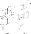
- Each louvre arrangement 12 comprises a plurality of spaced static second louvre components 16 on an external side of the louvre arrangement 12, and a plurality of spaced movable first louvre components 18 on an interior side thereof.
- the second louvre components have on an internal side an upstanding vertical flange 20 extending for between 40 and 70mm. Extending downwardly and outwardly for a horizontal distance of between 35 and 60mm from the flange 20 is a web 22, which interconnects to a further downwardly extending vertical flange 24, which flange 24 extends for between 25 and 50mm.
- the inner face of the flange 24 and an outer part of the web 22 is profiled to define a concave surface 26 with a radius of between 30 and 50mm, to urge air passing thereby to turn inwardly and downwardly.
- the first movable louvre components 18 are in the form of mouldings with concave upper and lower faces 28, 30, with a slightly greater degree of concavity on the upper faces 28, and respective radii in the ranges 35 to 45mm and 55 to 65mm.
- a downwardly facing slot 32 is provided adjacent the external edge of the first components 18, and is of a size to slidingly fit over the flange 20 of the second components.
- the first moveable components 18 have a height of between 40 and 70mm, and a depth of between 35 and 60mm.
- the first movable components 18 are interconnected by linkage bars 34 at their respective ends.
- Fig. 4 shows two such linkage bars 34 attached to the first components 18, though in Fig. 4 the first and second components 18, 16 have been shown diagrammatically and not with their full profile.
- the linkage bars 34 are all interconnected by cross bars 36 one of which is shown in Fig. 4 , and the cross bars 36 are attached to an actuator member (not shown) for actuation.
- the actuation may be provided manually, or by an electric motor or an actuator, and automatic operation thereof may be provided.
- the right hand most arrow 38 shows the air entering into the interior of the ventilation arrangement 10 substantially horizontally, as opposed to in the direction of the outer part of the passage defined by the web 22, which would generally be at an upwards inclination of between 20 and 40°.
- the first louvre components 18 can be moved upwardly such that the slot 32 moves off the vertical flange 20, and the components 18 can be moved to a fully closed position as shown in Fig. 3 .
Landscapes
- Engineering & Computer Science (AREA)
- Chemical & Material Sciences (AREA)
- Combustion & Propulsion (AREA)
- Mechanical Engineering (AREA)
- General Engineering & Computer Science (AREA)
- Air-Flow Control Members (AREA)
- Building Environments (AREA)
Claims (15)
- Dispositif de ventilation (10) pour ventiler l'intérieur d'un bâtiment, le dispositif de ventilation comprenant : un conduit d'air qui s'étend en utilisation depuis le niveau du toit jusqu'à un intérieur du bâtiment à ventiler pour transporter de l'air entre l'extérieur et l'intérieur du bâtiment ; des ouvertures de ventilation (12) qui s'étendent autour d'une partie supérieure du conduit d'air pour diriger l'air en mouvement provoqué par le mouvement du vent dans ou hors du conduit d'air ; les ouvertures de ventilation ayant une configuration de ventelle définissant une pluralité de passages discrets, l'un au-dessus de l'autre ; la configuration de ventelle étant configurée de sorte que chaque passage (14) s'étend depuis l'extérieur jusque dans le dispositif de ventilation ; le passage (14) s'étendant de manière générale vers le haut vers l'intérieur pour éviter l'entrée de liquides et d'autres précipitations ;
caractérisé par la configuration de ventelle comprenant une pluralité de premiers composants mobiles (18) et de seconds composants statiques, les premiers composants étant mobiles simultanément l'un avec l'autre, chaque passage étant défini entre une paire respective de premiers composants et une paire respective de seconds composants ; les seconds composants (16) définissant une partie extérieure du passage lorsqu'ils sont ouverts, les premiers composants définissant une partie intérieure du passage ; une surface supérieure (30) de la partie intérieure du passage (14) étant courbée de manière concave pour pousser vers le bas l'air entrant à travers le passage depuis l'extérieur, et une surface inférieure (28) de la partie intérieure du passage étant courbée de manière concave pour pousser vers le haut l'air entrant à travers le passage depuis l'extérieur pour accélérer l'air entrant à travers le passage. - Dispositif de ventilation selon la revendication 1, dans lequel le passage (14) s'étend vers le haut, et avec une inclinaison comprise entre 20 et 40 °.
- Dispositif de ventilation selon la revendication 1 ou 2, dans lequel la surface supérieure de la partie intérieure du passage (14) s'étend vers l'intérieur sur une distance comprise entre 35 et 60 mm et peut s'étendre vers l'intérieur sur une distance comprise entre 40 et 50 mm, et la surface supérieure incurvée de la partie interne du passage peut avoir un rayon compris entre 55 et 65 mm.
- Dispositif de ventilation selon l'une quelconque des revendications précédentes, dans lequel la surface supérieure (26) d'une partie extérieure du passage est courbée de manière concave, laquelle surface supérieure de la partie extérieure du passage peut s'étendre vers l'intérieur sur une distance comprise entre 35 et 60 mm, et peut s'étendre vers l'intérieur sur une distance comprise entre 40 et 50 mm.
- Dispositif de ventilation selon la revendication 4, dans lequel la surface supérieure incurvée (26) de la partie extérieure du passage a un rayon compris entre 30 et 50 mm et peut avoir un rayon compris entre 35 et 45 mm.
- Dispositif de ventilation selon la revendication 4 ou 5, dans lequel la partie la plus extérieure de la surface supérieure (26) de la partie extérieure du passage s'étend sensiblement verticalement.
- Dispositif de ventilation selon la revendication 6, dans lequel la surface inférieure (28) de la partie intérieure du passage a un rayon compris entre 35 et 45 mm.
- Dispositif de ventilation selon l'une quelconque des revendications précédentes, dans lequel l'embouchure de l'ouverture de ventilation (12) a une largeur comprise entre 30 et 70 mm et peut être comprise entre 40 et 60 mm de large, et peut être comprise entre 45 et 55 mm de large.
- Dispositif de ventilation selon l'une quelconque des revendications précédentes, dans lequel les premiers composants (18) sont mobiles sur une distance de 40 et 70 mm entre des positions complètement ouvertes et complètement fermées, et peuvent être mobiles sur une distance de 50 et 60 mm entre des positions complètement ouvertes et complètement fermées.
- Dispositif de ventilation selon l'une quelconque des revendications précédentes, dans lequel les premiers composants (18) s'étendent chacun verticalement sur une distance comprise entre 40 et 70 mm et peuvent s'étendre verticalement sur une distance comprise entre 50 et 60 mm.
- Dispositif de ventilation selon l'une quelconque des revendications précédentes, dans lequel la face inférieure des seconds composants (16), au moins au niveau d'une partie extérieure de celle-ci, est concave et le degré de concavité des seconds composants peut être supérieur à celui des premiers composants.
- Dispositif de ventilation selon l'une quelconque des revendications précédentes, dans lequel une fente (32) sensiblement verticale dirigée vers le bas est prévue dans les premiers composants vers le côté externe de ceux-ci, laquelle fente peut être positionnée de manière coulissante sur une formation sur un second composant respectif, de sorte que lorsque la fente est entièrement située au-dessus de la formation, le passage est complètement ouvert, et lorsque les premiers composants sont déplacés par rapport aux seconds composants, la fente est déplacée hors de la formation provoquant la fermeture du passage respectif, et les fentes peuvent chacune s'étendre verticalement sur une distance comprise entre 40 et 70 mm, et peuvent s'étendre verticalement sur une distance comprise entre 50 et 60 mm.
- Dispositif de ventilation selon la revendication 12, dans lequel la formation sur les seconds composants (16) se présente sous la forme d'une bride (20) s'étendant vers le haut, prévue sur le bord intérieur du second composant.
- Dispositif de ventilation selon l'une quelconque des revendications précédentes, dans lequel le dispositif de ventilation est sensiblement polygonal en vue de dessus, avec des premier et second composants (18, 16) pour chaque côté du polygone, et le dispositif de ventilation peut être sensiblement rectangulaire en vue de dessus.
- Dispositif de ventilation selon l'une quelconque des revendications précédentes, dans lequel les premiers composants mobiles sont interconnectés de manière à être mobiles simultanément, et des éléments de liaison (34) peuvent interconnecter les premiers composants, et un élément respectif parmi une pluralité d'éléments de liaison peut interconnecter les extrémités respectives des premiers composants, lesquels éléments de liaison peuvent être interconnectés, et les éléments de liaison peuvent tous être connectés à un élément d'actionnement.
Applications Claiming Priority (2)
| Application Number | Priority Date | Filing Date | Title |
|---|---|---|---|
| GB1012114.3A GB2482129B (en) | 2010-07-19 | 2010-07-19 | Ventilation arrangements |
| PCT/GB2011/001072 WO2012010825A1 (fr) | 2010-07-19 | 2011-07-18 | Agencements de ventilation |
Publications (2)
| Publication Number | Publication Date |
|---|---|
| EP2580532A1 EP2580532A1 (fr) | 2013-04-17 |
| EP2580532B1 true EP2580532B1 (fr) | 2017-06-21 |
Family
ID=42735161
Family Applications (1)
| Application Number | Title | Priority Date | Filing Date |
|---|---|---|---|
| EP11738771.2A Active EP2580532B1 (fr) | 2010-07-19 | 2011-07-18 | Agencements de ventilation |
Country Status (6)
| Country | Link |
|---|---|
| US (1) | US20130196587A1 (fr) |
| EP (1) | EP2580532B1 (fr) |
| CN (1) | CN103080661B (fr) |
| AU (1) | AU2011281363B2 (fr) |
| GB (1) | GB2482129B (fr) |
| WO (1) | WO2012010825A1 (fr) |
Families Citing this family (5)
| Publication number | Priority date | Publication date | Assignee | Title |
|---|---|---|---|---|
| GB201012115D0 (en) * | 2010-07-19 | 2010-09-01 | Monodraught Ltd | Ventillation arrangements |
| GB2510840A (en) * | 2013-02-14 | 2014-08-20 | Flakt Woods Ltd | A Ventilation Turret |
| FR3045138B1 (fr) * | 2015-12-15 | 2017-12-15 | Electricite De France | Grille de ventilation anti-intemperies |
| CN105903296B (zh) * | 2016-06-30 | 2019-01-04 | 李建农 | 空气清洗机 |
| CN112228967B (zh) * | 2020-10-14 | 2021-05-14 | 浙江都美电力科技有限公司 | 一体式环境调控装置和环境调控方法 |
Citations (2)
| Publication number | Priority date | Publication date | Assignee | Title |
|---|---|---|---|---|
| EP0222456A2 (fr) * | 1985-11-11 | 1987-05-20 | DEC Holding B.V. | Dispositif de ventilation constitué de parois à lamelles |
| GB2460095A (en) * | 2008-05-16 | 2009-11-18 | Univ Sheffield Hallam | Roof mounted building ventilator |
Family Cites Families (22)
| Publication number | Priority date | Publication date | Assignee | Title |
|---|---|---|---|---|
| US614368A (en) * | 1898-11-15 | Ventilator | ||
| US4255A (en) * | 1845-11-08 | Fracture apparatus | ||
| US1462343A (en) * | 1921-08-03 | 1923-07-17 | Thomas A Jenkins | Ventilator |
| US1672291A (en) * | 1926-05-04 | 1928-06-05 | Walter C Williams | Ventilator |
| US1996340A (en) * | 1934-06-18 | 1935-04-02 | John Spargo | Louver construction |
| US2594944A (en) * | 1948-12-15 | 1952-04-29 | Chelsea Products Inc | Automatic ventilating shutter |
| US2737876A (en) * | 1952-12-17 | 1956-03-13 | Lester L Smith | Ventilator structure |
| FR1104997A (fr) * | 1954-05-21 | 1955-11-25 | Tech Pour L Utilisation Des Al | Panneaux-persiennes métalliques pour climat tropical |
| US3426667A (en) * | 1967-03-17 | 1969-02-11 | American Warming Ventilation | Air intake apparatus |
| US3643584A (en) * | 1970-06-08 | 1972-02-22 | Exitaire Co The | Readily assembled ventilator housing |
| US3822637A (en) * | 1973-04-09 | 1974-07-09 | J Whitlock | Chimney draft control device |
| US4167898A (en) * | 1976-01-06 | 1979-09-18 | Barcant Kevin C | Illumination and ventilation system for buildings |
| US5048253A (en) * | 1991-01-02 | 1991-09-17 | Construction Specialties, Inc. | Louver with maximum free area |
| US5595068A (en) * | 1995-12-15 | 1997-01-21 | Carrier Corporation | Ceiling mounted indoor unit for an air conditioning system |
| JP3260328B2 (ja) * | 1998-10-06 | 2002-02-25 | 株式会社筑紫工業 | 開閉式ガラリ |
| US6814659B2 (en) * | 2002-10-31 | 2004-11-09 | Illinois Tool Works Inc. | Louver configuration for welding apparatus |
| US6769263B1 (en) * | 2003-05-30 | 2004-08-03 | Armour Magnetic Components, Inc. | Refrigerator air control baffle assembly with deicing mechanism |
| GB2411716B (en) * | 2004-03-05 | 2006-03-01 | Levolux At Ltd | An architectural weather louvre |
| AU2006350946B2 (en) * | 2006-11-17 | 2012-01-19 | Ramsay, Linda | Static roof ventilator |
| US20080127403A1 (en) * | 2006-11-30 | 2008-06-05 | Airex, Inc. | Ventilating fan with grill having high static pressure resistance |
| US20090130970A1 (en) * | 2007-11-21 | 2009-05-21 | Corey Scott Jacak | Exhaust fan and method of operating the same |
| GB0912280D0 (en) * | 2009-07-15 | 2009-08-26 | Monodraught Ltd | Ventilation arrangements |
-
2010
- 2010-07-19 GB GB1012114.3A patent/GB2482129B/en not_active Expired - Fee Related
-
2011
- 2011-07-18 AU AU2011281363A patent/AU2011281363B2/en not_active Ceased
- 2011-07-18 CN CN201180042895.XA patent/CN103080661B/zh active Active
- 2011-07-18 US US13/810,495 patent/US20130196587A1/en not_active Abandoned
- 2011-07-18 WO PCT/GB2011/001072 patent/WO2012010825A1/fr not_active Ceased
- 2011-07-18 EP EP11738771.2A patent/EP2580532B1/fr active Active
Patent Citations (2)
| Publication number | Priority date | Publication date | Assignee | Title |
|---|---|---|---|---|
| EP0222456A2 (fr) * | 1985-11-11 | 1987-05-20 | DEC Holding B.V. | Dispositif de ventilation constitué de parois à lamelles |
| GB2460095A (en) * | 2008-05-16 | 2009-11-18 | Univ Sheffield Hallam | Roof mounted building ventilator |
Also Published As
| Publication number | Publication date |
|---|---|
| CN103080661A (zh) | 2013-05-01 |
| US20130196587A1 (en) | 2013-08-01 |
| WO2012010825A1 (fr) | 2012-01-26 |
| AU2011281363A1 (en) | 2013-02-07 |
| GB2482129A (en) | 2012-01-25 |
| CN103080661B (zh) | 2016-05-25 |
| EP2580532A1 (fr) | 2013-04-17 |
| GB2482129B (en) | 2012-12-19 |
| AU2011281363B2 (en) | 2013-07-11 |
| GB201012114D0 (en) | 2010-09-01 |
Similar Documents
| Publication | Publication Date | Title |
|---|---|---|
| CN111819400B (zh) | 无动力换气件 | |
| CN108369017B (zh) | 无源屋顶排气系统及其方法 | |
| US7731477B2 (en) | Insulated housing apparatus for use with an attic fan | |
| US9557072B2 (en) | Vent cover | |
| AU2011281363B2 (en) | Ventilation arrangements | |
| US8303385B2 (en) | Stationary ventilating device | |
| EP1785675B1 (fr) | Dispositifs de ventilation | |
| US10619886B2 (en) | Airfoil damper | |
| EP2580530B1 (fr) | Agencements de ventilation | |
| US9163846B2 (en) | Ventilation apparatus arrangements | |
| CA2531538A1 (fr) | Systeme de ventilation | |
| EP2292985B1 (fr) | Agencements de ventilation | |
| KR20160038550A (ko) | 리노베이션 건물의 에너지절약 외피통풍구조 | |
| CN201447791U (zh) | 气楼 | |
| EP2580531B1 (fr) | Agencement de ventilation | |
| US8783245B2 (en) | Ventilation system for a range hood with exhaust and recirculation options | |
| EP2212485A1 (fr) | Système de paroi ou de plancher pour une maison ou un immeuble | |
| WO2002052112A1 (fr) | Systeme de ventilation pour serre ou element similaire | |
| KR101590723B1 (ko) | 수직통풍이 가능한 데크플레이트구조 | |
| JP4861685B2 (ja) | 換気構造及び換気方法 | |
| JP6842855B2 (ja) | 換気システム | |
| GB2510840A (en) | A Ventilation Turret | |
| AU2011200189A1 (en) | Ventilation arrangements | |
| TWM469460U (zh) | 導流排氣設備 | |
| AU2003268582A1 (en) | Vent |
Legal Events
| Date | Code | Title | Description |
|---|---|---|---|
| PUAI | Public reference made under article 153(3) epc to a published international application that has entered the european phase |
Free format text: ORIGINAL CODE: 0009012 |
|
| 17P | Request for examination filed |
Effective date: 20130114 |
|
| AK | Designated contracting states |
Kind code of ref document: A1 Designated state(s): AL AT BE BG CH CY CZ DE DK EE ES FI FR GB GR HR HU IE IS IT LI LT LU LV MC MK MT NL NO PL PT RO RS SE SI SK SM TR |
|
| DAX | Request for extension of the european patent (deleted) | ||
| 17Q | First examination report despatched |
Effective date: 20161019 |
|
| GRAP | Despatch of communication of intention to grant a patent |
Free format text: ORIGINAL CODE: EPIDOSNIGR1 |
|
| INTG | Intention to grant announced |
Effective date: 20170306 |
|
| GRAS | Grant fee paid |
Free format text: ORIGINAL CODE: EPIDOSNIGR3 |
|
| GRAA | (expected) grant |
Free format text: ORIGINAL CODE: 0009210 |
|
| AK | Designated contracting states |
Kind code of ref document: B1 Designated state(s): AL AT BE BG CH CY CZ DE DK EE ES FI FR GB GR HR HU IE IS IT LI LT LU LV MC MK MT NL NO PL PT RO RS SE SI SK SM TR |
|
| REG | Reference to a national code |
Ref country code: GB Ref legal event code: FG4D |
|
| REG | Reference to a national code |
Ref country code: CH Ref legal event code: EP |
|
| REG | Reference to a national code |
Ref country code: IE Ref legal event code: FG4D |
|
| REG | Reference to a national code |
Ref country code: AT Ref legal event code: REF Ref document number: 903318 Country of ref document: AT Kind code of ref document: T Effective date: 20170715 |
|
| REG | Reference to a national code |
Ref country code: DE Ref legal event code: R096 Ref document number: 602011038924 Country of ref document: DE |
|
| REG | Reference to a national code |
Ref country code: FR Ref legal event code: PLFP Year of fee payment: 7 |
|
| REG | Reference to a national code |
Ref country code: NL Ref legal event code: MP Effective date: 20170621 |
|
| PG25 | Lapsed in a contracting state [announced via postgrant information from national office to epo] |
Ref country code: GR Free format text: LAPSE BECAUSE OF FAILURE TO SUBMIT A TRANSLATION OF THE DESCRIPTION OR TO PAY THE FEE WITHIN THE PRESCRIBED TIME-LIMIT Effective date: 20170922 Ref country code: FI Free format text: LAPSE BECAUSE OF FAILURE TO SUBMIT A TRANSLATION OF THE DESCRIPTION OR TO PAY THE FEE WITHIN THE PRESCRIBED TIME-LIMIT Effective date: 20170621 Ref country code: LT Free format text: LAPSE BECAUSE OF FAILURE TO SUBMIT A TRANSLATION OF THE DESCRIPTION OR TO PAY THE FEE WITHIN THE PRESCRIBED TIME-LIMIT Effective date: 20170621 Ref country code: NO Free format text: LAPSE BECAUSE OF FAILURE TO SUBMIT A TRANSLATION OF THE DESCRIPTION OR TO PAY THE FEE WITHIN THE PRESCRIBED TIME-LIMIT Effective date: 20170921 Ref country code: HR Free format text: LAPSE BECAUSE OF FAILURE TO SUBMIT A TRANSLATION OF THE DESCRIPTION OR TO PAY THE FEE WITHIN THE PRESCRIBED TIME-LIMIT Effective date: 20170621 |
|
| REG | Reference to a national code |
Ref country code: LT Ref legal event code: MG4D |
|
| REG | Reference to a national code |
Ref country code: AT Ref legal event code: MK05 Ref document number: 903318 Country of ref document: AT Kind code of ref document: T Effective date: 20170621 |
|
| PG25 | Lapsed in a contracting state [announced via postgrant information from national office to epo] |
Ref country code: LV Free format text: LAPSE BECAUSE OF FAILURE TO SUBMIT A TRANSLATION OF THE DESCRIPTION OR TO PAY THE FEE WITHIN THE PRESCRIBED TIME-LIMIT Effective date: 20170621 Ref country code: RS Free format text: LAPSE BECAUSE OF FAILURE TO SUBMIT A TRANSLATION OF THE DESCRIPTION OR TO PAY THE FEE WITHIN THE PRESCRIBED TIME-LIMIT Effective date: 20170621 Ref country code: SE Free format text: LAPSE BECAUSE OF FAILURE TO SUBMIT A TRANSLATION OF THE DESCRIPTION OR TO PAY THE FEE WITHIN THE PRESCRIBED TIME-LIMIT Effective date: 20170621 Ref country code: BG Free format text: LAPSE BECAUSE OF FAILURE TO SUBMIT A TRANSLATION OF THE DESCRIPTION OR TO PAY THE FEE WITHIN THE PRESCRIBED TIME-LIMIT Effective date: 20170921 Ref country code: NL Free format text: LAPSE BECAUSE OF FAILURE TO SUBMIT A TRANSLATION OF THE DESCRIPTION OR TO PAY THE FEE WITHIN THE PRESCRIBED TIME-LIMIT Effective date: 20170621 |
|
| PG25 | Lapsed in a contracting state [announced via postgrant information from national office to epo] |
Ref country code: RO Free format text: LAPSE BECAUSE OF FAILURE TO SUBMIT A TRANSLATION OF THE DESCRIPTION OR TO PAY THE FEE WITHIN THE PRESCRIBED TIME-LIMIT Effective date: 20170621 Ref country code: AT Free format text: LAPSE BECAUSE OF FAILURE TO SUBMIT A TRANSLATION OF THE DESCRIPTION OR TO PAY THE FEE WITHIN THE PRESCRIBED TIME-LIMIT Effective date: 20170621 Ref country code: SK Free format text: LAPSE BECAUSE OF FAILURE TO SUBMIT A TRANSLATION OF THE DESCRIPTION OR TO PAY THE FEE WITHIN THE PRESCRIBED TIME-LIMIT Effective date: 20170621 Ref country code: CZ Free format text: LAPSE BECAUSE OF FAILURE TO SUBMIT A TRANSLATION OF THE DESCRIPTION OR TO PAY THE FEE WITHIN THE PRESCRIBED TIME-LIMIT Effective date: 20170621 Ref country code: EE Free format text: LAPSE BECAUSE OF FAILURE TO SUBMIT A TRANSLATION OF THE DESCRIPTION OR TO PAY THE FEE WITHIN THE PRESCRIBED TIME-LIMIT Effective date: 20170621 |
|
| PG25 | Lapsed in a contracting state [announced via postgrant information from national office to epo] |
Ref country code: IT Free format text: LAPSE BECAUSE OF FAILURE TO SUBMIT A TRANSLATION OF THE DESCRIPTION OR TO PAY THE FEE WITHIN THE PRESCRIBED TIME-LIMIT Effective date: 20170621 Ref country code: IS Free format text: LAPSE BECAUSE OF FAILURE TO SUBMIT A TRANSLATION OF THE DESCRIPTION OR TO PAY THE FEE WITHIN THE PRESCRIBED TIME-LIMIT Effective date: 20171021 Ref country code: SM Free format text: LAPSE BECAUSE OF FAILURE TO SUBMIT A TRANSLATION OF THE DESCRIPTION OR TO PAY THE FEE WITHIN THE PRESCRIBED TIME-LIMIT Effective date: 20170621 Ref country code: ES Free format text: LAPSE BECAUSE OF FAILURE TO SUBMIT A TRANSLATION OF THE DESCRIPTION OR TO PAY THE FEE WITHIN THE PRESCRIBED TIME-LIMIT Effective date: 20170621 Ref country code: PL Free format text: LAPSE BECAUSE OF FAILURE TO SUBMIT A TRANSLATION OF THE DESCRIPTION OR TO PAY THE FEE WITHIN THE PRESCRIBED TIME-LIMIT Effective date: 20170621 |
|
| REG | Reference to a national code |
Ref country code: CH Ref legal event code: PL |
|
| REG | Reference to a national code |
Ref country code: GB Ref legal event code: 732E Free format text: REGISTERED BETWEEN 20180208 AND 20180214 |
|
| REG | Reference to a national code |
Ref country code: DE Ref legal event code: R097 Ref document number: 602011038924 Country of ref document: DE |
|
| PG25 | Lapsed in a contracting state [announced via postgrant information from national office to epo] |
Ref country code: MC Free format text: LAPSE BECAUSE OF FAILURE TO SUBMIT A TRANSLATION OF THE DESCRIPTION OR TO PAY THE FEE WITHIN THE PRESCRIBED TIME-LIMIT Effective date: 20170621 |
|
| REG | Reference to a national code |
Ref country code: IE Ref legal event code: MM4A |
|
| PLBE | No opposition filed within time limit |
Free format text: ORIGINAL CODE: 0009261 |
|
| STAA | Information on the status of an ep patent application or granted ep patent |
Free format text: STATUS: NO OPPOSITION FILED WITHIN TIME LIMIT |
|
| PG25 | Lapsed in a contracting state [announced via postgrant information from national office to epo] |
Ref country code: CH Free format text: LAPSE BECAUSE OF NON-PAYMENT OF DUE FEES Effective date: 20170731 Ref country code: IE Free format text: LAPSE BECAUSE OF NON-PAYMENT OF DUE FEES Effective date: 20170718 Ref country code: DK Free format text: LAPSE BECAUSE OF FAILURE TO SUBMIT A TRANSLATION OF THE DESCRIPTION OR TO PAY THE FEE WITHIN THE PRESCRIBED TIME-LIMIT Effective date: 20170621 Ref country code: LI Free format text: LAPSE BECAUSE OF NON-PAYMENT OF DUE FEES Effective date: 20170731 |
|
| 26N | No opposition filed |
Effective date: 20180322 |
|
| REG | Reference to a national code |
Ref country code: BE Ref legal event code: MM Effective date: 20170731 |
|
| PG25 | Lapsed in a contracting state [announced via postgrant information from national office to epo] |
Ref country code: LU Free format text: LAPSE BECAUSE OF NON-PAYMENT OF DUE FEES Effective date: 20170718 |
|
| REG | Reference to a national code |
Ref country code: FR Ref legal event code: PLFP Year of fee payment: 8 |
|
| REG | Reference to a national code |
Ref country code: DE Ref legal event code: R082 Ref document number: 602011038924 Country of ref document: DE Representative=s name: PATENTANWAELTE MAGENBAUER & KOLLEGEN PARTNERSC, DE Ref country code: DE Ref legal event code: R081 Ref document number: 602011038924 Country of ref document: DE Owner name: MONODRAUGHT LTD., HIGH WYCOMBE, GB Free format text: FORMER OWNER: VKR HOLDING A/S, HOERSHOLM, DK |
|
| PG25 | Lapsed in a contracting state [announced via postgrant information from national office to epo] |
Ref country code: SI Free format text: LAPSE BECAUSE OF FAILURE TO SUBMIT A TRANSLATION OF THE DESCRIPTION OR TO PAY THE FEE WITHIN THE PRESCRIBED TIME-LIMIT Effective date: 20170621 Ref country code: BE Free format text: LAPSE BECAUSE OF NON-PAYMENT OF DUE FEES Effective date: 20170731 |
|
| PG25 | Lapsed in a contracting state [announced via postgrant information from national office to epo] |
Ref country code: MT Free format text: LAPSE BECAUSE OF NON-PAYMENT OF DUE FEES Effective date: 20170718 |
|
| PG25 | Lapsed in a contracting state [announced via postgrant information from national office to epo] |
Ref country code: HU Free format text: LAPSE BECAUSE OF FAILURE TO SUBMIT A TRANSLATION OF THE DESCRIPTION OR TO PAY THE FEE WITHIN THE PRESCRIBED TIME-LIMIT; INVALID AB INITIO Effective date: 20110718 |
|
| PG25 | Lapsed in a contracting state [announced via postgrant information from national office to epo] |
Ref country code: CY Free format text: LAPSE BECAUSE OF NON-PAYMENT OF DUE FEES Effective date: 20170621 |
|
| PG25 | Lapsed in a contracting state [announced via postgrant information from national office to epo] |
Ref country code: MK Free format text: LAPSE BECAUSE OF FAILURE TO SUBMIT A TRANSLATION OF THE DESCRIPTION OR TO PAY THE FEE WITHIN THE PRESCRIBED TIME-LIMIT Effective date: 20170621 |
|
| PG25 | Lapsed in a contracting state [announced via postgrant information from national office to epo] |
Ref country code: TR Free format text: LAPSE BECAUSE OF FAILURE TO SUBMIT A TRANSLATION OF THE DESCRIPTION OR TO PAY THE FEE WITHIN THE PRESCRIBED TIME-LIMIT Effective date: 20170621 |
|
| PG25 | Lapsed in a contracting state [announced via postgrant information from national office to epo] |
Ref country code: PT Free format text: LAPSE BECAUSE OF FAILURE TO SUBMIT A TRANSLATION OF THE DESCRIPTION OR TO PAY THE FEE WITHIN THE PRESCRIBED TIME-LIMIT Effective date: 20170621 |
|
| PG25 | Lapsed in a contracting state [announced via postgrant information from national office to epo] |
Ref country code: AL Free format text: LAPSE BECAUSE OF FAILURE TO SUBMIT A TRANSLATION OF THE DESCRIPTION OR TO PAY THE FEE WITHIN THE PRESCRIBED TIME-LIMIT Effective date: 20170621 |
|
| PGFP | Annual fee paid to national office [announced via postgrant information from national office to epo] |
Ref country code: GB Payment date: 20250616 Year of fee payment: 15 |
|
| PGFP | Annual fee paid to national office [announced via postgrant information from national office to epo] |
Ref country code: FR Payment date: 20250626 Year of fee payment: 15 |
|
| PGFP | Annual fee paid to national office [announced via postgrant information from national office to epo] |
Ref country code: DE Payment date: 20250630 Year of fee payment: 15 |