EP2581130A1 - Modular plant fo removal of pollutants from flue gases produced by industrial processes - Google Patents
Modular plant fo removal of pollutants from flue gases produced by industrial processes Download PDFInfo
- Publication number
- EP2581130A1 EP2581130A1 EP12199610.2A EP12199610A EP2581130A1 EP 2581130 A1 EP2581130 A1 EP 2581130A1 EP 12199610 A EP12199610 A EP 12199610A EP 2581130 A1 EP2581130 A1 EP 2581130A1
- Authority
- EP
- European Patent Office
- Prior art keywords
- section
- plant
- flue gas
- reaction
- gas
- Prior art date
- Legal status (The legal status is an assumption and is not a legal conclusion. Google has not performed a legal analysis and makes no representation as to the accuracy of the status listed.)
- Withdrawn
Links
Images








Classifications
-
- E—FIXED CONSTRUCTIONS
- E04—BUILDING
- E04H—BUILDINGS OR LIKE STRUCTURES FOR PARTICULAR PURPOSES; SWIMMING OR SPLASH BATHS OR POOLS; MASTS; FENCING; TENTS OR CANOPIES, IN GENERAL
- E04H5/00—Buildings or groups of buildings for industrial or agricultural purposes
- E04H5/02—Buildings or groups of buildings for industrial purposes, e.g. for power-plants or factories
-
- B—PERFORMING OPERATIONS; TRANSPORTING
- B01—PHYSICAL OR CHEMICAL PROCESSES OR APPARATUS IN GENERAL
- B01D—SEPARATION
- B01D53/00—Separation of gases or vapours; Recovering vapours of volatile solvents from gases; Chemical or biological purification of waste gases, e.g. engine exhaust gases, smoke, fumes, flue gases, aerosols
- B01D53/14—Separation of gases or vapours; Recovering vapours of volatile solvents from gases; Chemical or biological purification of waste gases, e.g. engine exhaust gases, smoke, fumes, flue gases, aerosols by absorption
- B01D53/18—Absorbing units; Liquid distributors therefor
-
- B—PERFORMING OPERATIONS; TRANSPORTING
- B01—PHYSICAL OR CHEMICAL PROCESSES OR APPARATUS IN GENERAL
- B01D—SEPARATION
- B01D53/00—Separation of gases or vapours; Recovering vapours of volatile solvents from gases; Chemical or biological purification of waste gases, e.g. engine exhaust gases, smoke, fumes, flue gases, aerosols
- B01D53/22—Separation of gases or vapours; Recovering vapours of volatile solvents from gases; Chemical or biological purification of waste gases, e.g. engine exhaust gases, smoke, fumes, flue gases, aerosols by diffusion
- B01D53/229—Integrated processes (Diffusion and at least one other process, e.g. adsorption, absorption)
-
- B—PERFORMING OPERATIONS; TRANSPORTING
- B01—PHYSICAL OR CHEMICAL PROCESSES OR APPARATUS IN GENERAL
- B01D—SEPARATION
- B01D53/00—Separation of gases or vapours; Recovering vapours of volatile solvents from gases; Chemical or biological purification of waste gases, e.g. engine exhaust gases, smoke, fumes, flue gases, aerosols
- B01D53/34—Chemical or biological purification of waste gases
- B01D53/74—General processes for purification of waste gases; Apparatus or devices specially adapted therefor
- B01D53/75—Multi-step processes
-
- B—PERFORMING OPERATIONS; TRANSPORTING
- B03—SEPARATION OF SOLID MATERIALS USING LIQUIDS OR USING PNEUMATIC TABLES OR JIGS; MAGNETIC OR ELECTROSTATIC SEPARATION OF SOLID MATERIALS FROM SOLID MATERIALS OR FLUIDS; SEPARATION BY HIGH-VOLTAGE ELECTRIC FIELDS
- B03C—MAGNETIC OR ELECTROSTATIC SEPARATION OF SOLID MATERIALS FROM SOLID MATERIALS OR FLUIDS; SEPARATION BY HIGH-VOLTAGE ELECTRIC FIELDS
- B03C3/00—Separating dispersed particles from gases or vapour, e.g. air, by electrostatic effect
- B03C3/017—Combinations of electrostatic separation with other processes, not otherwise provided for
-
- C—CHEMISTRY; METALLURGY
- C01—INORGANIC CHEMISTRY
- C01B—NON-METALLIC ELEMENTS; COMPOUNDS THEREOF; METALLOIDS OR COMPOUNDS THEREOF NOT COVERED BY SUBCLASS C01C
- C01B3/00—Hydrogen; Gaseous mixtures containing hydrogen; Separation of hydrogen from mixtures containing it; Purification of hydrogen; Reversible storage of hydrogen
- C01B3/02—Production of hydrogen; Production of gaseous mixtures containing hydrogen
- C01B3/06—Production of hydrogen; Production of gaseous mixtures containing hydrogen by reaction of inorganic compounds containing electro-positively bound hydrogen with inorganic reducing agents
- C01B3/103—Production of hydrogen; Production of gaseous mixtures containing hydrogen by reaction of inorganic compounds containing electro-positively bound hydrogen with inorganic reducing agents the hydrogen being generated from the water as a result of cycles of reactions, e.g. sulfur-iodine cycle
-
- C—CHEMISTRY; METALLURGY
- C07—ORGANIC CHEMISTRY
- C07C—ACYCLIC OR CARBOCYCLIC COMPOUNDS
- C07C29/00—Preparation of compounds having hydroxy or O-metal groups bound to a carbon atom not belonging to a six-membered aromatic ring
- C07C29/15—Preparation of compounds having hydroxy or O-metal groups bound to a carbon atom not belonging to a six-membered aromatic ring by reduction of oxides of carbon exclusively
- C07C29/151—Preparation of compounds having hydroxy or O-metal groups bound to a carbon atom not belonging to a six-membered aromatic ring by reduction of oxides of carbon exclusively with hydrogen or hydrogen-containing gases
- C07C29/152—Preparation of compounds having hydroxy or O-metal groups bound to a carbon atom not belonging to a six-membered aromatic ring by reduction of oxides of carbon exclusively with hydrogen or hydrogen-containing gases characterised by the reactor used
-
- B—PERFORMING OPERATIONS; TRANSPORTING
- B01—PHYSICAL OR CHEMICAL PROCESSES OR APPARATUS IN GENERAL
- B01D—SEPARATION
- B01D2251/00—Reactants
- B01D2251/40—Alkaline earth metal or magnesium compounds
- B01D2251/404—Alkaline earth metal or magnesium compounds of calcium
-
- B—PERFORMING OPERATIONS; TRANSPORTING
- B01—PHYSICAL OR CHEMICAL PROCESSES OR APPARATUS IN GENERAL
- B01D—SEPARATION
- B01D2256/00—Main component in the product gas stream after treatment
- B01D2256/16—Hydrogen
-
- B—PERFORMING OPERATIONS; TRANSPORTING
- B01—PHYSICAL OR CHEMICAL PROCESSES OR APPARATUS IN GENERAL
- B01D—SEPARATION
- B01D2257/00—Components to be removed
- B01D2257/20—Halogens or halogen compounds
- B01D2257/204—Inorganic halogen compounds
- B01D2257/2045—Hydrochloric acid
-
- B—PERFORMING OPERATIONS; TRANSPORTING
- B01—PHYSICAL OR CHEMICAL PROCESSES OR APPARATUS IN GENERAL
- B01D—SEPARATION
- B01D2257/00—Components to be removed
- B01D2257/20—Halogens or halogen compounds
- B01D2257/204—Inorganic halogen compounds
- B01D2257/2047—Hydrofluoric acid
-
- B—PERFORMING OPERATIONS; TRANSPORTING
- B01—PHYSICAL OR CHEMICAL PROCESSES OR APPARATUS IN GENERAL
- B01D—SEPARATION
- B01D2257/00—Components to be removed
- B01D2257/30—Sulfur compounds
- B01D2257/302—Sulfur oxides
-
- B—PERFORMING OPERATIONS; TRANSPORTING
- B01—PHYSICAL OR CHEMICAL PROCESSES OR APPARATUS IN GENERAL
- B01D—SEPARATION
- B01D2257/00—Components to be removed
- B01D2257/40—Nitrogen compounds
- B01D2257/404—Nitrogen oxides other than dinitrogen oxide
-
- B—PERFORMING OPERATIONS; TRANSPORTING
- B01—PHYSICAL OR CHEMICAL PROCESSES OR APPARATUS IN GENERAL
- B01D—SEPARATION
- B01D2257/00—Components to be removed
- B01D2257/50—Carbon oxides
- B01D2257/504—Carbon dioxide
-
- B—PERFORMING OPERATIONS; TRANSPORTING
- B01—PHYSICAL OR CHEMICAL PROCESSES OR APPARATUS IN GENERAL
- B01D—SEPARATION
- B01D2257/00—Components to be removed
- B01D2257/60—Heavy metals or heavy metal compounds
- B01D2257/602—Mercury or mercury compounds
-
- B—PERFORMING OPERATIONS; TRANSPORTING
- B01—PHYSICAL OR CHEMICAL PROCESSES OR APPARATUS IN GENERAL
- B01D—SEPARATION
- B01D2257/00—Components to be removed
- B01D2257/70—Organic compounds not provided for in groups B01D2257/00 - B01D2257/602
- B01D2257/702—Hydrocarbons
- B01D2257/7027—Aromatic hydrocarbons
-
- B—PERFORMING OPERATIONS; TRANSPORTING
- B01—PHYSICAL OR CHEMICAL PROCESSES OR APPARATUS IN GENERAL
- B01D—SEPARATION
- B01D53/00—Separation of gases or vapours; Recovering vapours of volatile solvents from gases; Chemical or biological purification of waste gases, e.g. engine exhaust gases, smoke, fumes, flue gases, aerosols
- B01D53/34—Chemical or biological purification of waste gases
- B01D53/74—General processes for purification of waste gases; Apparatus or devices specially adapted therefor
- B01D53/77—Liquid phase processes
-
- B—PERFORMING OPERATIONS; TRANSPORTING
- B01—PHYSICAL OR CHEMICAL PROCESSES OR APPARATUS IN GENERAL
- B01D—SEPARATION
- B01D53/00—Separation of gases or vapours; Recovering vapours of volatile solvents from gases; Chemical or biological purification of waste gases, e.g. engine exhaust gases, smoke, fumes, flue gases, aerosols
- B01D53/34—Chemical or biological purification of waste gases
- B01D53/74—General processes for purification of waste gases; Apparatus or devices specially adapted therefor
- B01D53/86—Catalytic processes
-
- B—PERFORMING OPERATIONS; TRANSPORTING
- B01—PHYSICAL OR CHEMICAL PROCESSES OR APPARATUS IN GENERAL
- B01J—CHEMICAL OR PHYSICAL PROCESSES, e.g. CATALYSIS OR COLLOID CHEMISTRY; THEIR RELEVANT APPARATUS
- B01J2219/00—Chemical, physical or physico-chemical processes in general; Their relevant apparatus
- B01J2219/00002—Chemical plants
- B01J2219/00018—Construction aspects
- B01J2219/0002—Plants assembled from modules joined together
-
- C—CHEMISTRY; METALLURGY
- C01—INORGANIC CHEMISTRY
- C01B—NON-METALLIC ELEMENTS; COMPOUNDS THEREOF; METALLOIDS OR COMPOUNDS THEREOF NOT COVERED BY SUBCLASS C01C
- C01B2203/00—Integrated processes for the production of hydrogen or synthesis gas
- C01B2203/04—Integrated processes for the production of hydrogen or synthesis gas containing a purification step for the hydrogen or the synthesis gas
- C01B2203/0465—Composition of the impurity
- C01B2203/0485—Composition of the impurity the impurity being a sulfur compound
-
- Y—GENERAL TAGGING OF NEW TECHNOLOGICAL DEVELOPMENTS; GENERAL TAGGING OF CROSS-SECTIONAL TECHNOLOGIES SPANNING OVER SEVERAL SECTIONS OF THE IPC; TECHNICAL SUBJECTS COVERED BY FORMER USPC CROSS-REFERENCE ART COLLECTIONS [XRACs] AND DIGESTS
- Y02—TECHNOLOGIES OR APPLICATIONS FOR MITIGATION OR ADAPTATION AGAINST CLIMATE CHANGE
- Y02C—CAPTURE, STORAGE, SEQUESTRATION OR DISPOSAL OF GREENHOUSE GASES [GHG]
- Y02C20/00—Capture or disposal of greenhouse gases
- Y02C20/40—Capture or disposal of greenhouse gases of CO2
-
- Y—GENERAL TAGGING OF NEW TECHNOLOGICAL DEVELOPMENTS; GENERAL TAGGING OF CROSS-SECTIONAL TECHNOLOGIES SPANNING OVER SEVERAL SECTIONS OF THE IPC; TECHNICAL SUBJECTS COVERED BY FORMER USPC CROSS-REFERENCE ART COLLECTIONS [XRACs] AND DIGESTS
- Y02—TECHNOLOGIES OR APPLICATIONS FOR MITIGATION OR ADAPTATION AGAINST CLIMATE CHANGE
- Y02E—REDUCTION OF GREENHOUSE GAS [GHG] EMISSIONS, RELATED TO ENERGY GENERATION, TRANSMISSION OR DISTRIBUTION
- Y02E60/00—Enabling technologies; Technologies with a potential or indirect contribution to GHG emissions mitigation
- Y02E60/30—Hydrogen technology
- Y02E60/36—Hydrogen production from non-carbon containing sources, e.g. by water electrolysis
-
- Y—GENERAL TAGGING OF NEW TECHNOLOGICAL DEVELOPMENTS; GENERAL TAGGING OF CROSS-SECTIONAL TECHNOLOGIES SPANNING OVER SEVERAL SECTIONS OF THE IPC; TECHNICAL SUBJECTS COVERED BY FORMER USPC CROSS-REFERENCE ART COLLECTIONS [XRACs] AND DIGESTS
- Y02—TECHNOLOGIES OR APPLICATIONS FOR MITIGATION OR ADAPTATION AGAINST CLIMATE CHANGE
- Y02P—CLIMATE CHANGE MITIGATION TECHNOLOGIES IN THE PRODUCTION OR PROCESSING OF GOODS
- Y02P20/00—Technologies relating to chemical industry
- Y02P20/151—Reduction of greenhouse gas [GHG] emissions, e.g. CO2
-
- Y—GENERAL TAGGING OF NEW TECHNOLOGICAL DEVELOPMENTS; GENERAL TAGGING OF CROSS-SECTIONAL TECHNOLOGIES SPANNING OVER SEVERAL SECTIONS OF THE IPC; TECHNICAL SUBJECTS COVERED BY FORMER USPC CROSS-REFERENCE ART COLLECTIONS [XRACs] AND DIGESTS
- Y02—TECHNOLOGIES OR APPLICATIONS FOR MITIGATION OR ADAPTATION AGAINST CLIMATE CHANGE
- Y02P—CLIMATE CHANGE MITIGATION TECHNOLOGIES IN THE PRODUCTION OR PROCESSING OF GOODS
- Y02P20/00—Technologies relating to chemical industry
- Y02P20/50—Improvements relating to the production of bulk chemicals
-
- Y—GENERAL TAGGING OF NEW TECHNOLOGICAL DEVELOPMENTS; GENERAL TAGGING OF CROSS-SECTIONAL TECHNOLOGIES SPANNING OVER SEVERAL SECTIONS OF THE IPC; TECHNICAL SUBJECTS COVERED BY FORMER USPC CROSS-REFERENCE ART COLLECTIONS [XRACs] AND DIGESTS
- Y02—TECHNOLOGIES OR APPLICATIONS FOR MITIGATION OR ADAPTATION AGAINST CLIMATE CHANGE
- Y02P—CLIMATE CHANGE MITIGATION TECHNOLOGIES IN THE PRODUCTION OR PROCESSING OF GOODS
- Y02P20/00—Technologies relating to chemical industry
- Y02P20/50—Improvements relating to the production of bulk chemicals
- Y02P20/582—Recycling of unreacted starting or intermediate materials
-
- Y—GENERAL TAGGING OF NEW TECHNOLOGICAL DEVELOPMENTS; GENERAL TAGGING OF CROSS-SECTIONAL TECHNOLOGIES SPANNING OVER SEVERAL SECTIONS OF THE IPC; TECHNICAL SUBJECTS COVERED BY FORMER USPC CROSS-REFERENCE ART COLLECTIONS [XRACs] AND DIGESTS
- Y02—TECHNOLOGIES OR APPLICATIONS FOR MITIGATION OR ADAPTATION AGAINST CLIMATE CHANGE
- Y02P—CLIMATE CHANGE MITIGATION TECHNOLOGIES IN THE PRODUCTION OR PROCESSING OF GOODS
- Y02P30/00—Technologies relating to oil refining and petrochemical industry
Definitions
- the present invention relates to a modular plant for removal of pollutants from flue gases produced by industrial processes.
- the invention relates to a plant, constituting the so-called zero emission "AST-CNR/ITM system", the plant being equipped for smoke treatment, for separating and using the pollutants removed, for capturing CO 2 and transforming it into methanol in the membrane reactors comprised in the plant.
- This is composed of prefabricated modular elements with programmed and automatic operation, easy to mount and assemble on site without undergoing expensive plant stoppage.
- plants for the removal of pollutants from flue gases produced by industrial processes are essential to safeguard the environment. These are not modular, may be large sized, with consequent difficulties for assembly, transport, on site assembly and their need for repair and routing maintenance imply expensive and unavoidable stoppage of the production plants.
- CO 2 is not subject to subsequent transformation treatments, on the contrary it is preferably captured and pumped underground for permanent confinement thereof.
- a plant for the removal of pollutants from flue gases produced by industrial processes that overcomes the drawbacks mentioned above has now been made and is the object of the present invention.
- Said plant for the removal of pollutants is easy to be combined with any industrial plants that generate process flue gases and that hereinafter are generically referred to as "main plant”.
- main plant Especially advantageous is combining the modular plant of the invention with plants that operate burning fossil fuels.
- Said plant is modular and comprises at least one vertical element A that hereinafter shall also be referred to as "reaction tower”.
- the plant of the invention comprises a plurality of towers, optionally arranged in groups or units with 3 towers each.
- Each reaction tower comprises at least one modular element, preferably a plurality of elements arranged vertically and described in detail hereinafter.
- the modular elements shall also be referred with the term "sections" hereinafter.
- the main sections shall be intended for carrying out the following functions:
- the various sections may be combined according to the requirements of the plant and of the flue gases to be treated.
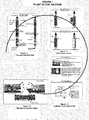
- Figure 1A shows the block diagram of the "ZERO EMISSION AST-CNR/ITM SYSTEM" constructed for being connected to a coal dust thermo-electrical plant (main plant), but it may be easily adapted by the man skilled in the art according to the following instructions to other industrial plants that operate using fossil fuels.
- the diagram in Figure 1 consists of blocks 1.1, 1.2 1.3 and 1.4, that show the fundamental treatment steps and the basic plant elements that starting from the flue gas coming from the main plant, lead to the production of methanol using only what is produced in the plant in terms and in the form of production waste, which would otherwise be disposed of, with considerable increase in terms of management of the main plant, especially because most of the times it is disposal of special and highly pollutant waste.
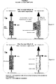
- Figure 2 shows block 1.1 of Figure 1 , that schematically shows the first three sections of the reaction tower of the vertical element A, wherein there are conveyed the raw flue gas coming from the boiler of the electrostatic precipitator of the thermo-electrical plant, located upstream of the modular plant of the invention. Said gas is conveyed to a duct that axially crosses the various sections of the tower to be treated in the following sequence:
- Figure 3 shows block 1.2 of Figure 1 , which relates to the fourth section of the reaction tower, where there occurs the separation between CO 2 and the nitrogen contained in the already washed flue gas coming from the previous section.
- the separation may typically occur with different methods, which implies different setup of the sections:
- the amines are returned to circulation and CO 2 is delivered to subsequent treatments.
- FIG 4 shows block 1.3 of Figure 1 , wherein there are shown the means used by the AST-CNR/ITM system for carrying out the hydrogen production, required for the methanol synthesis starting from H 2 and CO 2 .
- a suitably sized electrolyser plant will be required (an amount of hydrogen equal to 161 ton/h is required for the complete transformation of the CO 2 produced by the combustion of coal -600.00 Nm 3 /h).
- Electrolysers that may be used may be of the following type:
- thermo-electrical plant takes place using also the sulphuric acid produced by the desulphurisation of the gas and whose contribution, in terms of hydrogen produced, is about 0.55% of the overall requirement per each percentage point of sulphur contained in the fossil fuel or coal. This stage is carried out in an additional plant section with iron dust, as described below.
- Figure 5 shows block 1.4 of Figure 1 , wherein there are shown the means used by the AST-CNR/ITM system for carrying out the methanol production.
- Figure 5.4 schematically shows the methanol production diagram that uses membrane reactors to conduct the catalysis between H 2 and CO 2 for producing methanol.
- Figure 6 shows various types of setups, according to the type of main plant the modular plant of the invention shall be connected to. Note that each section may be separated from the others to which it is connected to and is constructed so as to be inspectable and/or repairable separately.
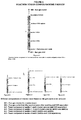
- Figure 6.1 schematically shows a first embodiment of a reaction tower A divided into four sections, three for removing the pollutants: the first at the bottom, for particulate matter and metals, the second for SOx (desulphurisation or deSOx) and the third for NOx (denitrifying or deNOx) and finally, the fourth, on top, for CO 2 capture. All the sections, and thereby all the tower, are prefabricated, can be made in workshop, assembled and fitted with all the utilities, wired and tested at the workshop, prior to transport on site for their erection.
- the tower is provided with a central main duct that crosses it axially, wherein the gas flows and entering from the bottom in 601 they cross each of the sections to be treated therein, and come out from the top in 602 after washing and separation from CO 2 .
- Each section is provided with inlet and outlet ducts (not shown) for the inlet of reagents and the outlet of the effluents to be treated in complementary plants (not shown) with outlet of the end products (as shown in Figure 2 ).
- Each section is connected to the previous one and to the next one by opening and sealed connecting means.
- Figures 6.2, 6.3, 6.4 and 6.5 shows further embodiments of tower A based on different ways of combining the different pollutant removal sections (from the first to the fourth), thus realising different reaction towers suitable for the different requirements of production plants.
- Figure 6.2 indicates the tower composed of sections 1° and 4° (metal removal and CO 2 separation);
- Figure 6.3 indicates the tower composed of sections 1°, 2° and 3° (metal removal, deSOx and deNOx);
- Figure 6.4 indicates the tower composed of sections 2° and 3° (deSOx and deNOx);
- Figure 6.5 indicates the tower composed of sections 3° and 4° (deNOx and CO 2 separation).
- the plant of the invention is adaptable to any other already existing plant, as it can be perfectly integrated with pre-existing structures in plants that require being upgraded/improved/modified to adjust to increasingly stricter anti-pollution standards.
- Figure 7 schematically shows the unitary plant module in plan view ( Figure 7.1 ), front view ( Figure 7.2 ) and in perspective ( Figure 7.3 ).
- the unit module may also have the function of a pilot plant in scale 1:1 for the tests to be carried out in the plants to be reclaimed.
- Figure 8 shows the assembly diagram of the reaction towers. Like the reaction towers, also the bearing structure is prefabricated at the workshop and can be assembled on site.
- Figure 8.1 shows the flue gas distribution plant diagram, inserted at the base of the bearing structure.
- Figure 8.2 shows the erection of the bearing structure of the three tower module, made with broad flanged beams 820 on the support base 821;
- Figure 8.3 shows the assembly of the prefabricated floors 830 and
- Figure 8.4 shows the assembly in this case of three reaction towers A.
- each flue gas duct (they are generally two as the towers are usually arranged on two facing rows, as per Figures 18 and 19 ) at the height of the branching that sends the gas to the groups of 3 reaction towers and at the beginning of the service duct for the 3 towers, there is another motor-driven gate for starting up or excluding the group of three towers. Opening or closing the gas distribution towers is controlled by software, which automatically opens the inlet gates to the groups of 3 towers based on the amount of gas produced in the plant and sensed by the various sensors placed in the duct. This is better illustrated in Figures 18 and 19 (plant with 12 and 60 towers respectively, organised by threes in two facing rows).
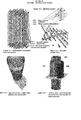
- Figure 9 shows in Figure 9.1 the front of the first section of the reaction tower.
- Such section has a substantially cylindrical shape, preferably with diameter of 2400 mm and height of 8500 mm and is sized for withstanding a pressure of 5 bars. It comprises a device for the treatment of mercury and heavy metals and a device for the electrostatic removal of fine particulates (ESP).
- ESP fine particulates
- Figure 10 shows further construction details of section 1 of the reaction tower.
- Figure 10.1 shows the AST electrode plant with the system for locking the electrodes to the tube bundle and with the electrical supply system.
- the respective electrode systems are removed therealong, which are fixed to the tube bundle so as to prevent the same electrodes from moving and colliding against the alveolar walls, thus causing damages to the plant.
- Safety measure the movement or release of an electrode automatically causes the interruption of the current flow to the electrodes to prevent possible damages to the plant. The same happens prior to opening the tube bundle washing system.
- Figures 10.2 and 10.3 respectively show a plan view and a perspective view of the sprinkler plants of the section. In this case, the washing is carried out by 38 sprinklers.
- the washing water is collected in the storage tank formed in the lower portion of the section and whose vertical walls consist of the skirt and of the flue gas inlet duct, whereas the bottom consists of the bottom of the section. It is open at the top and the washing water gathers therein by fall.
- An umbrella prevents the washing water from falling into the gas duct and further ensures a turbulent motion to the gas to ensure a better contact between the flue gas and the washing water.
- Floats and pressure sensors prevent the washing water from overflowing into the flue gas duct, starting recirculation (not indicated in the Figure) or start up pumps for the complementary plants (not indicated in the Figure) for the effluent treatment.
- the tank capacity typically is about 2.50 m 3 .
- This device allows operations for repairing and maintaining the sections without needing to disassemble the entire reaction tower.
- the sections may be opened for carrying out facilitated operations of assembly, inspection, repair, and maintenance, as is shown in the figure.
- Figure 10.4 shows the WESP AST in a perspective top view, with the alveolar tube bundle already equipped with the electrode plant.
- FIG 11 shows, again for the same section 1°, the reactor for the removal of mercury.
- the figure schematically shows an AST reactor, both in transparent axonometry of the entire first section ( Figure 11.1 ) and only of the part relating to the mercury removal reactor ( Figure 11.2 ), placed inside the first section and used also for removing other metals contained in the flue gas.
- a solution of mercuric chloride containing HgCl 2 is circulated in a tower consisting of a plurality of concentric porous ceramic rings ( Figure 11.4 ) soaked in mercuric chloride.
- the process flue gases which contain the mercury pass through the gas inlet duct and longitudinally cross the ceramic ring tower ( Figure 11.4 ) and here, the mercury contained in the gases reacts with the mercuric chloride to produce mercurous chloride.
- the mercurous chloride is insoluble and precipitates in the container of the solution arranged at the bottom of the reactor.
- the flue gas flow circulates inside the ceramic ring tower, crosses them and leaves the reactor through the side holes that carry the gas flow to the remainder of the section.
- the clarified solution contained in the tank overflows into the next tank side by side, where the concentration of mercurous chloride is lower, more mercurous chloride is added and such solution is pumped to the reagent ceramic tower to start the cycle.
- the solids that collect onto the bottom of the tank/primary decanter flow to the secondary decanter.
- zinc powder can be added to promote precipitation of the mercury from the solution.
- the solids of the secondary decanter are discharged in deposits (not shown) from which they are sent either for sale or to other manufacturing. All the operations are programmed and automated. Liquids are handled by pumps and the solids are discharged by hoppers with motor driven opening and discharge.
- Figure 12 schematically shows the front view ( Figure 12.1 ) of the second section of the AST-CNR/ITM reaction tower for SOx treatment.
- the SO 2 contained in the flue gas is adsorbed on an absorbent which is then regenerated, releasing liquid SO 2 , or sulphuric acid (H 2 SO 4 ) or finally, pure sulphur.
- FIG. 122 The schematic perspective view of Figure 12.2 shows the absorbing elements 1222, 1224, and 1226 that make up the second section of the AST-CNR/ITM reaction tower for the SOx removal.
- Solid supports are contained therein which are drizzled with water containing amine, typically dipropylamine (DPA), with the sprinkler devices 1221, 1223 and 1225, placed on top of the trays.
- DPA dipropylamine
- the flue gas coming from the first section after undergoing an adiabatic process and the saturation in H 2 O of the gaseous current, is subject to the particulates precipitation with wet electrofilters (tube bundles).
- This treatment (not present in traditional plants) is used in the AST-CNR/ITM system to ensure that the conversion processes for the production of SO 2 are not negatively affected by the presence of powders that could impair the catalyst activity.
- the ancillary plants in this section comprise a reactor and a filter/press for realising a neutralisation stage with limestone of the bleed extracted from the circulation.
- Figure 12.3 shows the operating diagram of the elements of Figure 12.2 .
- Figure 13 schematically shows the third section of the reaction tower AST-CNR/ITM designed for denitrifying.
- Figure 13.1 is the schematic front view of the third section for denitrifying of the flue gas in the reaction towers AST-CNR/ITM.
- the flue gas is fed to the section through the central duct 1310, and passing through the tanks, it is placed in contact with the liquids sprayed by the sprinklers.
- a device is used to obtain the equimolar ratio: a share of the solution circulating in the NOx section is sent, in the ancillary plants and complementary to the reaction tower, to a reactor (RA1) (not shown) wherein the ammonium nitrate is dissolved with H 2 SO 4 and in suitable temperature and pressure conditions it is converted into NO 2 .
- the nitrogen oxide gas by about 50% is recombined into the current of flue gas coming out of the SOx section to adjust the NO/NO 2 ratio to values close to the unit and the balance NO 2 is sent to the complementary unit HNE (not shown) wherein the conversion into HNO 3 takes place, along with the subsequent absorption for the production of solutions of commercial nitric acid (65%).
- a circulation of NO 2 is set between the NOx tower and the complementary reactor RA1, which is the process core.
- the reagent circulating into the sprinkler plants of the section is a NH 3 solution.
- the non reacted part (about 10%) of SOx is removed in the first part of the section.
- Figure 14 is a schematic front view of the fourth section of the reaction tower AST-CNR/ITM designed for CO 2 capture.
- This section is designed for absorbing and capturing the CO 2 by amine compounds kept in solution with water and sprayed by sprinkler plants 146 and 148 on the flue gas coming from the previous section and fed to the fourth section through the central inlet duct 141.
- Tank 144 is formed in the lower portion of the section and whose vertical walls consist of skirt 140 and of the flue gas inlet duct 141, whereas the bottom consists of the bottom of the section. It is open at the top and the amine solution gathers therein by fall. An umbrella prevents the amine solution from falling into the gas duct and further ensures a turbulent motion to the gas to ensure a better contact between the flue gas and the solution. Floats and pressure sensors prevent the solution from overflowing into the flue gas duct, starting the pumps (not shown in the Figure) that bring the solution rich in CO 2 into the stripping tower.
- the tank capacity typically is about 1.750 m 3 .
- the amine liquid is heated by the coil heat exchanger 145 with vapour supplied by complementary equipment (not shown) releasing the CO 2 , previously absorbed, which is removed by duct 142, and regenerating the adsorption solution that is transferred by pumps to the complementary plant tank (not shown) for feeding of the plants.
- the CO 2 is collected in special tanks for further use.
- Figure 15 is the simplified diagram of a CO 2 separation unit with membrane equipment.
- This membrane solution is an alternative to the separation described previously in Figure 14 of the fourth section of the AST reaction towers (which takes place with the amines) and is a novelty and peculiarity of the AST-CNR/ITM system.
- a gaseous current (flue gas) is taken into consideration with a flow of 4600000 Nm 3 /h, and is basically made up of nitrogen, watery vapour and carbon dioxide since in the treatments previously described the pollutants were removed in the following concentrations: CO 2 : 14% N 2 : 86%
- the aim is to obtain a gaseous current rich in CO 2 by the use of membranes.
- Some types of ceramic and polymeric membranes are taken into account below and a computation code was used to predict the level of separation of carbon dioxide based on the important design parameters such as the stage cut, the pressure ratio and the required membrane surface.
- the flue gas path is that of Figure 15 , wherein the gas represents the supply N 2 +CO 2 ) and the final part of the treatment is represented by the effluents of the third membrane module (3 passages of gas into the membrane modules): CO 2 and N 2 .
- CO 2 is sent to the storage zone prior to its use, after having undergone a compression process that will raise the CO 2 pressure to 50 bars.
- the process, described hereinafter, is an innovative process and to the inventors' knowledge there are no other plants that use the membrane thus used for separating the CO 2 from the flue gas.
- FIG 16 shows the diagram of the AST plant for the hydrogen production through the thermochemical splitting of water.
- This hydrogen production method by means of HTR reactors was first studied by the DOE (Department of Energy) ordered in the Seventies to the General Atomics, Sandia National Laboratories, and to the University of Kentucky which identified as many as 115 possible processes.
- thermo-chemical cycle to obtain the splitting of water, thus converting the heat supplied into chemical energy (with a given yield function of the selected cycle and of the machinery that performs it).
- the only reagent used is water, which is splitted into 3 stages by heat, providing oxygen and hydrogen; all the other reagents are fully recycled (thereby without generating harmful effluents for the environment).
- the reaction diagram of the cycle is as follows H 2 SO 4 ⁇ SO 2 + H 2 O + 1 ⁇ 2O 2 (850°C) I 2 + SO 2 + 2H 2 O ⁇ 2HI + H 2 SO 4 (120°C) 2HI ⁇ I 2 + H 2 (450°C) H 2 O ⁇ H 2 + 1 ⁇ 2O 2 and it is divided into three main steps:
- Process by-product is the heat at the temperature of about 100°C, in turn usable for other applications (for example, remote heating).
- thermo-electrical plant of 1320 MWel burns 3,500,000 tons coal in one year, the ashes produced sum up to about 15%, every year the thermo-electrical plant therefore produces 525,000 tons ashes that can all be sent for sale, greatly improving the central profitability.
- a further difference made by AST was to replace helium gas with CO 2 (present in the AST system 163) in the high temperature ceramic exchanger 165 for the cycle S-I.
- FIG 17 Schematic view of a reactor with 82 membranes AST-CNR/ITM for the production of methanol from the synthesis of CO 2 and H 2 .
- the reactor was designed by AST-CNR/ITM and it is shown in Figure 17.1 .
- Figure 17.3 shows the perspective view of the pack of 82 ceramic membranes of the AST-CNR/ITM reactor for methanol production and Figure 17.2 is the view of the trays required for aligning the membranes and equally distributing and keeping on site the catalyst.
- the membrane bundle kept together by 6 spacing plates, globally shows the base module for the ceramic membrane reactors AST-CNR/ITM.
- Figure 17.4 shows the operating diagram of the reactor. Calculations and drawings are valid and confirmed; they are based on laboratory experience. The operating pressure was brought to 50 bars and thereby, the membrane reactor was designed in detail, which has an inner diameter of 400 mm and with 82 membranes having the inner diameter of 20 mm with catalyst outside the membrane.
- the reactor at 50 bars produces 1230 kg/h methanol circulating 1158 m 3 /h CO 2 and 3500 m 3 /h H 2 (with excess of H 2 ).
- An outflow tube for the methanol is thus required which starts from the second section with 200 mm diameter, in any case typically suitable for preventing excessive turbulence phenomena.
- Table 1 further shows the most important data of the methanol production with different membrane reactors.
- Table 1 Number and type of membrane reactors required to transform all the CO 2 contained in the flue gas of a 1320 MW coal dust thermo-electrical plant into methanol.
- Membrane reactor Num. membr. 020 mm Inlet of CO 2 Kg/h Inlet of H 2 Kg/h Catalyst. Kg/react.
- the copper oxide catalysts which had been a little difficult to use, were considerably improved by Synetix, which developed a new process at low pressure which operates at 35-55 bar and 200-300°C, becoming the most widely used one.
- the catalysts used for the synthesis of methanol are based on copper. Many techniques have been developed to stabilize the catalysts. Highly active and selective catalysts suitable for large production of methanol today are those incorporating Cu/ZnO/AI 2 O 3 . These catalysts are already active at 200°C and selective for the formation of H 2 and CO 2 .
- MRs membrane reactors
- a membrane reactor can be used for the synthesis of methanol in different ways.
- the first method is that of utilizing dense membranes of palladium to feed the hydrogen in a controlled manner into the reaction environment and avoid its subsequent separation.
- the membrane reactor has the purpose of continuously removing from the reaction environment one or more products to improve the conversions for passage and extract the pure product or products.
- literature there are works that describe the use of MRs for the production of methanol.
- Table 2 gives the best results obtained from various authors with the MRs compared to the traditional ones. Table 2. Improvements obtained by using MRs in the production of methanol. Membranes Results compared to TR References Lithiated Nafion 40% improvement in the yield in Methanol [1] Pd--Ag 9% improvement in the conversion at balance [2] Lithiated Nafion 40% improvement in the yield in Methanol [3] Silicone rubber/ceramic 22% improvement in the conversion [4] Zeolite MOR/ZSM--5/chabazite 60% improvement in the conversion [5] Zeolite A--type 132% improvement in the conversion [6]
- the self-supported zeolitic membranes are extremely fragile. In consideration of this, it is necessary to use supports (alumina, stainless steel) on which zeolitic layers are grown to obtain the desired mechanical resistance. However, their use at the industrial level is highly limited by problems of reproducibility in the preparation stage [8] and presence of intracrystalline defects in the zeolitic layer [10].
- the ratio of H 2 /CO 2 supply for the reaction is 3/1 in molar (and volumetric) terms. So that the requirement of H 2 is 1,800,000 Nm 3 /h equal to 161 ton/h of hydrogen.
- FIG. 18 Plan view 18.1 and perspective view 18.2 of the AST-CNR/ITM plant for a coal dust thermo-electrical plant of 300-:-350 MWel.
- the module is made up of 12 reaction towers connected by the flue gas distribution system 181 which, captured by the duct of flue gases of the plant is distributed for processing to the towers through motorized gates commanded by the general control of the plant.
- the layout typically has dimensions of 24.00 x 14.00 meters and has available 9 storeys for a total of 3,024 m 2 of useful surface, where the complementary installations are allocated for the processing and collection of polluting material, and a dead freight volume of 110,000 m 3 .
- the plant made up of twelve reaction towers, is capable of processing between 1,100,00 and 1,300,000 m 3 of dry flue gases (scfm-dry) corresponding to the emissions of a supercritical coal dust thermo-electrical plant with power of 300-:-350 MWel that are the average sizes of the unit modules for thermo-electrical plants in Europe and the USA respectively.
- FIG 19 Plan view ( Figure 19.1 ), front view ( Figure 19.2 ) and perspective view ( Figure 19.3 ) of the AST-CNR/ITM plant for a coal dust thermo-electrical plant of 1320 MWel made up of 60 reaction towers designed for the supercritical coal dust thermo-electrical plant of AST SERBIA.
- the plan has dimensions of 120.00 x 14.00 meters for a building volume of 62,000 m 3 , arranged on 9 storeys for a total of 9,500 m 2 where the complementary plants are allocated for the processing and collection of the polluting materials.
- the plant made up of sixty reaction towers, is capable of processing 4,800,000 m 3 /h of dry flue gas (scfm-dry) corresponding to the emissions of a supercritical coal dust thermo-electrical plant with power of 1,320 MWel.
- the modular plant for removing the pollutants from flue gases produced by industrial processes according to this invention which makes up the so-called "AST-CNR/ITM system" at zero emission for the treatment of flue gases is composed of prefabricated modular elements, with programmed and automatic operation, which form the different sections of the reactions towers.
- the membrane reactors for the production of methanol of AST-CNR/ITM design also form part of the plant as will be explained hereinafter also with the use of the attached figures.
- the towers are also prefabricated and modular with automatic operation, and are used for the removal of pollutants (such as NOx, SOx, submicron particulates, heavy metals, in particular mercury) and for the capture of CO 2 from the flue gases which form during combustion of fossil fuels in the plants that in their processes use these types of fuels, such as:
- pollutants such as NOx, SOx, submicron particulates, heavy metals, in particular mercury
- the plant according to the invention includes electrolysers of per se known type, such as for example those marketed by the SIEMENS and GENERAL ELECTRIC companies, necessary for the production of hydrogen and oxygen.
- FIG. 1A The block diagram of Figures 1 and 1A shows the processes of the "ZERO EMISSION AST-CNR/ITM SYSTEM".
- the "AST-CNR/ITM" process overall includes four types of integrated treatments, the first one relative to flue gas treatment, the second to the separation of the CO 2 from the flue gas, the third to the production of hydrogen and oxygen by electrolysis at high temperature and thermo-chemical water splitting, the fourth to the production of methanol starting from the CO 2 .
- the flue gas treatment is based on processes of chemical conversion, absorption (chemical-physical process consisting in the adhesion and concentration of the substances dissolved or dispersed into the atmosphere on the surface of a body), oxidation of the combustion gas components, and corresponding combinations. All these processes occur in the left columns of the block diagram of Figure 1A , where each of the boxes represents a section of the reaction tower, illustrated also in Figures 18 and 19 . These treatments are conducted on the flue gas withdrawn from the ducts that carry said flue gas, treated in advance in the electrostatic precipitator of the plant, to other plants or to the chimney.
- the base module AST-CNR/ITM is made up of a reaction tower A constituted by four sections ( Figure 6.1 ) formed by cylinders preferably having a diameter of 2.40-:-2.50 m and a height of about 8.50 m.
- the sections are arranged vertically one on top of the other and inside they have a principal central duct inside which the flue gas passes and in which the pollutants are removed or captured, with dry or damp procedures and the use of appropriate catalysts.
- the sections are the following:
- Each tower A can typically have the following dimensions: diameter 2.40 m and height 34.00 m, can treat 70,000 m 3 /h of dry flue gas (scfm-dry) or 125,000 m 3 /h of wet flue gas (acfm-wet).
- Each tower and each section are connected to the next ones through pipes that typically can have a diameter of around 0.75 m, provided with shut-off valves and/or fans per se known.
- the reaction towers A can be set up differently depending on the requirements of the plants that must be treated and for each of which will studied the most appropriate measures.
- Figure 6 illustrates some example of the types of assembly of the towers as a function of the nature of the flue gas, whose treatment depends:
- the disposal plants according to the invention have been designed in order to be built, assembled and tested in the respective construction factories to then be dismantled and shipped on roads and railways, thanks for their dimensions, kept within the limits of the shapes permitted.
- the reaction towers A can operate with pressures up to 5 bar and this allows great savings in the construction phase because the base element will be able to treat quantities of flue gas more than double compared to the 70,000 Nm 3 /h provided for in the base element operating up to 2 bar. If the towers operate at pressures of 5 bar they can treat in the base element more than 150,000 Nm 3 /h and therefore the plants will be reduced since only half of the reaction towers will be needed to treat equal quantities of flue gas and moreover its maintenance will be simpler and less expensive.
- the towers are connected among them at inlet down low and on outlet up high through pipes that carry the flue gas to be treated and distributes them to the individual towers and collects them top-edge, once treated, to convey them to the outlet of the plant.
- each section is provided with inlet pipes/ducts (not shown) for the reagents and outlet pipes/ducts (not shown) for the removal and/or recirculation of eventual final products.
- the bearing structure of the reaction towers A represented in Figures 8.2, 8.3 and 8.4 , is made with erected frames, calculated to support, in addition to the permanent loads of the structure itself and the technical equipment, also the loads from the accumulation of reagents and materials resulting from the process, and the loads transmitted by the people who work in the plant.
- the sizing is within the capacity of the man skilled in the art.
- Frames 820 are made with beams and pillars created with broad flanged beams of commercial steel, assembled in the workshop in sections with shapes in sizes that can be transported normally, in order to reduce to a minimum the building operations.
- the structure has the peculiarity of allowing the replacement of a section of the reaction tower A, whatever its position in tower A, without having to dismantle the entire reaction tower.
- the set up allows the removal of a single section, for repairing, and its substitution with another section ready and available in house, without the operation requiring the elimination of the flue gas from the circuit, of an entire module of the plant. It is therefore possible to exclude a single tower from the operation of the plant without stopping it.
- the section removed can be substituted with another similar section, that will be available at the plant, sending the removed one to the construction factory for its overhaul. This possibility makes the plant much more reliable and less expensive since it can guarantee the operation of the plant for all the 8,760 hours available per year, and can program a maintenance which excludes in turn one or two reaction towers from the process.
- the assembling of the reaction towers takes place according to conditions per se known, by setting up the foundations of the structure and the connections with the duct of the gas flue, with the networks of the utilities and controls. Then the assembling of the bearing structure described above is done, which arrives at the building site already assembled in sections normally transportable, treated for protection against corrosion with special galvanizing and paints. The assembling is done with welded flanges. Then the prefabricated floors are assembled, the sections of the tower are put in place, the complementary equipment and accessory machinery are mounted and finally the wiring for the connection of the controls of the individual sections of each tower is done, and that of the different towers with the general control of the plant according to a hierarchical system.
- the data control and acquisition system of the sections of the reaction towers permits the automatic performance of the zero calibration measurements and the safety procedures.
- the status of the system and the individual devices is displayed on a panel, on the displays in the control room and can be checked in real time from any position through the network.
- the processing system and the presentation of the data can be easily configured and managed by the operator.
- the acquisition of the data from the field, its validation, the processing and presentation of the hourly, daily, weekly and monthly averages are done in accordance with current regulations.
- the system gives in real time the capacity flow of the flue gas, their temperature and the contents in CO, CO 2 , O 2 , SOx, NOx, particulates and metals.
- the program of management takes care of putting into operation the number of reaction towers capable of handling the total cleaning of the flue gas.
- the program of management of the plant also takes care of managing and organizing a turnover of work for the reaction towers, in order to organize an equal management of work for all the towers and therefore create a system of equal wear on the towers.
- the FT-IR dual cell process control (known per se) is characterized in that the output signal from the interferometer is split in two optic paths and sent to two different cells.
- the sample of gas taken respectively upstream and downstream the removal system is then sent to them.
- a detector is assigned to each cell, the analysis is done automatically and simultaneously by the two withdrawal points.
- the first section of the AST-CNR/ITM reaction towers is equipped for the elimination of mercury and other metals, after removal of the fine particulates.
- the solids are captured with an electrostatic precipitator, also called ESP, of the wet type (indicated as WESP-Wet ElectroStatic Precipitator) together with the oxides of heavy metals, fluorides and chlorides.
- ESP electrostatic precipitator
- WESP-Wet ElectroStatic Precipitator the wet type
- the remaining water is treated in an ion exchanger with caustic soda to eliminate the chlorides and is recycled again inside the water treatment system using membrane plants.
- the operation of the WESP is influenced by the temperature of the flue gas which determines the electric characteristics that the electrodes must have for the corona effect to start and the pollutants to precipitate. For a given applied voltage, the dispersion current increases with the rise in temperature.
- the temperature of the flue gas which enters the WESP is controlled and is generally quite constant.
- the temperature of the flue gas is controlled by the temperature of the water of the plant which can be modified to improve the performance of WESP.
- the composition of the flue gas determines furthermore the electric characteristics of the WESP.
- the composition of the flue gas varies during the use of the WESP, it is instantly evaluated by the control system so that the electric characteristics of the WESP are also modified instantly to guarantee its perfect operation.
- the pollutants are present in the following forms: Impurities Form of impurity chemical formula Fluoride Powder HF Chloride Powder HCl Arsenic Oxide, element As 2 O 3 , As Selenium Oxide, element SeO, Se Mercury Element Hg Zinc Sulphate ZhSO 4 Lead Sulphate, element PbSO 4, Pb Copper Sulphate CuSO 4
- Acid fog, copper, nickel and iron and the acids are generally considered easy to collect.
- the more difficult impurities include zinc, lead, arsenic and antimony.
- the flue gases in other words the combustion gases, which enter the first section of the reaction tower at a temperature of approximately 170°C, are saturated and cooled through a heat recovery system and with the injection of the process water.
- Figure 9.2 is a transparent axonometry of the first section, with particular reference to the West-ESP (wet).
- the flue gases entering from the bottom pass through a heat exchanger, in fact, to avoid their having a high degree of humidity, they undergo cooling through a heat exchanger, coil-type for example, which lowers the temperature from 190-:-170°C to 50-:-40 °C.
- the flue gases are then taken by pipes 931 and 932 where they are subjected to an electric field.
- the AST-CNR/ITM electrostatic precipitators have a high efficiency in blocking the submicron particles and use electrostatic forces to remove the particles suspended in the flow of the flue gas.
- the operation of the AST-CNR/ITM precipitators includes the following stages:
- the speed of the flue gas inside the ESP is measured in such a way as to reduce the risk of dragging solid particles which have accumulated on the collection plates, constituted by the walls of the tube bundle.
- the ESP AST-CNR/ITM are characterized by the low amounts of load losses due to the particular processing of the electrodes which facilitate the onset of the corona effect at lower kV which vary in general between 20 and 100 Pa.
- the electrodes and the piping are washed periodically by a programmed system that blocks the supply of electricity in the electrodes and at the same time opens the supply circuit of the sprinklers which spray water for the washing of the electrodes and the piping, thus removing the accumulated particles.
- the ESPs AST-CRN/ITM is used for the removal of the free flow particles (that is, the particles contained in the flue gases before the first washing in the first section of the reaction tower) and is taken in the first section to the wet ESP. It is made up of a washing plant to block the VOCs.
- the liquid is the one coming from the washing of the WESP specified above, usually made up of water and detergents, and continuously removes the particles.
- the wet ESPs is always in operation. It is widely used for applications where the gas to be treated is hot, has a high humidity content and contains sticky or submicron particles that cannot be treated with other methods.
- the WET-ESP section of AST-CNR/ITM illustrated in Figure 9.2 in transparent axonometry, includes significant improvements in technology for the efficiency of operation when in the pollutants to be removed from the flue gases mercury and its compounds are present.
- the honeycomb configuration of the electrostatic precipitator ( Figures 9.2 and 9.3 ) is advantageously formed by a circular configuration so that the piping in this case is made up of side by side pipes.
- the arrangement of the electrodes remains basically the "multipoint" one of Figure 10.1 and no interruption of operation that is not programmed is required for cleaning.
- coal contains traces of mercury as contaminant.
- mercury volatilizes as mercury vapour and mixes with the flue gases.
- the coal also contains selenium it is released, during combustion, together with the mercury forming HgSe and both can be easily removed from the flue gases in the wet-ESP, to then be sent to the other sections for removal of other pollutants.
- the mercury sulphate will also be easily removed from the flue gases in the wet-ESP before the electrostatic precipitation phase.
- the mercury that remains free goes on along the reaction tower as mercury vapour.
- mercury enters in the section of the reaction tower where the removal of SOx occurs, thus contaminating the sulphur and the calcium sulphate (chalk) which are obtained as products of the removal of the SOx.
- the sulphur contaminated with mercury cannot be used in industries whose products enter the feed cycle: consequently, it is preferable to remove the mercury from the sulphur to obtain a product better marketable and this must always be performed in the first section of the reaction tower.
- Mercury can be treated while it is in the flue gas with the method of removal in gaseous phase (known as Outokumpu process). It is advantageous to remove mercury in the first section of the reaction tower in that it highly reduces the probability of polluting the other products obtained in the subsequent treatments performer in the reaction tower (sulphur, chalk, etc.), which can be profitably reused as secondary raw materials.
- the mercury gas and the other metals are captured with H 2 SO 4 in the amount of 80-90% at a temperature of 150-180°C.
- the acid is recycled until the solution is not saturated with HgSO 4 and precipitation starts.
- the HgSO 4 crystals are then separated in a thickener (not shown).
- a thickener not shown
- other polluting agents besides mercury are removed from the flue gas.
- the solids collected in the thickener can contain iron, zinc, copper, selenium, etc.
- Mercury can be recovered by mixing first the solids precipitated with calcium oxide and then by heating the mixture to distil and separate the mercury.
- the selenium remains in the mixture in form of calcium selenite (these phases occur in complementary plants).
- the selenium oxide in water gives selenious acid.
- the selenious acid is produced with this reaction also during washing with water of the flue gases of selenium dioxide which evolved during the treatment of the anode sludge of electrolysis of the copper.
- the temperature of the solution must be maintained at 25-:-30°C so that the selenium deposits as sludge in a form that can be easily discharged from the precipitators. Beyond this range of temperature, the mud becomes plastic and is difficult to remove. The mud produced is then boiled to coagulate the amorphous red selenium and to convert to crystalline form.
- the solutions of selenious acid contain tellurium. In the presence of sulphuric acid, the precipitation of selenium is selective. Instead in the presence of hydrochloric acid the tellurium also precipitates and, at high concentrations of hydrochloric acid, both the metals dissolve forming chlorides.
- the salts deriving from it are the selenites.
- the red amorphous selenium reacts with the mercury of the flue gas forming HgSe, mercury selenide.
- the contact time in the filter is approximately 1-2 seconds.
- the filter continues to be effective until the level of mercury in the filter reaches 10-15%.
- the filter then is treated to recovery the mercury and to regenerate the selenium.
- the filter will remove approximately 90% of the mercury received.
- This process of removal depends on the presence of elementary amorphous selenium to react with the elementary mercury in the gas.
- the concentration of the selenious acid is between 20 and 40%. The lower concentrations of selenium will create highly soluble residues of the selenium and the sulphur which make them inefficient in the reaction with the mercury in the gas.
- the supply of oxidation of the acid will cause the dioxide or the selenite of the selenium which has formed. If the flue gas that is treated contains sufficient selenium, it is not a requirement to add the selenium to the solution of the washing plant.
- the washing plant of the selenium is suited to removing the large relative quantities of mercury in the flue gas and has an efficiency of about 90%.
- honeycomb tubing is used as described in the beginning and illustrated in Figure 11 .
- This process is based on the oxidation of the mercury vapour contained in the flue gases with mercury chloride to create mercurous chloride according to the reaction: HgCl 2 + Hg ⁇ Hg 2 Cl 2
- a solution of mercuric chloride containing sufficient quantity of HgCl 2 is circulated in a tower of various porous ceramic rings soaked in mercuric chloride.
- the process flue gases which contain the mercury pass through the ceramic tower where the mercury reacts with the mercuric chloride to create mercurous chloride.
- the mercurous chloride is insoluble and precipitates in the solution. From the main circulating flow of the ceramic tower a lateral flow is separated (not shown) aimed towards the primary decanter (not shown) where the mercurous chloride is deposited in the lower part of a tank (not shown).
- the clarified solution spills over again to the tank and is pumped to the reagent tower.
- the solids collected from the bottom of the primary decanter flow to the secondary decanter (not shown) where the concentration of mercurous chloride is lower.
- zinc powder can be added to promote precipitation of the mercury from the solution.
- the solids of the secondary decanter are discharged in deposits (not shown) from which they are sent either for sale or to other manufacturing.
- the washing process removes the mercurous chloride from the solution. If the concentration of mercurous chloride is not kept within the parameters calculated it will become inefficient as reagent solution. To regenerate it, a part of the mercurous chloride collected will serve for the purpose.
- Figure 11 shows in detail the reactor for the mercury of Figure 9.2 .
- the flue gases in output from the collection plant of the particulate matter and before entering into the second section are washed in advance with a watery acid solution to eliminate HCI, HF and residual particulate matter without absorbing the SO 2 contained in the flue gas.
- the processes of desulphurization can be classified in processes with or without recovery.
- the products recovered are, depending on the cases, SO 2 , H 2 SO 4 , (NH 4 ) 2 SO 4 , NH 3 , CaSO 4 , H 2 .
- the processes without recovery are those that, by achieving the removal of the SO 2 through a reagent whose regeneration is not economically convenient, cause a consumption of reagent proportional to the quantity of SO 2 removed from the current of flue gas.
- These processes generally less expensive in the plant phase, present however the problem of disposal of considerable quantities of products resulting from the treatment, basically composed by a mixture of sulphites and sulphates in the form of mud or highly pollutant solid products.
- the processes with recovery are those that allow both the chemical or thermal regeneration of the absorbent for its reuse and the recovery of the SO 2 to obtain a marketable product such as liquid SO 2 , sulphur or H 2 SO 4 .
- the wet processes are based on the absorption of the SO 2 with a watery solution/suspension. These processes, characterized by a multiplicity of engineering choices inherent to the operating conditions, to the flow charts, to the type and concentration of the absorbent solution, are those that have had greater proliferation.
- the AST-CNR/ITM technology for the removal of the SOx is a Flue Gas Desulphurization (FGD). This method was selected to achieve a "system of zero emission" and is based on the utilization of what is contained in the flue gas for obtain a production of hydrogen necessary for the AST process.
- FGD Flue Gas Desulphurization
- the FGD systems represent an essential component of the thermo-electrical carbon plants, especially is of medium/high level of sulphur.
- the concentration of SO 2 (under normal conditions and with oxygen at 6%) in the flue gas produced by a steam generator supplied with a carbon having 3% of sulphur is equal to approximately 6000 mg/Nm 3 which, in order to fall within the regulatory limits valid for large plants (>200 mg/Nm 3 ) requires an efficiency of desulphurization of almost 97%.
- the wet, semi-wet and dry processes remove the SO 2 present in the gases burned through injection of a basic absorbent, in most cases based on calcium, and often simply represented by calcium carbonate.
- the regenerating and combined processes present the not negligible advantage of high efficiency in the removal of the SOx together with no consumption of limestone and the no production of solid residues.
- the sulphurous anhydride is eliminated by using an amine, typically dipropylamine (DPA), as additive through catalyzing washing trays 1222, 1224 and 1226 and with the extraction of the process water.
- DPA dipropylamine
- the trays contain solid supports (packs of ceramic elements) which are drizzled with water containing dipropylamine.
- the water is then removed and divided in a stripping column and in a cooling device of the gas, outside the reaction tower.
- the remaining gases are passed to the next section of the reaction tower, the third section.
- nitrogen oxides we generally mean all the nitrogen oxide and dioxide, even though in reality they constitute a more complex mixture as summarized in Table 4.
- Table 4 - Components of the nitrogen oxides Compound Formula Nitrogen dioxide N 2 O Nitrogen oxide NO Nitrogen dioxide (Nitrous anhydride) N 2 O 3 Nitrogen dioxide NO 2 Nitrogen tetroxide N 2 O 4 Nitrogen pentoxide (Nitric anhydride) N 2 O 5
- the small residual part of the sulphurous anhydride coming from the second section is converted in the third section ( Figure 13 ) of the reaction tower through catalyzing trays in them and by contact with the ammonia solution.
- the sulphate resulting from the contact of the ammonia with the flue gas is processed in the electrolysis.
- NO 2 is added in stoichiometric quantity to the gas mixture of NOx and is completely mixed by the circulation trays.
- the mixture of the NOx gas passes along a certain number of contact trays together with ammonia and is converted into ammonia nitrate.
- the nitrogen dioxide surplus can be converted with water into nitric acid in a stripping and reduced to nitrogen in a small adsorbent catalyst by using ammonia in the complementary plants.
- ammonia sulphate is the by-product of the electrolysis and is done in complementary plants in ammonia and sulphuric acid.
- the ammonia is the reactive in the third section of the tower.
- the sulphuric acid is used for the separation of the nitrate. When sulphuric acid is added to the ammonia nitrate, one gets nitrogen dioxide and ammonium sulphate.
- the concentration of the CO 2 depends on the type of fuel which generated the flue gas emitted and that, in percentage on the volume of the flue gas, varies from 14% for coal power plants, to 8% for natural gas power plants, to 4% for natural gas power plants with combined cycle and in other ratios for the other production plants.
- the CO 2 so captured is subsequently subjected to different processes according to the selected confinement or utilization type; however its shipment to a place other than where it was captured is provided, it is subjected to a pressurization process in order to pass from the gaseous state to the liquid state with consequent reduction of volumes.
- the fourth section is made up of an adsorption tower (MEA amine) in which the CO 2 is captured by aminic substances (MEA) which subsequently are put into a stripping tower where the heated aminic liquid releases the concentrated CO 2 regenerating the adsorption compound.
- MEA amine adsorption tower
- MEA aminic substances
- the CO 2 so captured can be subsequently subjected to various processes depending on the type of preselected confinement or utilization. For example, pressurization, or can be transformed in methanol as hereinafter described.
- the CO 2 is confined in repositories already exploited and exhausted of gas, oil or in marine depths.
- AST-CNR/ITM system of separation of the CO 2 by a gaseous current consisting of N 2 and CO 2 through membranes.
- This membrane solution is an alternative to the previously described amines separation in the fourth section of the AST-CNR/ITM reaction towers and illustrated in Figure 15 .
- a gaseous current (flue gas) is taken into consideration with a flow rate of 4600000 Nm 3 /h, and is basically made up of nitrogen, watery vapour and carbon dioxide since in the treatments previously described the pollutants were removed in the following concentrations: CO 2 : 14%, N 2 : 86%
- Some types of ceramic and polymeric membranes are taken into account below and a computation code was used to predict the level of separation of carbon dioxide based on the important design parameters such as the stage cut, the pressure ratio and the required membrane surface.
- the stage cut is defined as the ratio between the permeated capacity N p and the rate to be treated N 0 .
- the pressure ratio is defined as the ratio between pressure in the feed end (p I ) and pressure in the permeate end (p II ).
- the rate of permeated gas rich in CO 2 is equal to about 10% compared to the rate to be treated. In relation to the required purity level, of course it is possible to recirculate the rate in output from the separation unit mixing it to the gas to be treated, or treat it again in a subsequent unit.
- Table 7 shows the main results relating to membrane APS/MS/Al 2 O 3 S having selectivity equal to 800. It is seen, for example, that quite similar performance compared to the case of complete mixing flow can be achieved with a membrane surface equal to 400 m 2 . Table 7. Flow in equicurrent and ceramic membranes. p I /p II S(m 2 ) y p (%) x L (%) Stage cut (%) 20 400 98,6 8,8 10,15 30 400 98,4 5,4 13,47
- Membrane APS/MS/Al 2 O 3 H shows it achieves a purity degree ( y p ) clearly higher but a similar stage cut.
- Case III separation unit with polymeric membranes and flow type "equicurrent".
- a separation unit was considered, consisting of polymeric membranes the data of which are shown in Table 8 ( Baker, 2004). Table 8. Permeability in barrer (10 -10 cm 3 (STP) cm/cm 2 sPa) of some polymers. Gas Rubbers Glasses Silicone rubber at 25°C ( T g - 129°C) Natural rubber at 30 °C ( T g - 73 °C) Cellulose acetate at 25 °C ( T g 40 - 124°C) Polysulfone at 35 °C ( T g 186°C) Polyimide (Ube Industries) at 60 °C ( T g > 250 °C) H 2 550 41 24 14 50 He 300 31 33 13 40 O 2 500 23 1.6 1.4 3 N 2 250 9.4 0.33 0.25 0.6 CO 2 2700 153 10 5.6 13 CH 4 800 30 0.36 0.25 0.4 C 2 H ó 2100 - 0.20 - 0.08 C 3 H 8 3400 168 0.13 - 0.015 C 4 H
- the resulting CO 2 is then transformed into methanol according to one of the typical transformations, known to the man skilled in the art, starting from H 2 O electrolytically separated into H 2 and O 2 (in this way the problem of confining the CO 2 is solved), which is thus produced from scrap material rather than from oil origin fuels.
- Methanol may be produced following various processes. For example by a so-called low pressure process, which works at 35-55 bars and at 200-300 °C.
- Methanol currently is mainly produced as chemical reagent or solvent.
- the methanol market is expected to increase in view of the research on direct methanol fuel cell (DMFC) and on the methanol reformers for producing hydrogen.
- the catalysts used are all based on copper and the most active and steady one is based on Cu/ZnO/Al 2 O 3 .
- Table 9 shows the typical compositions of catalysts used for producing methanol from CO 2 and H 2 .
- Table 9 Composition of catalysts for the synthesis of methanol.
- Manufacturer Cu [%] Zn [%] Al [%] BASF 65-75 20-30 5-10 Süd Chemie 65-75 18-23 5-10 ICI 61 30 9 Du Pont 50 19 31 Haldor Tops ⁇ e 50-60 21-25 15-28
- a membrane reactor was designed in detail, with an inner diameter of 400 mm and with 82 membranes having the inner diameter of 20 mm with catalyst outside the membrane shown in Figure 17 , which shows the reactor with 82 membranes AST-CNR/ITM for the production of methanol from synthesis of CO 2 + H 2 .
- the dimensions of the membranes are typically of 1000 mm height, with inner hole of 20 mm diameter and wall thickness of 4 mm (thickness varies as the operating pressure varies).
- Figure 17 shows, besides the pack of the 82 membranes 177, also the spacing plates 175 with the indication of the holes 176 wherein the membranes are inserted.
- the catalyst of the reactor is placed in plates 175 of Figures 17.1 and 17.2 , which for this specific reactor is 107 kg; about 18 kg catalyst are therefore distributed in each plate. In its operating position, the reactor can be seen in Figure 17.4 .
- the central body of the reactor is set up with 1500 membranes and consists of 17 bundles of 82 membranes 1000 mm long, with inner diameter of 20 mm and wall thickness of 4 mm.
- the assembly of the membrane reactors has thus been made modular considering the one with 82 membranes as base module.
- the operating pressure is 50 bar.
- Methanol may be mixed with water in any proportion: mixing causes a volume shrinkage of the solution and releases heat. It is used as additive to fuels or it is used as a fuel itself, generally solid fuel (meta tablets).
- the main technologies for hydrogen production are:
- Such technologies differ both in the way the bond that links hydrogen to oxygen in water is separated by electrolysis and photo-electrolysis or to carbon in hydrocarbons and biomasses, and for the raw materials used to produce hydrogen.
- metal iron filling is reacted in an aqueous solution of sulphuric acid, obtaining iron sulphate and gaseous hydrogen that must then be dried, that is, freed from steam, according to the reaction Fe + H 2 SO 4 ⁇ FeSO 4 + H 2
- a part of the hydrogen required by the "system” may be produced using H 2 SO 4 obtained from the removal of pollutants from the flue gas.
- the electrolyser HYDROPURE SESPI selected by AST-CNR/ITM for the production of hydrogen required for methanol synthesis, is on the market.
- the hydrogen and oxygen produced are stored in 2 gas meters (not shown) respectively that allow constant feeding to the purification, drying and compression systems (not shown).
- the purification uses the catalytic systems (in se known) that allow the production of hydrogen at 99.999% purity.
- Membrane or dry piston compressors in se known) ensure a high gas purity.
- the gas "dew-point" is kept and controlled automatically to a dew point of about 60°C.
- This electric energy can be produced from renewable energy systems: wind, photovoltaic, hydroelectric or energy produced using the waste of caloric energy of the entire plant being treated.
- a technology that seems to be made ad hoc for the production of hydrogen is that of photovoltaic solar panels.
- thermo-electrical plants More suitable and advantageous is the production of hydrogen in thermo-electrical plants since the energy produced in excess in low requirement periods, especially in night hours, may be added to the energies listed above.
- the plant according to the present invention and the related reaction towers consist of modules sized so as to ensure transportability on road and railway since their dimensions are within the allowed limits without needing special authorisations for transport.
- the removal plants according to the invention may be used in thermo-electrical plants, refineries, incinerators.
- the modular elements may be replaced in short time without expensive plant stoppage.
- the reaction towers can operate with pressures up to 10 bars and allow great saving in the construction step for the reduced dimensions of the modules and in the maintenance step, made easier by the small size; moreover, they facilitate the upgrading of existing plants since the component modules are of reduced dimensions compared to those replaced and thus require less availability of space for their erection on site.
- the towers of the invention allow removing the pollutants so as to permit the elimination of all the polluting matters from the flue gases and the transformation in secondary raw materials such as to be sold, or commercially pure and reusable so as not to make further waste to be removed in other forms.
- the towers of the invention allow operating at "zero emissions” since it is possible to also capture the CO 2 and transform it into methanol, thus eliminating the problem of confining the CO 2 in marine or ground depths.
- thermo-electrical plants have the following further economic advantages. From recent estimates, a traditional plant sells about 62.4% of the energy it can produce, whereas the remaining 37.6% actually is a cost required to operate the plant itself. Associating the plant of the invention to the plant allows a further 7% approx. to be used for the production of secondary raw materials, first of all methanol, and the balance 30% of the energy can be used for the production of hydrogen, also sellable, besides as described above, usable for producing further methanol, with an overall efficiency that exceeds 90% and with the further advantage that such increase is not to the disadvantage but provides a large reduction of pollution.
Landscapes
- Chemical & Material Sciences (AREA)
- Engineering & Computer Science (AREA)
- Organic Chemistry (AREA)
- Chemical Kinetics & Catalysis (AREA)
- Architecture (AREA)
- Analytical Chemistry (AREA)
- General Chemical & Material Sciences (AREA)
- Oil, Petroleum & Natural Gas (AREA)
- Environmental & Geological Engineering (AREA)
- Health & Medical Sciences (AREA)
- Civil Engineering (AREA)
- Structural Engineering (AREA)
- Biomedical Technology (AREA)
- Combustion & Propulsion (AREA)
- Inorganic Chemistry (AREA)
- General Health & Medical Sciences (AREA)
- Treating Waste Gases (AREA)
Applications Claiming Priority (2)
| Application Number | Priority Date | Filing Date | Title |
|---|---|---|---|
| IT000446A ITRM20070446A1 (it) | 2007-08-20 | 2007-08-20 | Impianto modulare per l abbattimento degli inquinanti contenuti nei fumi industriale |
| EP08827982.3A EP2185269B1 (en) | 2007-08-20 | 2008-08-20 | Modular plant for removal of pollutants from flue gases produced by industrial processes |
Related Parent Applications (2)
| Application Number | Title | Priority Date | Filing Date |
|---|---|---|---|
| EP08827982.3A Division-Into EP2185269B1 (en) | 2007-08-20 | 2008-08-20 | Modular plant for removal of pollutants from flue gases produced by industrial processes |
| EP08827982.3 Division | 2008-08-20 |
Publications (1)
| Publication Number | Publication Date |
|---|---|
| EP2581130A1 true EP2581130A1 (en) | 2013-04-17 |
Family
ID=40299903
Family Applications (2)
| Application Number | Title | Priority Date | Filing Date |
|---|---|---|---|
| EP08827982.3A Active EP2185269B1 (en) | 2007-08-20 | 2008-08-20 | Modular plant for removal of pollutants from flue gases produced by industrial processes |
| EP12199610.2A Withdrawn EP2581130A1 (en) | 2007-08-20 | 2008-08-20 | Modular plant fo removal of pollutants from flue gases produced by industrial processes |
Family Applications Before (1)
| Application Number | Title | Priority Date | Filing Date |
|---|---|---|---|
| EP08827982.3A Active EP2185269B1 (en) | 2007-08-20 | 2008-08-20 | Modular plant for removal of pollutants from flue gases produced by industrial processes |
Country Status (10)
| Country | Link |
|---|---|
| US (1) | US8932547B2 (pl) |
| EP (2) | EP2185269B1 (pl) |
| CN (1) | CN101827641B (pl) |
| BR (1) | BRPI0816235A2 (pl) |
| CA (1) | CA2696586A1 (pl) |
| DK (1) | DK2185269T3 (pl) |
| ES (1) | ES2488965T3 (pl) |
| IT (1) | ITRM20070446A1 (pl) |
| PL (1) | PL2185269T3 (pl) |
| WO (1) | WO2009025003A2 (pl) |
Cited By (2)
| Publication number | Priority date | Publication date | Assignee | Title |
|---|---|---|---|---|
| CN105194990A (zh) * | 2015-10-14 | 2015-12-30 | 中国华能集团清洁能源技术研究院有限公司 | 一种适用于炼焦炉的烟气综合治理系统 |
| CN107983124A (zh) * | 2017-08-25 | 2018-05-04 | 贾新奎 | 一种硫化反应的烟气处理装置 |
Families Citing this family (62)
| Publication number | Priority date | Publication date | Assignee | Title |
|---|---|---|---|---|
| ES2370315B1 (es) * | 2009-03-17 | 2012-10-22 | Saúl Díez Valbuena | Instalación para aprovechamiento energético del carbón. |
| DE102009015035A1 (de) * | 2009-03-26 | 2010-09-30 | Siemens Aktiengesellschaft | Verfahren zum Betreiben eines fossilen Kraftwerks und Kraftwerk |
| EP2501782A1 (en) | 2009-11-20 | 2012-09-26 | Cri Ehf | Storage of intermittent renewable energy as fuel using carbon containing feedstock |
| WO2011091424A1 (en) * | 2010-01-25 | 2011-07-28 | PFBC Environmental Energy Technology, Inc. | Carbon dioxide capture interface and power generation facility |
| JP5411389B2 (ja) * | 2010-05-26 | 2014-02-12 | エコスペック グローバル テクノロジー ピーティーイー エルティーディー. | 燃焼排ガスからガス成分を除去する方法及びシステム |
| MX356643B (es) * | 2010-11-17 | 2018-06-07 | Fluor Tech Corp | Configuraciones y metodos de reserva para plantas de acido sulfurico. |
| GB201019919D0 (en) * | 2010-11-24 | 2011-01-05 | Doosan Power Systems Ltd | Column |
| KR101266258B1 (ko) * | 2011-01-28 | 2013-05-22 | 한국에너지기술연구원 | 이산화탄소 포집공정용 연소배가스 처리장치 및 처리방법 |
| WO2012156984A1 (en) * | 2011-05-16 | 2012-11-22 | Turlapati Raghavendra Rao | Field replaceable multifunctional cartridge for waste conversion into fuel |
| RU2464071C1 (ru) * | 2011-10-10 | 2012-10-20 | Олег Савельевич Кочетов | Адсорбер для очистки воздуха от паров ртутьсодержащих веществ |
| WO2013057735A1 (en) * | 2011-10-21 | 2013-04-25 | Turlapati Raghavendra Rao | "process and plant for conversion of segregated or unsegregated carbonaceous homogeneous and non- homogeneous waste feed into hydrocarbon fuels" |
| US8911538B2 (en) | 2011-12-22 | 2014-12-16 | Alstom Technology Ltd | Method and system for treating an effluent stream generated by a carbon capture system |
| US9004909B2 (en) * | 2012-02-03 | 2015-04-14 | Massachusetts Institute Of Technology | Integrated polymeric-ceramic membrane based oxy-fuel combustor |
| WO2013165596A1 (en) | 2012-05-03 | 2013-11-07 | Eco Power Solutions (Usa) Corp. | Multi-pollution abatement device and method |
| MX358754B (es) * | 2012-08-30 | 2018-09-03 | Outotec Finland Oy | Metodo y aparato para remover mercurio del gas. |
| EP2724766A1 (en) | 2012-10-26 | 2014-04-30 | Alstom Technology Ltd | A method of treating a carbon dioxide rich flue gas and a flue gas treatment system |
| WO2014143457A1 (en) * | 2013-03-14 | 2014-09-18 | Conocophillips Company | Removing mercury from crude oil |
| EP2991750B1 (en) * | 2013-05-03 | 2020-07-08 | Fluor Technologies Corporation | Systems and methods for multi-celled gas processing |
| US9333456B2 (en) | 2013-05-03 | 2016-05-10 | Fluor Technologies Corporation | Systems and methods for multi-celled gas processing |
| EP2845640B1 (en) * | 2013-09-06 | 2018-10-24 | Vysoké Ucení Technické V Brne | Multifunction operation unit for reducing pollutant concentration in a waste gas |
| CN103521023A (zh) * | 2013-10-21 | 2014-01-22 | 宁海泽 | 涡轮微分潜水式脱硫脱硝脱重金属除尘除雾一体化工艺 |
| CN103785278B (zh) * | 2014-02-19 | 2017-01-04 | 南京工业大学 | 一种有机胺类废气的处理方法及装置系统 |
| CN103816749A (zh) * | 2014-03-15 | 2014-05-28 | 银花 | 太阳能水吸收式大气污染净化方法及其装置 |
| WO2016007825A1 (en) * | 2014-07-11 | 2016-01-14 | The Trustees Of Columbia University In The City Of New York | Methods, systems, and materials for capturing carbon dioxide and converting it to a chemical product |
| US10888836B2 (en) | 2014-07-25 | 2021-01-12 | Chemical and Metal Technologies LLC | Extraction of target materials using CZTS sorbent |
| CN106574773B (zh) * | 2014-07-25 | 2019-11-01 | 化学和金属技术有限责任公司 | 排放污染物的捕获和收集装置及其使用方法 |
| US9505500B2 (en) * | 2015-01-23 | 2016-11-29 | Ametek, Inc. | Inerting fuel systems, methods, and apparatuses |
| US9610525B2 (en) * | 2015-03-27 | 2017-04-04 | The Boeing Company | Centrifugal air separators |
| CN105056733B (zh) * | 2015-07-30 | 2017-06-06 | 中南大学 | 一种冶炼烟气洗涤过程中汞再释放抑制剂及其应用 |
| CN105344234A (zh) * | 2015-10-30 | 2016-02-24 | 无锡华光新动力环保科技股份有限公司 | 一种烟气协同催化脱硝脱汞工艺 |
| US9863281B2 (en) | 2015-12-08 | 2018-01-09 | Esko Olavi Polvi | Carbon dioxide capture interface for power generation facilities |
| US10322368B2 (en) | 2016-02-23 | 2019-06-18 | The Boeing Company | Centrifugal air separator coil manufacturing tools and methods |
| US10376824B2 (en) * | 2016-03-22 | 2019-08-13 | Ecological World For Life S.A.S. | Mechanical system to capture and transform contaminant gases, and method to purify air |
| CN106197566B (zh) * | 2016-06-29 | 2019-07-26 | 山东大学 | 一种燃煤电厂复杂烟道烟气流量监测方法与系统 |
| CN106000014B (zh) * | 2016-08-09 | 2019-02-15 | 顾志龙 | 多功能叠加烟气深度净化系统 |
| US11077425B2 (en) | 2016-09-02 | 2021-08-03 | Regents Of The University Of Minnesota | Systems and methods for body-proximate recoverable capture of mercury vapor during cremation |
| CN113842771A (zh) * | 2017-11-14 | 2021-12-28 | 成都易态科技有限公司 | 冶炼烟气净化工艺 |
| CN110292840A (zh) * | 2018-03-21 | 2019-10-01 | 邢献军 | 一种复合喷雾式湿法脱硫塔 |
| CN108384576A (zh) * | 2018-03-28 | 2018-08-10 | 浙江海牛环境科技股份有限公司 | 管式膜和电渗析膜集成脱除热稳定盐的工艺系统及方法 |
| CN108421409A (zh) * | 2018-03-30 | 2018-08-21 | 广东南方碳捕集与封存产业中心 | 一种二氧化碳捕集测试实验平台 |
| CN109012086A (zh) * | 2018-07-19 | 2018-12-18 | 昆明理工大学 | 一种净化烟气中二氧化硫和氮氧化物的装置及方法 |
| CN111422872B (zh) * | 2019-01-10 | 2022-01-25 | 国家能源投资集团有限责任公司 | 从产生二氧化碳的资产组捕获二氧化碳的系统和方法 |
| CN110467153B (zh) * | 2019-08-20 | 2021-04-09 | 中核能源科技有限公司 | 一种高温气冷堆耦合碘硒热化学循环氮还原制氢方法 |
| CN111495136B (zh) * | 2020-04-23 | 2022-01-28 | 生态环境部华南环境科学研究所 | 一种垃圾热处理烟气全流程低温干法深度治理系统 |
| CN111905455B (zh) * | 2020-08-01 | 2024-05-31 | 内蒙古高原蓝节能环保科技有限公司 | 一种管束式除尘除雾器 |
| US11524759B2 (en) * | 2020-08-14 | 2022-12-13 | SeaVar LLC | Method and process for capturing carbon dioxide from marine engines |
| CN111905529B (zh) * | 2020-09-04 | 2024-12-13 | 中国科学院遗传与发育生物学研究所农业资源研究中心 | 一种对好氧堆肥过程中产生的挥发气体进行回收的装置及回收方法 |
| CN112827655B (zh) * | 2021-01-06 | 2022-03-01 | 珠海格力电器股份有限公司 | 除尘模块校准方法、装置和设备 |
| IT202100005585A1 (it) * | 2021-03-10 | 2022-09-10 | Nuovo Pignone Tecnologie Srl | Sistema di abbattimento di biossido di carbonio a base di ammoniaca con sezioni sovrapposte |
| CN112851463B (zh) * | 2021-03-18 | 2023-06-13 | 西安热工研究院有限公司 | 一种利用锅炉含硫烟气制甲烷的系统和方法 |
| CN112811983B (zh) * | 2021-03-18 | 2023-10-13 | 西安热工研究院有限公司 | 一种利用锅炉含硫烟气制甲醇的系统和方法 |
| CN113117518A (zh) * | 2021-03-25 | 2021-07-16 | 四川恩特普环保科技有限公司 | 一种高温烟气净化的处理方法 |
| CN114345125A (zh) * | 2022-02-15 | 2022-04-15 | 华能临沂发电有限公司 | 一种塔式锅炉脱硝系统 |
| CN114504908B (zh) * | 2022-02-25 | 2023-08-22 | 江苏宜安建设有限公司 | 一种便于安装拆卸的建筑工地喷雾机 |
| TWI845094B (zh) | 2022-12-28 | 2024-06-11 | 林正仁 | 捕捉煙道氣體中的二氧化碳及氮氧化物轉化為藻類植物生長所需碳源及氮源的方法 |
| CN115970893B (zh) * | 2023-03-09 | 2025-04-04 | 中国石油大学(华东) | 胺气溶胶脱除装置、方法以及碳捕集系统 |
| FR3149804A1 (fr) * | 2023-06-19 | 2024-12-20 | Technip Energies France | Modularized carbon capture system - système de capture de carbone modularisé |
| EP4727675A1 (en) * | 2023-06-19 | 2026-04-22 | Technip Energies France | Modularized carbon-capture system |
| CN117018861B (zh) * | 2023-08-25 | 2024-11-22 | 威海蓝创环保设备有限公司 | 一种含voc废气光催化处理工艺 |
| CN117180944B (zh) * | 2023-09-14 | 2026-04-28 | 贵州重力科技环保股份有限公司 | 一种低温电场强化选择性吸附硒汞的方法 |
| CN118217791B (zh) * | 2024-05-23 | 2024-08-30 | 厚成新材料(南通)有限公司 | 一种氟化氢尾气洗涤装置 |
| CN120869870B (zh) * | 2025-09-28 | 2025-12-12 | 轻准(杭州)科技有限公司 | 一种便携式多通道烟气分析仪 |
Citations (9)
| Publication number | Priority date | Publication date | Assignee | Title |
|---|---|---|---|---|
| US4089940A (en) * | 1975-08-04 | 1978-05-16 | General Atomic Company | Process for the thermochemical production of hydrogen |
| US5305574A (en) * | 1991-10-30 | 1994-04-26 | The Babcock & Wilcox Company | Method for erection of absorber towers using jacking system |
| DE4309460A1 (de) * | 1993-03-24 | 1994-09-29 | Tilo Dipl Ing Dolata | Vielzweck-Gasreinigungs-Verfahren zur Reduzierung von Stickoxiden |
| JPH1181728A (ja) * | 1997-09-05 | 1999-03-26 | Babcock Hitachi Kk | 反応塔とその建設工法 |
| US5925326A (en) * | 1995-08-23 | 1999-07-20 | The Boc Group, Inc. | Process for the production of high purity carbon dioxide |
| JP2001120940A (ja) * | 1999-10-27 | 2001-05-08 | Japan Science & Technology Corp | 液体膜による炭酸ガス分離・除去方法およびその装置 |
| US20020189444A1 (en) * | 2001-03-30 | 2002-12-19 | Brennecke Joan F. | Purification of gas with liquid ionic compounds |
| US20030045756A1 (en) * | 2000-10-25 | 2003-03-06 | The Kansai Electric Power Co., Osaka-Shi, Japan Mitsubishi Heavy Industries, Ltd., Tokyo, Japan | Amine recovery method and apparatus and decarbonation apparatus having same |
| US20050214187A1 (en) * | 2002-10-01 | 2005-09-29 | Airborne Industrial Minerals, Inc. | Removal of Hg, NOx, and SOx with using oxidants and staged gas/liquid contact |
Family Cites Families (17)
| Publication number | Priority date | Publication date | Assignee | Title |
|---|---|---|---|---|
| JPS526368A (en) | 1975-07-05 | 1977-01-18 | Hitachi Ltd | Process for reducing nitrogen oxides in exhaust combustion gases |
| US4071602A (en) | 1975-11-20 | 1978-01-31 | The Dow Chemical Company | Selective separation of sulfur oxides from carbon dioxide in an effluent gas stream |
| FI62002C (fi) | 1981-04-15 | 1982-11-10 | Outokumpu Oy | Foerfarande och anordning foer separering av kvicksilver ur svveldioxidhaltiga heta och fuktiga gaser |
| US4986966A (en) | 1986-06-09 | 1991-01-22 | Northern States Power Company | Retrofit flue gas scrubber system |
| CA2013554A1 (en) | 1989-10-25 | 1991-04-25 | Peter J. Schmid | Method for removing nitrogen oxides from gases |
| US5254155A (en) * | 1992-04-27 | 1993-10-19 | Mensi Fred E | Wet electrostatic ionizing element and cooperating honeycomb passage ways |
| DE4235125C2 (de) | 1992-10-17 | 1994-09-29 | Zsw | Verfahren zur Herstellung von Synthesegas und Vorrichtung zum Durchführen des Verfahrens |
| BR9408469A (pt) | 1994-01-03 | 1997-08-26 | Monsanato Company | Método e aparelho para controle de poluição |
| AT406024B (de) * | 1995-05-02 | 2000-01-25 | Scheuch Alois Gmbh | Anlage zur elektrostatischen reinigung von staubhaltigem abgas |
| CA2201004C (en) | 1997-03-25 | 2001-11-27 | Cansolv Technologies, Inc. | Safe storage and transportation of sulfur dioxide |
| SE9701947L (sv) | 1997-05-26 | 1998-05-04 | Boliden Contech Ab | Förfarande för avskiljning av gasformigt elementärt kvicksilver ur en gas |
| US6110256A (en) | 1998-06-17 | 2000-08-29 | Croll Reynolds Clean Air Technologies, Inc. | Apparatus and method for removing particulates and corrosive gases from a gas stream |
| US6193782B1 (en) * | 1999-03-30 | 2001-02-27 | Croll Reynolds Clean Air Technologies, Inc. | Modular condensing wet electrostatic precipitators and method |
| EP1642864A3 (en) | 1999-10-22 | 2006-05-17 | MECS, Inc. | Process for the production of sulfur |
| DE10132582C1 (de) * | 2001-07-10 | 2002-08-08 | Karlsruhe Forschzent | Anlage zum elektrostatischen Reinigen von Gas und Verfahren zum Betreiben derselben |
| FR2863910B1 (fr) | 2003-12-23 | 2006-01-27 | Inst Francais Du Petrole | Procede de capture du dioxyde de carbone contenu dans des fumees |
| US7318857B2 (en) | 2005-03-02 | 2008-01-15 | Eisenmann Corporation | Dual flow wet electrostatic precipitator |
-
2007
- 2007-08-20 IT IT000446A patent/ITRM20070446A1/it unknown
-
2008
- 2008-08-20 DK DK08827982.3T patent/DK2185269T3/da active
- 2008-08-20 PL PL08827982T patent/PL2185269T3/pl unknown
- 2008-08-20 ES ES08827982.3T patent/ES2488965T3/es active Active
- 2008-08-20 US US12/674,223 patent/US8932547B2/en not_active Expired - Fee Related
- 2008-08-20 CN CN200880111931.1A patent/CN101827641B/zh not_active Expired - Fee Related
- 2008-08-20 WO PCT/IT2008/000559 patent/WO2009025003A2/en not_active Ceased
- 2008-08-20 CA CA2696586A patent/CA2696586A1/en not_active Abandoned
- 2008-08-20 EP EP08827982.3A patent/EP2185269B1/en active Active
- 2008-08-20 EP EP12199610.2A patent/EP2581130A1/en not_active Withdrawn
- 2008-08-20 BR BRPI0816235-2A2A patent/BRPI0816235A2/pt not_active IP Right Cessation
Patent Citations (9)
| Publication number | Priority date | Publication date | Assignee | Title |
|---|---|---|---|---|
| US4089940A (en) * | 1975-08-04 | 1978-05-16 | General Atomic Company | Process for the thermochemical production of hydrogen |
| US5305574A (en) * | 1991-10-30 | 1994-04-26 | The Babcock & Wilcox Company | Method for erection of absorber towers using jacking system |
| DE4309460A1 (de) * | 1993-03-24 | 1994-09-29 | Tilo Dipl Ing Dolata | Vielzweck-Gasreinigungs-Verfahren zur Reduzierung von Stickoxiden |
| US5925326A (en) * | 1995-08-23 | 1999-07-20 | The Boc Group, Inc. | Process for the production of high purity carbon dioxide |
| JPH1181728A (ja) * | 1997-09-05 | 1999-03-26 | Babcock Hitachi Kk | 反応塔とその建設工法 |
| JP2001120940A (ja) * | 1999-10-27 | 2001-05-08 | Japan Science & Technology Corp | 液体膜による炭酸ガス分離・除去方法およびその装置 |
| US20030045756A1 (en) * | 2000-10-25 | 2003-03-06 | The Kansai Electric Power Co., Osaka-Shi, Japan Mitsubishi Heavy Industries, Ltd., Tokyo, Japan | Amine recovery method and apparatus and decarbonation apparatus having same |
| US20020189444A1 (en) * | 2001-03-30 | 2002-12-19 | Brennecke Joan F. | Purification of gas with liquid ionic compounds |
| US20050214187A1 (en) * | 2002-10-01 | 2005-09-29 | Airborne Industrial Minerals, Inc. | Removal of Hg, NOx, and SOx with using oxidants and staged gas/liquid contact |
Non-Patent Citations (14)
| Title |
|---|
| BARBIERI, G.; MARIGLIANO, G.; GOLEMME, G.; DRIOLI, E.: "Simulation of C02 hydrogenation with CH30H removal in zeolite membrane reactor", CHEM. ENG. J., vol. 85, no. 1, 2002, pages 53 - 59 |
| CARO J; NOACK M; KOLSCH P, SCHAFER R. MICROP & MESOP MATER, vol. 38, 2000, pages 3 - 24 |
| CHEN, G.; YUAN, Q.: "Methanol synthesis from C02 using a silicone rubber/ceramic composite membrane reactor", SEP. AND PUR. TECHN., vol. 34, 2004, pages 227 - 237, XP055118591, DOI: doi:10.1016/S1383-5866(03)00195-3 |
| GALLUCCI F ET AL: "An experimental study of CO2 hydrogenation into methanol involving a zeolite membrane reactor", CHEMICAL ENGINEERING AND PROCESSING, ELSEVIER SEQUOIA, LAUSANNE, CH, vol. 43, 1 January 2004 (2004-01-01), pages 1029 - 1036, XP002546298, ISSN: 0255-2701, [retrieved on 20031213], DOI: 10.1016/J.CEP.2003.10.005 * |
| GALLUCCI, F.; PATURZO, L.; BASILE, A.: "An experimental study of C02 hydrogenation into methanol involving a zeolite membrane reactor", CHEM. ENG. PROC., vol. 43, 2004, pages 1029 - 1033 |
| J. CORONAS; J. SANTAMARIA: "Separations using zeolite membranes", SEP. PURIF. METH., vol. 28, 1999, pages 127 |
| JOURNAL OF NUCLEAR SCIENCE AND TECHNOLOGY, vol. 44, no. 3, March 2007 (2007-03-01), pages 477 - 482 |
| PREPARATION AND C02 SEPARATION PROPERTIES OF AMINE-MODIFIED MESOPOROUS SILICA MEMBRANES, MICROPOROUS AND MESOPOROUS MATERIALS, vol. 101, 2007, pages 303 - 311 |
| R. W. BAKER; Y. SAKAMOTO; K. NAGATA; K. YOGO; K. YAMADA: "Membrane technology and applications", 2004, J. WILEY & SONS |
| RAHIMPOUR; M.R.; GHADER, S.: "Enhancement of CO conversion in a novel Pd-Ag membrane reactor for methanol synthesis", CHEM. ENG. PROC., vol. 43, no. 9, 2004, pages 1181 - 1188 |
| S. NAIR; Z. LAI; V. NIKOLAKIS; G. XOMERITAKIS; G. BONILLA; M. TSAPATSIS: "Separation of close-boiling hydrocarbon mixtures by MFI and FAU membranes made by secondary growth", MICROPOUROS AND MESOPOUROS MATERIALS, vol. 48, 2001, pages 219, XP004332148, DOI: doi:10.1016/S1387-1811(01)00356-0 |
| STRUIS, R.P.W.J.; STUCKI, S.: "Verification of the membrane reactor for methanol synthesis", APPL. CATAL. A: GENERAL, vol. 216, 2001, pages 117 - 129, XP004247923, DOI: doi:10.1016/S0926-860X(01)00548-8 |
| STRUIS; R.P.W.J. STUCKI, S.; WIEDORN, M.: "A membrane reactor for methanol synthesis", J. MEMBRANE SCI., vol. 113, 1996, pages 93 - 100 |
| Y. MORIGAMI; M. KONDO; J. ABE; H. KITA; K. OKAMOTO: "The first large-scale pervaporation plant using tubular-type module with zeolite A membrane", SEP. PURIF. TECHNOL., vol. 25, 2001, pages 251, XP027413127 |
Cited By (3)
| Publication number | Priority date | Publication date | Assignee | Title |
|---|---|---|---|---|
| CN105194990A (zh) * | 2015-10-14 | 2015-12-30 | 中国华能集团清洁能源技术研究院有限公司 | 一种适用于炼焦炉的烟气综合治理系统 |
| CN107983124A (zh) * | 2017-08-25 | 2018-05-04 | 贾新奎 | 一种硫化反应的烟气处理装置 |
| CN107983124B (zh) * | 2017-08-25 | 2019-09-03 | 江苏奥利思特环保科技有限公司 | 一种硫化反应的烟气处理装置 |
Also Published As
| Publication number | Publication date |
|---|---|
| US20110288184A1 (en) | 2011-11-24 |
| BRPI0816235A2 (pt) | 2015-03-03 |
| WO2009025003A2 (en) | 2009-02-26 |
| PL2185269T3 (pl) | 2014-12-31 |
| US8932547B2 (en) | 2015-01-13 |
| ES2488965T3 (es) | 2014-09-01 |
| WO2009025003A3 (en) | 2009-11-19 |
| EP2185269B1 (en) | 2014-05-07 |
| CN101827641A (zh) | 2010-09-08 |
| CN101827641B (zh) | 2014-09-03 |
| ITRM20070446A1 (it) | 2009-02-21 |
| WO2009025003A8 (en) | 2010-08-05 |
| EP2185269A2 (en) | 2010-05-19 |
| HK1148237A1 (en) | 2011-09-02 |
| DK2185269T3 (da) | 2014-09-01 |
| CA2696586A1 (en) | 2009-02-26 |
Similar Documents
| Publication | Publication Date | Title |
|---|---|---|
| EP2185269B1 (en) | Modular plant for removal of pollutants from flue gases produced by industrial processes | |
| Klaassen et al. | Membrane contactors in industrial applications | |
| Halliday et al. | Sorbents for the capture of CO2 and other acid gases: a review | |
| US20250128204A1 (en) | Reduced reagent regeneration energy for carbon dioxide capture with bipolar membrane electrodialysis, systems and related methods | |
| KR102722459B1 (ko) | 가스로부터 이산화탄소를 제거하기 위한 방법 및 장치 | |
| CA2755632A1 (en) | Carbon dioxide removal systems | |
| CN110267729B (zh) | 从排放流中去除温室气体和重金属 | |
| Batoon et al. | Scale-up testing of advanced Polaris™ membrane CO2 capture technology | |
| US20100172813A1 (en) | Device and method for reducing co2-emissions from the waste gases of combustion plants | |
| RU2380144C1 (ru) | Способ очистки воды от трития каталитическим изотопным обменом между водой и водородом | |
| US20250170518A1 (en) | Method of producing carbon dioxide from a gas scrubbing process | |
| US20130220131A1 (en) | Novel System for Adsorbing and Separating Suspended Gaseous Impurities from Effluent Gases and Thereby Recovery of Value Added Products | |
| Walters | SkyMine beneficial CO2 use project | |
| KR102204218B1 (ko) | 질소산화물 저감 효율이 향상된 소각로용 선택적 무촉매환원 시스템 | |
| HK1148237B (en) | Modular plant for removal of pollutants from flue gases produced bv industrial processes | |
| CN218221814U (zh) | 一种用于模块化碳捕集撬块系统的co2吸收设备 | |
| Sporer | The Linde Solinox process: Gypsum-free flue-gas desulphurization | |
| Anghelescu et al. | Application of flue gas wet desulfurization method at Rovinari coal-fired power plant–process performance | |
| Liu et al. | An Advanced Catalytic Solvent for Lower Cost Post-Combustion CO2 Capture in a Coal-Fired Power Plant | |
| FI83842C (fi) | Foerfarande foer minskning av emissionsvaerden foer industriavgaser och foerbrukad industriluft. | |
| Hassanpour | O2, N2, CO, CO2 capture technologies in the post-combustion operation of the waste stream (a review) | |
| Langenkamp | ISPRA Mark 13A desulphurization process | |
| Zemite et al. | Innovative Landfill Gas Treatment System in Latvia: Evaluation of a Full-Scale Purification Prototype | |
| CN102989280A (zh) | 一种烟气净化方法及净化装置 | |
| An | Improving copper smelting capacity |
Legal Events
| Date | Code | Title | Description |
|---|---|---|---|
| PUAI | Public reference made under article 153(3) epc to a published international application that has entered the european phase |
Free format text: ORIGINAL CODE: 0009012 |
|
| AC | Divisional application: reference to earlier application |
Ref document number: 2185269 Country of ref document: EP Kind code of ref document: P |
|
| AK | Designated contracting states |
Kind code of ref document: A1 Designated state(s): AT BE BG CH CY CZ DE DK EE ES FI FR GB GR HR HU IE IS IT LI LT LU LV MC MT NL NO PL PT RO SE SI SK TR |
|
| AX | Request for extension of the european patent |
Extension state: AL BA MK RS |
|
| 17P | Request for examination filed |
Effective date: 20131017 |
|
| RBV | Designated contracting states (corrected) |
Designated state(s): AT BE BG CH CY CZ DE DK EE ES FI FR GB GR HR HU IE IS IT LI LT LU LV MC MT NL NO PL PT RO SE SI SK TR |
|
| STAA | Information on the status of an ep patent application or granted ep patent |
Free format text: STATUS: THE APPLICATION IS DEEMED TO BE WITHDRAWN |
|
| 18D | Application deemed to be withdrawn |
Effective date: 20160301 |