EP2581165A2 - Procédé de détermination d'un changement de position d'un outil ainsi que l'outil et la commande de l'outil - Google Patents
Procédé de détermination d'un changement de position d'un outil ainsi que l'outil et la commande de l'outil Download PDFInfo
- Publication number
- EP2581165A2 EP2581165A2 EP12182897.4A EP12182897A EP2581165A2 EP 2581165 A2 EP2581165 A2 EP 2581165A2 EP 12182897 A EP12182897 A EP 12182897A EP 2581165 A2 EP2581165 A2 EP 2581165A2
- Authority
- EP
- European Patent Office
- Prior art keywords
- tool
- angular deviation
- sensor
- change
- acceleration
- Prior art date
- Legal status (The legal status is an assumption and is not a legal conclusion. Google has not performed a legal analysis and makes no representation as to the accuracy of the status listed.)
- Withdrawn
Links
- 238000000034 method Methods 0.000 title claims abstract description 82
- 230000008859 change Effects 0.000 title claims abstract description 63
- 239000013598 vector Substances 0.000 claims abstract description 102
- 230000001133 acceleration Effects 0.000 claims abstract description 78
- 238000003466 welding Methods 0.000 claims description 31
- 238000001514 detection method Methods 0.000 claims description 20
- 230000003068 static effect Effects 0.000 claims description 11
- 238000004364 calculation method Methods 0.000 claims description 6
- 239000007921 spray Substances 0.000 claims description 5
- 238000005553 drilling Methods 0.000 claims description 3
- 238000005304 joining Methods 0.000 claims description 3
- 238000003801 milling Methods 0.000 claims description 3
- 238000000576 coating method Methods 0.000 claims description 2
- 238000005259 measurement Methods 0.000 claims description 2
- 230000005484 gravity Effects 0.000 abstract description 8
- 230000008569 process Effects 0.000 description 19
- 239000000463 material Substances 0.000 description 7
- 230000005540 biological transmission Effects 0.000 description 6
- 230000006870 function Effects 0.000 description 6
- 230000033001 locomotion Effects 0.000 description 5
- 239000004020 conductor Substances 0.000 description 4
- 238000012545 processing Methods 0.000 description 4
- 238000011144 upstream manufacturing Methods 0.000 description 2
- 235000002505 Centaurea nigra Nutrition 0.000 description 1
- 240000003323 Centaurea nigra Species 0.000 description 1
- 230000008901 benefit Effects 0.000 description 1
- 238000004891 communication Methods 0.000 description 1
- 230000001276 controlling effect Effects 0.000 description 1
- 238000012937 correction Methods 0.000 description 1
- 238000013500 data storage Methods 0.000 description 1
- 230000001419 dependent effect Effects 0.000 description 1
- 230000001627 detrimental effect Effects 0.000 description 1
- 238000011161 development Methods 0.000 description 1
- 238000011156 evaluation Methods 0.000 description 1
- 230000002349 favourable effect Effects 0.000 description 1
- 238000001914 filtration Methods 0.000 description 1
- 230000000977 initiatory effect Effects 0.000 description 1
- 238000002347 injection Methods 0.000 description 1
- 239000007924 injection Substances 0.000 description 1
- 230000007774 longterm Effects 0.000 description 1
- 238000000691 measurement method Methods 0.000 description 1
- QSHDDOUJBYECFT-UHFFFAOYSA-N mercury Chemical compound [Hg] QSHDDOUJBYECFT-UHFFFAOYSA-N 0.000 description 1
- 229910052753 mercury Inorganic materials 0.000 description 1
- 238000002360 preparation method Methods 0.000 description 1
- 238000003825 pressing Methods 0.000 description 1
- 238000000275 quality assurance Methods 0.000 description 1
- 230000009467 reduction Effects 0.000 description 1
- 230000001105 regulatory effect Effects 0.000 description 1
- 238000009420 retrofitting Methods 0.000 description 1
- 239000007787 solid Substances 0.000 description 1
- 238000005507 spraying Methods 0.000 description 1
- 238000012549 training Methods 0.000 description 1
- 238000012546 transfer Methods 0.000 description 1
- 230000007704 transition Effects 0.000 description 1
- 230000001960 triggered effect Effects 0.000 description 1
- 238000013024 troubleshooting Methods 0.000 description 1
Images


Classifications
-
- B—PERFORMING OPERATIONS; TRANSPORTING
- B23—MACHINE TOOLS; METAL-WORKING NOT OTHERWISE PROVIDED FOR
- B23Q—DETAILS, COMPONENTS, OR ACCESSORIES FOR MACHINE TOOLS, e.g. ARRANGEMENTS FOR COPYING OR CONTROLLING; MACHINE TOOLS IN GENERAL CHARACTERISED BY THE CONSTRUCTION OF PARTICULAR DETAILS OR COMPONENTS; COMBINATIONS OR ASSOCIATIONS OF METAL-WORKING MACHINES, NOT DIRECTED TO A PARTICULAR RESULT
- B23Q17/00—Arrangements for observing, indicating or measuring on machine tools
- B23Q17/22—Arrangements for observing, indicating or measuring on machine tools for indicating or measuring existing or desired position of tool or work
-
- G—PHYSICS
- G01—MEASURING; TESTING
- G01B—MEASURING LENGTH, THICKNESS OR SIMILAR LINEAR DIMENSIONS; MEASURING ANGLES; MEASURING AREAS; MEASURING IRREGULARITIES OF SURFACES OR CONTOURS
- G01B21/00—Measuring arrangements or details thereof, where the measuring technique is not covered by the other groups of this subclass, unspecified or not relevant
- G01B21/16—Measuring arrangements or details thereof, where the measuring technique is not covered by the other groups of this subclass, unspecified or not relevant for measuring distance of clearance between spaced objects
-
- B—PERFORMING OPERATIONS; TRANSPORTING
- B23—MACHINE TOOLS; METAL-WORKING NOT OTHERWISE PROVIDED FOR
- B23K—SOLDERING OR UNSOLDERING; WELDING; CLADDING OR PLATING BY SOLDERING OR WELDING; CUTTING BY APPLYING HEAT LOCALLY, e.g. FLAME CUTTING; WORKING BY LASER BEAM
- B23K37/00—Auxiliary devices or processes, not specially adapted for a procedure covered by only one of the other main groups of this subclass
- B23K37/02—Carriages for supporting the welding or cutting element
- B23K37/0205—Carriages for supporting the welding or cutting element guided by hand
-
- B—PERFORMING OPERATIONS; TRANSPORTING
- B23—MACHINE TOOLS; METAL-WORKING NOT OTHERWISE PROVIDED FOR
- B23K—SOLDERING OR UNSOLDERING; WELDING; CLADDING OR PLATING BY SOLDERING OR WELDING; CUTTING BY APPLYING HEAT LOCALLY, e.g. FLAME CUTTING; WORKING BY LASER BEAM
- B23K37/00—Auxiliary devices or processes, not specially adapted for a procedure covered by only one of the other main groups of this subclass
- B23K37/02—Carriages for supporting the welding or cutting element
- B23K37/0258—Electric supply or control circuits therefor
-
- B—PERFORMING OPERATIONS; TRANSPORTING
- B23—MACHINE TOOLS; METAL-WORKING NOT OTHERWISE PROVIDED FOR
- B23Q—DETAILS, COMPONENTS, OR ACCESSORIES FOR MACHINE TOOLS, e.g. ARRANGEMENTS FOR COPYING OR CONTROLLING; MACHINE TOOLS IN GENERAL CHARACTERISED BY THE CONSTRUCTION OF PARTICULAR DETAILS OR COMPONENTS; COMBINATIONS OR ASSOCIATIONS OF METAL-WORKING MACHINES, NOT DIRECTED TO A PARTICULAR RESULT
- B23Q15/00—Automatic control or regulation of feed movement, cutting velocity or position of tool or work
- B23Q15/007—Automatic control or regulation of feed movement, cutting velocity or position of tool or work while the tool acts upon the workpiece
- B23Q15/013—Control or regulation of feed movement
-
- B—PERFORMING OPERATIONS; TRANSPORTING
- B23—MACHINE TOOLS; METAL-WORKING NOT OTHERWISE PROVIDED FOR
- B23Q—DETAILS, COMPONENTS, OR ACCESSORIES FOR MACHINE TOOLS, e.g. ARRANGEMENTS FOR COPYING OR CONTROLLING; MACHINE TOOLS IN GENERAL CHARACTERISED BY THE CONSTRUCTION OF PARTICULAR DETAILS OR COMPONENTS; COMBINATIONS OR ASSOCIATIONS OF METAL-WORKING MACHINES, NOT DIRECTED TO A PARTICULAR RESULT
- B23Q15/00—Automatic control or regulation of feed movement, cutting velocity or position of tool or work
- B23Q15/20—Automatic control or regulation of feed movement, cutting velocity or position of tool or work before or after the tool acts upon the workpiece
- B23Q15/22—Control or regulation of position of tool or workpiece
-
- B—PERFORMING OPERATIONS; TRANSPORTING
- B25—HAND TOOLS; PORTABLE POWER-DRIVEN TOOLS; MANIPULATORS
- B25F—COMBINATION OR MULTI-PURPOSE TOOLS NOT OTHERWISE PROVIDED FOR; DETAILS OR COMPONENTS OF PORTABLE POWER-DRIVEN TOOLS NOT PARTICULARLY RELATED TO THE OPERATIONS PERFORMED AND NOT OTHERWISE PROVIDED FOR
- B25F5/00—Details or components of portable power-driven tools not particularly related to the operations performed and not otherwise provided for
Definitions
- the invention relates to a method for determining a change in position of a hand-held tool in space and a tool and tool control for carrying out such a method.
- the EP 1 812 200 B1 proposes an automatic tool control, which can sense by means of a mounted on a working head of the tool sensor, the position and / or the change in position of the working head relative to a reference position of the working head. After a corresponding position or change in position of the working head, the tool control can influence a parameter of the tool operation as a function of the filled position or change in position. Thus, the tool control can then make a change in the operating mode, for example, when the working head is transferred by the worker to a position that requires other operating or working conditions.
- the welding current or the welding voltage can always be reduced when the welding head is transferred in an overhead position or in a trough position.
- a disadvantage of the method according to the EP 1 812 200 B1 is, however, that the detection of the situation or change in position requires a high computational effort.
- the three spatial coordinates x, y and z are to be determined at any time in the simplest case.
- information about how the working head is oriented with respect to a given spatial position is required.
- two angle sizes, polar angle and azimuth angle, required to determine the rotation or orientation of the working head with respect to a position of the working head in space determine your ability.
- the temporally continuous determination of these quantities and electronic processing requires an effort that can be detrimental, especially in the case of rapid and frequent changes in position of the working head.
- the present invention is therefore based on the object of proposing a method for determining a change in position of a hand-held tool in space or such a tool with tool control, which avoid the disadvantages of the prior art.
- a method and a tool with tool control to be proposed which allows a simple and practical way of determining a change in position of a hand-held tool.
- the object is achieved by a method for determining a change in position of a hand-held tool in space, comprising the steps of: adjusting an initial tool position with a reference position for determining at least a first position vector of the tool, wherein at least one component of the first position vector by measuring a Component of gravitational acceleration is determined in the direction of a predetermined axis of the tool; Detecting a change in the tool position during an actual change in position of the tool in space by determining at least one angular deviation of a newly determined second position vector of at least one temporally preceding position vector, wherein after the change in position, a component of the second position vector by measuring the component of the gravitational acceleration in the direction of predetermined axis of the tool is determined; Providing information about the orientation of the tool, which is determined from the at least one angular deviation.
- the object underlying the invention is achieved by a tool and a tool control, in particular for carrying out such a method.
- An essential idea of the present invention is that the determination of a change in position is based first on the determination of individual position vectors.
- a first position vector has to be defined at the beginning of the work process, which can represent a reference position of the tool for temporally subsequent position vectors.
- the determination of the reference position thus takes place via the definition of an initial tool position in which the handling worker holds the tool. If the worker then moves the tool during a working process, the position of the tool changes in space, which is determined by means of an angular deviation of a newly determined position vector from a temporally preceding position vector or from the first determined position vector of the tool.
- the at least one specific angular deviation forms the only actuating or controlled variable for setting an operating mode of the tool. Because of the information about the at least one angular deviation, namely, the change in position of the tool in space can be determined sufficiently, so that the tool control can respond to different working conditions.
- the position change (at least partially) is determined by a component of the acceleration due to gravity or of the acceleration due to gravity in the direction of a predetermined axis of the tool, the determination of the change in position is particularly simplified.
- this component changes as the tool rotates.
- An essential aspect of the invention thus lies in the fact that from a variation of a particular component of the acceleration of gravity, which is measured in the direction of a prescribed axis of the tool, a rotation of the tool is inferred.
- the predetermined axis of the tool is initially in the direction of gravitational acceleration, for example, the measurement of a component of the gravitational acceleration in the direction of the predetermined axis would yield a maximum value. If the tool is now tilted by 90 ° (which corresponds to a change in position of the tool), the component of the gravitational acceleration in the direction of the predetermined axis would yield a value of (ideally) zero. If the tool is tilted by, for example, 180 °, the component of the gravitational acceleration corresponds to the maximum value (but with the opposite sign).
- a hand-held tool is to be understood as a tool that is designed to allow manual operation by a worker.
- Such hand-held tools are characterized for example by a handle and from the like, which allow movement and tilting of the tool by the worker.
- hand-guided is meant, in particular, no automatic device, for example a robot or the like, which is moved only indirectly, for example by the operation of buttons or the setting of programs.
- Such automatic devices in particular have no gripper element for a worker.
- a "predetermined axis" of the tool means any axis that is defined by the tool so that it rotates with the tool.
- the axis is thus fixed relative to the tool.
- the axis may be an axis of symmetry and / or an axis defined by the ejection direction of a material.
- a change in position is not performed via a sensor comprising a hollow body with mercury.
- at least one acceleration sensor is provided.
- the determination of the change in position in space does not take place by a precise description of the tool or the tool orientation in space, but only due to at least one angular deviation of a position vector, which differs from a position vector which precedes the time. Due to the initial initiation or adjustment of the tool position with a reference position for determining the first position vector of the tool, a determination of the absolute position of the tool in space is no longer required.
- the adjustment of the tool position with a reference position can be done, for example, when the tool is in a holder with a well-defined position and orientation. It is also possible that the adjustment is triggered by an operator by pressing a button. In still other embodiments, it may also be provided that the adjustment takes place automatically.
- the at least one angular deviation need not be understood in terms of a polar angle nor an azimuth angle in a polar coordinate system. It is sufficient to determine the spatial angular deviation of two position vectors in order to obtain conclusions about the actual change in position of the tool in space. From this change in position or from this at least one control variable can already be determined whether a new operating mode should be set by the tool control for the tool or not.
- the at least one angular deviation allows the provision of information about the orientation of the tool in a form which can be suitably received, for example, by the tool control.
- the information about the orientation of the tool can be seen here only in the value of the angular deviation or else in an already processed data value.
- the method according to the invention is independent of the tool geometry or a sensor possibly attached to the tool. Rather, the inventive method is an indirect measurement method, which allows high flexibility also with regard to the positioning of such sensors on the tool.
- the tool geometry may be used to support the method, this is not necessary since initially the tool position is aligned with a reference position for determining at least one first position vector.
- the independence of the method according to the invention from the geometrical conditions of the tool or from a possible sensor positioning on the tool also makes it possible to carry out the method by means of a retrofittable orientation determination unit on an existing tool with tool control.
- the change in the tool position is detected by means of at least one sensor attached to the tool, which detects the at least one angular deviation directly or indirectly.
- a direct capture could be, for example done by means of suitable inclination sensors.
- An indirect detection is possible for example by means of sensors which can track the movement or acceleration state of the tool in the work process. After a simple evaluation of the sensor information, the at least one angular deviation can thus be determined, which can be provided as further information for the orientation of the tool. It is necessary, however, that the at least one sensor attached to the tool remains connected to the tool during the working process.
- the at least one sensor can be suitably adapted to the tool geometry or integrated into the tool.
- the at least one sensor is integrated in a grip region of the tool.
- the position of the sensor is due to the initial adjustment of the tool position with a reference position for determining the at least one first position vector of the tool without further influence on the inventive method. Nevertheless, it can also be advantageous for determining a more accurate tool position to use or also to specify the positioning of the sensor with respect to the tool geometry.
- the at least one angular deviation is at least 0 degrees and at most 180 degrees.
- the welding tool for performing welding tasks, for example, it is only necessary to determine which position or orientation the welding tool has in relation to the acceleration field of gravity. Because depending on the relative position to the direction of gravitational acceleration, the welding process can take place with a larger or smaller input of welding energy into the material to be processed. However, it is sufficient to know what value the angle deviation has in the range between 0 degrees and 180 degrees in relation to the direction of gravitational acceleration. Consequently, a further reduction of the information to be processed by the tool control can be made, which allows a faster and more efficient tracking or control by the tool control.
- the determination of at least one angular deviation comprises the determination of an inclination position of the tool relative to a position vector.
- the inclination position provides, in addition to the at least one angular deviation, further information about the orientation of the tool relative to a position vector.
- the inclination position detects the relative rotation of the tool with respect to the position vector and can, for example, by a polar and / or an azimuth angle be reproduced.
- the consideration of an inclination position of the tool allows a consideration of the exact tool orientation with respect to a workpiece to be processed and can sometimes be advantageous for more complicated work tasks.
- the reference position is determined by the direction of gravitational acceleration.
- the tool is initialized to a predetermined relative position with respect to the direction of gravitational acceleration.
- a predetermined axis of the tool for example, a predetermined axis of the tool, for.
- the first position vector determined in this orientation is detected, stored and can now represent a reference vector for all other specific position vectors.
- new position vectors are now determined at suitable time intervals and electronically compared with the stored first position vector.
- the comparison enables the determination of the at least one angular deviation and thus a statement about the current orientation of the tool in space. If the at least one angular deviation is between 0 degrees and 180 degrees, the first position vector, for example, corresponds to an orientation of 0 degrees to the direction of gravitational acceleration as the initialization vector. For 180 degrees, the first position vector and the position vector determined in terms of time are directed oppositely, which corresponds approximately to an overhead position of the tool. At 90 degrees, for example, the tool is held in a horizontal orientation.
- the determination of the angular deviation takes place by calculating the quotient of the scalar product and the absolute value product between a newly determined position vector and at least one temporally preceding position vector.
- the determination of the angular deviation is particularly easy to implement electronically. According to the calculation of the quotient of the scalar product and the absolute value product between two position vectors, the cosine of the intermediate angle can first be determined, from which the intermediate angle can easily be determined by trigonometric calculation itself.
- the acceleration sensor or sensors are static acceleration sensors and the at least one angular deviation is calculated by means of static acceleration values of the sensors.
- static, three-axis acceleration sensors have proved to be expedient, which allow to determine the static acceleration of the earth in three axes as well as additionally dynamic acceleration values which result from a change of motion.
- the static acceleration components are required for determining the orientation of the tool.
- the dynamic acceleration components can be used for more advanced functions.
- the use of three single-axis acceleration sensors is useful, which are mounted in a suitable orientation relative to each other on the tool.
- the type of sensors which are suitable for the method according to the invention differ by measuring range, accuracy or resolution, size, data transmission and their price.
- the measuring range can be selected in the range between -2g and + 2g (g corresponds here to the amount of gravitational acceleration).
- the sensors are preferably robust and impact sensitive and, moreover, can be used over a wider temperature range. Such a temperature range extends for example between -15 ° C and +100 ° C.
- the size of such sensors typically determines the resolution or accuracy of the sensor and, depending on the task between a few millimeters edge length up to about 1 cm edge length have.
- analog and digital sensors which can be preferably used for the inventive method.
- the data transmission can take place, for example, by means of a voltage signal via an I 2 C or SPI bus.
- such sensors also have additional functionalities, such as detection of free fall or threshold values for suitable filtering and signal processing.
- Free-fall detection for example, enables the implementation of suitable safety functions, such as when the tool falls uncontrollably from the operator's hands. For example, a welding torch can be automatically switched off in the event of a free fall.
- suitable safety functions such as when the tool falls uncontrollably from the operator's hands. For example, a welding torch can be automatically switched off in the event of a free fall.
- a suitable Set operating mode by means of the tool control.
- Such advanced functions can be specifically supported by the tool control.
- the senor or sensors comprise a triaxial acceleration sensor.
- three uniaxial acceleration sensors may be included.
- the acceleration sensor or sensors can detect dynamic acceleration values that are suitable for determining at least one speed component of the tool.
- the dynamic acceleration values can typically be used for additional functions. For example, by integrating dynamic acceleration values over time, a suitable velocity component can be calculated. If the at least one speed component determined in this way is also corrected, for example, with respect to the transverse accelerations that occur or the lateral accelerations are compensated, then it is likewise possible to determine a welding speed in this way. Such a welding speed can be used, for example, instead of or in addition to the orientation information for setting the information about the orientation of the tool.
- dynamic acceleration values can also be used to distinguish movements from each other. For example, when welding by means of a welding tool, the distinction of the welding direction upwards (position PF to DIN EN ISO 6947) and down (position PG to DIN EN ISO 6947) an important information, which improved control or regulation of the tool by the Tool control allowed.
- the acceleration values of at least one sensor are calculated relative to the value of the gravitational acceleration.
- the value of the gravitational acceleration is typically specified here. Accordingly, the determination of the at least one angular deviation of a newly determined position vector from a temporally preceding position vector can be made easier, with only relative values being available for the calculation.
- the determination of the at least one angular deviation takes place continuously after Adjustment of the initial tool position at regular time intervals, preferably at a frequency of at least 100 Hz, in particular of at least 10 Hz and preferably of at least 1 Hz.
- a frequency of 1 Hz may already be sufficient for ordinary welding methods by means of hand-guided tools, since in a continuous welding process no changes in the tool position are made so rapidly that a time resolution of less than one second appears necessary.
- the determination of the at least one angular deviation in relatively short time intervals when the tool is not yet in operation, but an initial tool position for adjusting a reference position has taken place. If the working operation is taken with the tool, the determination of the at least one angular deviation can be relatively slower in terms of time. If a fall detection, for example, with resulting shutdown of the tool should be provided, in turn, during operation, a relatively quick detection of the angular position can be useful. Thus, it would be possible, for example, that in a detected case state, the shutdown of the tool takes place before the tool possibly hits the ground.
- the determination of the information about the orientation of the tool from the at least one angular deviation takes into account the position of the sensor on the tool. Taking into account the position of the sensor on the tool allows, for example, to determine the rotation of the tool relative to a position vector, so that the orientation of the tool and the component to be machined can be determined approximately unambiguously. For example, a position information or orientation information can thus be obtained or calculated, which provides information about the angle with which the tool is oriented relative to the material to be processed.
- the temporally preceding position vector for determining at least one angular deviation is a predetermined reference vector, in particular the reference vector of gravity.
- the at least one angular deviation is always determined with respect to the direction of the gravitational acceleration field, whereby an orientation information sufficient for most working methods can be determined.
- the force of gravity and the direction of gravitational force can be determined with a dedicated sensor, so that at any time the determination of at least one angular deviation, a suitable value of the gravitational force and a suitable direction vector is available.
- a reference vector can be stored in advance in the tool control.
- At least one control variable of the tool is determined, which is provided for transmission to a tool control.
- the determination of the at least one control variable can take place here in the tool control itself or in one of these upstream device.
- the tool control can accommodate suitable control variables which can be implemented immediately and used to control an operating mode of the tool.
- the method according to the invention allows a fast and efficient provision of at least one such control variable.
- the information provided about the orientation of the tool and / or the value of the at least one control variable are stored on a data memory.
- the store allows the worker to continuously track the work process and can also make it available for exercise and training purposes in suitable preparation.
- the data storage allows a follow-up of the work process in terms of quality assurance and can contribute to troubleshooting or error analysis.
- At least one control parameter is also provided when the tool performs a predetermined position change in space, which can be detected as a predetermined acceleration pattern.
- a control parameter can represent information for further processing by a tool control in the sense of a control variable.
- a control parameter is a control variable, which can be recorded unchanged by the tool control for control or regulation. Executed changes in position in the room, for example, acceleration peaks and acceleration levels, which signal an undesirable tool guide.
- an acceleration stage is detected which signals an undesired tool guide or a tool guide which is dangerous for the worker.
- certain patterns e.g. certain sudden accelerations and rotations of the tool, indicating a free fall. Accordingly, suitable information or at least one control parameter can be provided, which is converted from a tool control to an emergency shutdown.
- aligning an initial tool position with a reference position allows the determination of two position vectors of the tool that are perpendicular to each other and define a two-dimensional coordinate system and the detection of the change in the position of the tool during an actual position change of the tool in space newly determined position vector in projection to the coordinate system.
- a projection onto an initially determined coordinate system allows the user to indicate a direction in which, for example, his tool deviates or tilts during handling or in which direction a correction would have to be made in order to achieve a desired work result.
- the defined two-dimensional coordinate system is an orthogonal coordinate system in which the coordinates of the reference position and of the current position vector of the tool are calculated.
- a deviation of the tool position (actual position) from the desired reference position (origin of the coordinate system) can be calculated, which is then used in appropriate form for the worker Can be provided to guide this, make the handling of the tool in a particularly advantageous manner targeted.
- a tool and / or a tool control in particular for carrying out the method described above, comprising at least one acceleration sensor for measuring at least one, in particular two, preferably at least three components of the gravitational acceleration in the direction of one or two or three predetermined axes of the tool, wherein the sensor is preferably (fixed) connected to the tool.
- the sensor is preferably (fixed) connected to the tool.
- the sensor (fixed) is connected to the tool, he participates in a rotation or tilting of the tool and thus indicates a different value due to the changing during rotation or tilting of the tool component of the gravitational acceleration. From the deviation of this value can in turn be inferred according to the invention on the tilting or rotation of the tool or its change in position.
- a structurally simple determination of the change in position can be carried out.
- an application of an acceleration sensor is proposed, wherein the acceleration sensor is connected (permanently) to a tool and at least one component (or two or three components) of the gravitational acceleration in the direction of at least one ( or two or three) predetermined axes of the tool ausmes.
- the data generated by at least one sensor mounted on the tool is transmitted via a hard conductor to the tool control or to a detection unit cooperating with the tool control.
- the transmission can also be wireless.
- wireless transmission may be by radio waves
- the solid conductor may be included in a hose package interconnecting tool and tool control for transmitting data generated by the sensor along with other conduits. Both embodiments allow a largely unhindered handling of the tool during the work process.
- the use of a wireless sensor which cooperates with a cooperating with the tool control detection unit itself, allows a Advantageous retrofitting of tool and tool control, so that they can also take advantage of the flexibility and orientation orientation.
- the tool is a welding tool. It is also possible for the tool to be a joining tool or a drilling or milling tool or a tool for carrying out coatings, for example a spray gun (or a spray or injection tool).
- At least one of the at least one sensor mounted on the tool is attached to or in an operating handle or a handpiece of the tool.
- the attachment to a control handle or to a handpiece is a safe way of mounting with respect to possible damage to the sensor, on the other hand, this mounting location also allows a clear definition of the sensor position with respect to the position of the worker.
- an attachment to a control handle or a handpiece of the tool as in the workflow has proved relatively little disturbing.
- neither the balance of the tool nor the extension of the tool is influenced in such a way that the worker would have to accept disadvantages in the workflow.
- the information about the orientation of the tool and / or the at least one value of the at least one control variable is transmitted to the tool control or to a detection unit cooperating with the tool control.
- the tool control is accordingly able to process the orientation information or the control variable fed to it in a suitable manner in order to select a suitable operating mode for the tool.
- the provision of information about the orientation of the tool or the provision of the at least one control variable can be performed by a microcontroller, which calculates the appropriate quantities before the information is supplied to the tool control.
- the tool control decides, based on the information about the orientation of the tool and / or the at least one value of the control variable, whether a change of the operating state of the tool is made.
- the control variable is already a control parameter to be processed directly by the tool control, which can be recorded and read in unchanged manner for controlling or regulating the tool, proves to be particularly advantageous.
- Fig. 1a shows a schematic representation in side view of a first embodiment of the tool 1 according to the invention with tool control 2.
- the tool 1 is preferably a welding tool.
- any further embodiment of the meaningful tool shape is also included in the representation of the tool 1.
- the tool 1 is initially arranged arbitrarily in space, which is represented by the symbolically indicated coordinate system with the axes x, y and z.
- the tool 1 with a fixed predetermined arrangement relative to the direction of the gravitational field, which in this case by G is illustrated arranged.
- the arrangement can be determined either relative to the axis L 2 , which is directed along the longitudinal extension direction of the handle of the tool 1, or along the axis perpendicular thereto L 1 , which extends in the longitudinal direction of the tool head of the tool 1.
- this comprises at the end of the handle a sensor 10 which can communicate wirelessly with a receiver in the factory controller 2.
- the tool control 2 itself may include a suitable receiver or be equipped with a further receiving piece or a further detection unit, which enables wireless communication.
- the initial tool position must first be aligned with a reference position for determining at least one first position vector of the tool.
- a reference position for determining at least one first position vector of the tool.
- This process is in Fig. 1a shown, there is namely the tool 1 in a geometrically simple relationship to the direction of gravitational acceleration G . If the tool 1 is subsequently moved by a worker relative to this initial position, such as in Fig. 1b schematically illustrated, the sensor 10 detects the change in the tool position in space during the actual change in position of the tool 1.
- the detection is carried out according to the embodiment by the detection of the static acceleration components in predetermined axes of Tool (which are defined for example by L 1 and / or L 2 ).
- the senor 10 is a three-dimensional acceleration sensor, which also allows to detect static acceleration components. From the static acceleration components detected by the sensor 10, an angular deviation of a newly determined position vector with respect to a temporally preceding position vector is determined.
- the temporally preceding position vector is the first position vector, as in FIG Fig. 1a shown.
- the first position vector can also be used with the static vector G Gravitational acceleration be identical.
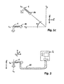
- the detection of the change in the tool position during the actual change in position of the tool 1 is carried out by determining at least one angular deviation (in the present case exactly one angular deviation) ⁇ of the newly determined position vector in comparison to the temporally preceding position vector.
- Fig. 1c symbolically shows this step of determining the at least one angular deviation ⁇ .
- the longitudinal axis L 2 which extends in the longitudinal direction of the handle of the tool 1, for comparison with a direction perpendicular to the gravitational acceleration G adjusted.
- the adjustment allows the determination of at least one first position vector, which is not shown here, but extends in the x-direction.
- an angular deviation ⁇ between the first and second position vector can be determined.
- This angular deviation ⁇ allows the provision of suitable information about the orientation of the tool, so that a tool control after receiving this information can set a suitable operating mode of the tool 1.
- the choice of the operating mode depends on the work task.
- the angular deviation ⁇ can be determined by initially the tool position with the direction or position of the vector of gravitational acceleration G is adjusted. Accordingly, a comparison with the in Fig. 1a represented axis L 1 along the tool head of the tool 1 done.
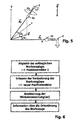
- Fig. 2 shows a further embodiment of the tool 1 according to the invention with tool control 2, which differs from the in the Fig. 1a and 1b shown embodiments only differs in that the sensor 10 is connected to the tool control 2 is not wireless but via a fixed conductor 11. Of the Fixed conductor 11 may in this case be included in a cable package together with other supply and discharge lines between the tool 1 and the tool control 2. Again, it is possible that the transmission of the sensor data from the sensor 10 to the tool control is not direct, but via a detection unit, which is not shown here, and which is the tool control 2 upstream.
- Fig. 3 is a schematic representation of an embodiment of the method according to the invention again stating the explicit position vectors for determining an angular deviation in space shown.
- the tool 1 is first made of a layer which by the A 1 position vector is described, transferred to a second position, which by the position vector A 2 is described.
- the change in position can be done freely in the room here.
- the value of the angular deviation ⁇ is determined, which is provided for determining information about the orientation of the tool 1.
- the position vector A In this case, 1 may be the first position vector of the tool 1, which is determined, for example, when aligning the initial tool position with a reference position, or also a position vector subsequent thereto in time.
- the position vector A 1 with respect to the direction of gravitational acceleration G certainly.
- the tool 1 is in a fixed position with respect to the direction of the gravitational acceleration vector G bring so that both are in a fixed relationship to each other.
- the position vector A 1 parallel to the vector of the gravitational field G runs.
- a further embodiment of the method according to the invention for determining the change in position of a hand-held tool is shown in space.
- the tool 1 in turn is made of an initial position, which by the position vector A 1 , in a temporally subsequent position, which by the position vector A 2 , transferred.
- An angle deviation ⁇ is determined between the two position vectors.
- information about the orientation of the tool is determined from the determined angular deviation ⁇ , which allows to distinguish whether the tool is arranged in a region 1 or in a region 2.
- Both areas are assigned to an operating mode of the tool 1, so that when the tool position is exceeded from area 1 to area 2 a change in the operating mode takes place.
- both areas 1 and 2 only by an angular position of the tool 1 in space are distinguished from each other.
- both areas are not areas of a coordinate system whose description would require the detection of three spatial directions.
- the region 1 is shown as a truncated cone whose tip coincides with the origin of the coordinate system. Consequently, the tool in any spatial direction by the angle ⁇ of his by the A Moving position 1 shown initial position vector, it can be determined by means of the calculated angular deviation ⁇ , whether the tool 1 has been transferred from the area 1 in the area 2. When transfer has taken place, a change in the operating mode can be initiated by the tool control 2, not shown.
- Fig. 5 shows a further embodiment of the inventive method for determining a change in position of a hand-held tool, which determines a total of three angular deviations ⁇ 1 , ⁇ 2 and ⁇ 3 to determine a precise position or exact orientation of the tool 1 in space.
- the angular deviation ⁇ 1 corresponds to an azimuth angle.
- the angle deviation ⁇ 2 corresponds to a polar angle. Both can be made from suitable trigonometric ratios of the position vector A 1 and the temporally subsequent position vector A 2 are determined.
- the angular deviation ⁇ 1 hereby indicates the angular deviation of the vector P projected into the x, z plane, which results from the projection of the position vector A 2 in the x, z plane is determined.
- a further angular deviation ⁇ 3 is determined, which detects a rotation about the longitudinal extension direction of the handle of the tool 1.
- the use of two or more angles may be meaningful both for initialization to equalize the initial tool location to a reference position and for determining the time-sequential orientation of the tool.
- the initialization can be done via multiple position vectors in order to be able to more fully describe the position of the tool in space.
- additional orientation information about whether and in which angle the tool is arranged in a position left or right of a workpiece.
- Fig. 6 shows a flowchart illustrating an embodiment of the inventive method for determining a change in position of a hand-held tool.
- the adjustment of the initial tool position for determining a position vector 1 is required first.
- the tool is suitably changed in its spatial position by the worker in the work process, wherein the detection of the change in the tool position can be done by a temporally subsequent new position vector.
- the angular deviation of position vector and the newly determined position vector allows conclusions about how the tool 1 has changed with respect to the reference position.
- the angular deviation or the angular deviations is provided as information about the orientation of the tool.
- the angular deviation or the angular deviations can also be correspondingly processed in an alternative embodiment, so that they contribute to the determination of the information about the orientation of the tool.
Landscapes
- Engineering & Computer Science (AREA)
- Mechanical Engineering (AREA)
- Physics & Mathematics (AREA)
- Optics & Photonics (AREA)
- General Physics & Mathematics (AREA)
- Numerical Control (AREA)
- Manipulator (AREA)
- Drilling And Boring (AREA)
- Portable Power Tools In General (AREA)
Applications Claiming Priority (1)
| Application Number | Priority Date | Filing Date | Title |
|---|---|---|---|
| DE102011053798A DE102011053798A1 (de) | 2011-09-20 | 2011-09-20 | Verfahren zur Bestimmung einer Lageänderung eines Werkzeuges sowie das Werkzeug und die Werkzeugsteuerung |
Publications (2)
| Publication Number | Publication Date |
|---|---|
| EP2581165A2 true EP2581165A2 (fr) | 2013-04-17 |
| EP2581165A3 EP2581165A3 (fr) | 2018-04-04 |
Family
ID=46758655
Family Applications (1)
| Application Number | Title | Priority Date | Filing Date |
|---|---|---|---|
| EP12182897.4A Withdrawn EP2581165A3 (fr) | 2011-09-20 | 2012-09-04 | Procédé de détermination d'un changement de position d'un outil ainsi que l'outil et la commande de l'outil |
Country Status (6)
| Country | Link |
|---|---|
| US (1) | US20130081293A1 (fr) |
| EP (1) | EP2581165A3 (fr) |
| JP (1) | JP2013066999A (fr) |
| KR (1) | KR20130031225A (fr) |
| CN (1) | CN103009353A (fr) |
| DE (1) | DE102011053798A1 (fr) |
Cited By (2)
| Publication number | Priority date | Publication date | Assignee | Title |
|---|---|---|---|---|
| EP3072637A3 (fr) * | 2015-03-10 | 2016-12-21 | Robert Bosch Gmbh | Outil et procédé de traitement d'une pièce avec un outil |
| EP3138651A1 (fr) * | 2015-08-12 | 2017-03-08 | Illinois Tool Works Inc. | Système de support d'électrode de soudage de bâtonnet |
Families Citing this family (76)
| Publication number | Priority date | Publication date | Assignee | Title |
|---|---|---|---|---|
| US9352411B2 (en) | 2008-05-28 | 2016-05-31 | Illinois Tool Works Inc. | Welding training system |
| US9993891B2 (en) | 2010-07-14 | 2018-06-12 | Illinois Tool Works Inc. | Welding parameter control via welder motion or position monitoring |
| US9101994B2 (en) | 2011-08-10 | 2015-08-11 | Illinois Tool Works Inc. | System and device for welding training |
| US9573215B2 (en) | 2012-02-10 | 2017-02-21 | Illinois Tool Works Inc. | Sound-based weld travel speed sensing system and method |
| CA2780077A1 (fr) * | 2012-03-22 | 2013-09-22 | Antonio Trindade | Dispositif et systeme de nivellement et de profilage |
| US9583014B2 (en) | 2012-11-09 | 2017-02-28 | Illinois Tool Works Inc. | System and device for welding training |
| US9368045B2 (en) | 2012-11-09 | 2016-06-14 | Illinois Tool Works Inc. | System and device for welding training |
| US9666100B2 (en) | 2013-03-15 | 2017-05-30 | Illinois Tool Works Inc. | Calibration devices for a welding training system |
| US9583023B2 (en) | 2013-03-15 | 2017-02-28 | Illinois Tool Works Inc. | Welding torch for a welding training system |
| US9672757B2 (en) | 2013-03-15 | 2017-06-06 | Illinois Tool Works Inc. | Multi-mode software and method for a welding training system |
| US9728103B2 (en) | 2013-03-15 | 2017-08-08 | Illinois Tool Works Inc. | Data storage and analysis for a welding training system |
| US9713852B2 (en) | 2013-03-15 | 2017-07-25 | Illinois Tool Works Inc. | Welding training systems and devices |
| US11090753B2 (en) | 2013-06-21 | 2021-08-17 | Illinois Tool Works Inc. | System and method for determining weld travel speed |
| US10056010B2 (en) | 2013-12-03 | 2018-08-21 | Illinois Tool Works Inc. | Systems and methods for a weld training system |
| US9589481B2 (en) | 2014-01-07 | 2017-03-07 | Illinois Tool Works Inc. | Welding software for detection and control of devices and for analysis of data |
| US10170019B2 (en) | 2014-01-07 | 2019-01-01 | Illinois Tool Works Inc. | Feedback from a welding torch of a welding system |
| US10105782B2 (en) | 2014-01-07 | 2018-10-23 | Illinois Tool Works Inc. | Feedback from a welding torch of a welding system |
| US9724788B2 (en) | 2014-01-07 | 2017-08-08 | Illinois Tool Works Inc. | Electrical assemblies for a welding system |
| US9751149B2 (en) | 2014-01-07 | 2017-09-05 | Illinois Tool Works Inc. | Welding stand for a welding system |
| US9757819B2 (en) | 2014-01-07 | 2017-09-12 | Illinois Tool Works Inc. | Calibration tool and method for a welding system |
| US10335883B2 (en) * | 2014-06-05 | 2019-07-02 | Illinois Tool Works Inc. | Gravity-based weld travel speed sensing system and method |
| US9937578B2 (en) | 2014-06-27 | 2018-04-10 | Illinois Tool Works Inc. | System and method for remote welding training |
| US10665128B2 (en) | 2014-06-27 | 2020-05-26 | Illinois Tool Works Inc. | System and method of monitoring welding information |
| US10307853B2 (en) | 2014-06-27 | 2019-06-04 | Illinois Tool Works Inc. | System and method for managing welding data |
| US9862049B2 (en) | 2014-06-27 | 2018-01-09 | Illinois Tool Works Inc. | System and method of welding system operator identification |
| US9724787B2 (en) | 2014-08-07 | 2017-08-08 | Illinois Tool Works Inc. | System and method of monitoring a welding environment |
| US11014183B2 (en) | 2014-08-07 | 2021-05-25 | Illinois Tool Works Inc. | System and method of marking a welding workpiece |
| US9875665B2 (en) | 2014-08-18 | 2018-01-23 | Illinois Tool Works Inc. | Weld training system and method |
| US10987762B2 (en) | 2014-09-30 | 2021-04-27 | Illinois Tool Works Inc. | Armband based systems and methods for controlling welding equipment using gestures and like motions |
| US10201868B2 (en) | 2014-09-30 | 2019-02-12 | Illinois Tool Works Inc. | Systems and methods for gesture control of a welding system |
| US10239147B2 (en) | 2014-10-16 | 2019-03-26 | Illinois Tool Works Inc. | Sensor-based power controls for a welding system |
| US11247289B2 (en) | 2014-10-16 | 2022-02-15 | Illinois Tool Works Inc. | Remote power supply parameter adjustment |
| US10210773B2 (en) | 2014-11-05 | 2019-02-19 | Illinois Tool Works Inc. | System and method for welding torch display |
| US10373304B2 (en) | 2014-11-05 | 2019-08-06 | Illinois Tool Works Inc. | System and method of arranging welding device markers |
| US10417934B2 (en) | 2014-11-05 | 2019-09-17 | Illinois Tool Works Inc. | System and method of reviewing weld data |
| US10204406B2 (en) | 2014-11-05 | 2019-02-12 | Illinois Tool Works Inc. | System and method of controlling welding system camera exposure and marker illumination |
| US10490098B2 (en) | 2014-11-05 | 2019-11-26 | Illinois Tool Works Inc. | System and method of recording multi-run data |
| US10402959B2 (en) | 2014-11-05 | 2019-09-03 | Illinois Tool Works Inc. | System and method of active torch marker control |
| US10076802B2 (en) * | 2014-12-19 | 2018-09-18 | Illinois Tool Works Inc. | Electric arc start systems and methods |
| US9975196B2 (en) | 2015-01-05 | 2018-05-22 | University Of Kentucky Research Foundation | Measurement of three-dimensional welding torch orientation for manual arc welding process |
| US10773329B2 (en) | 2015-01-20 | 2020-09-15 | Illinois Tool Works Inc. | Multiple input welding vision system |
| EP3061544B1 (fr) * | 2015-02-24 | 2018-07-04 | GESIPA Blindniettechnik GmbH | Dispositif de pose de fixation aveugle |
| US10406638B2 (en) | 2015-02-27 | 2019-09-10 | Illinois Tool Works Inc. | Augmented vision system with active welder guidance |
| US10448692B2 (en) | 2015-03-06 | 2019-10-22 | Illinois Tool Works Inc. | Sensor assisted head mounted displays for welding |
| CN107980153B (zh) | 2015-03-09 | 2021-10-22 | 伊利诺斯工具制品有限公司 | 提供与焊接操作相关联的视觉信息的方法和装置 |
| US9666160B2 (en) | 2015-03-26 | 2017-05-30 | Illinois Tool Works Inc. | Control of mediated reality welding system based on lighting conditions |
| US9977242B2 (en) | 2015-03-26 | 2018-05-22 | Illinois Tool Works Inc. | Control of mediated reality welding system based on lighting conditions |
| US10427239B2 (en) | 2015-04-02 | 2019-10-01 | Illinois Tool Works Inc. | Systems and methods for tracking weld training arc parameters |
| US10363632B2 (en) | 2015-06-24 | 2019-07-30 | Illinois Tool Works Inc. | Time of flight camera for welding machine vision |
| US10438505B2 (en) | 2015-08-12 | 2019-10-08 | Illinois Tool Works | Welding training system interface |
| US10657839B2 (en) | 2015-08-12 | 2020-05-19 | Illinois Tool Works Inc. | Stick welding electrode holders with real-time feedback features |
| US10373517B2 (en) | 2015-08-12 | 2019-08-06 | Illinois Tool Works Inc. | Simulation stick welding electrode holder systems and methods |
| JP6709129B2 (ja) | 2016-08-05 | 2020-06-10 | 株式会社マキタ | 電動工具 |
| EP3292929B2 (fr) * | 2016-09-09 | 2025-07-02 | Sandvik Intellectual Property AB | Estimation d'orientation d'un outil de coupe |
| DE102017211003A1 (de) * | 2017-06-29 | 2019-01-03 | Robert Bosch Gmbh | Verfahren zur Steuerung eines Motors einer Handwerkzeugmaschine |
| DE102017216697A1 (de) | 2017-09-21 | 2019-03-21 | Robert Bosch Gmbh | Werkzeugmaschinenvorrichtung zu einer Steuerung und/oder Regelung zumindest einer Werkzeugmaschinenfunktion einer Werkzeugmaschine |
| DE102018210127A1 (de) * | 2018-06-21 | 2019-12-24 | Robert Bosch Gmbh | Verfahren zum Anziehen einer Schraubverbindung |
| US11484381B2 (en) * | 2018-06-21 | 2022-11-01 | Ruthless, LLC | Instrument alignment feedback system and method |
| CN109332763B (zh) * | 2018-10-09 | 2020-12-04 | 江西科技学院 | 断电保护方法、系统、可读存储介质及电锤钻 |
| US11521512B2 (en) | 2019-02-19 | 2022-12-06 | Illinois Tool Works Inc. | Systems for simulating joining operations using mobile devices |
| US11450233B2 (en) | 2019-02-19 | 2022-09-20 | Illinois Tool Works Inc. | Systems for simulating joining operations using mobile devices |
| US11776423B2 (en) | 2019-07-22 | 2023-10-03 | Illinois Tool Works Inc. | Connection boxes for gas tungsten arc welding training systems |
| US11288978B2 (en) | 2019-07-22 | 2022-03-29 | Illinois Tool Works Inc. | Gas tungsten arc welding training systems |
| WO2021072061A1 (fr) | 2019-10-08 | 2021-04-15 | Spindle Karlton E | Poignée d'instrument destinée à être utilisée avec un système et un procédé de rétroaction d'alignement d'instrument |
| US12198568B2 (en) | 2019-11-25 | 2025-01-14 | Illinois Tool Works Inc. | Weld training simulations using mobile devices, modular workpieces, and simulated welding equipment |
| CN110930834B (zh) * | 2019-11-25 | 2021-10-12 | 齐齐哈尔大学 | 一种获得匀加速运动液体液面高差的实验装置和方法 |
| US11322037B2 (en) | 2019-11-25 | 2022-05-03 | Illinois Tool Works Inc. | Weld training simulations using mobile devices, modular workpieces, and simulated welding equipment |
| US11721231B2 (en) | 2019-11-25 | 2023-08-08 | Illinois Tool Works Inc. | Weld training simulations using mobile devices, modular workpieces, and simulated welding equipment |
| DE102020205666B4 (de) | 2020-05-05 | 2023-11-02 | Fronius International Gmbh | Vorrichtung zur Erfassung einer Lage eines handgeführten Schweißbrenners |
| US12279993B2 (en) | 2020-07-31 | 2025-04-22 | Illinois Tool Works Inc. | Smart welding helmet modules with adaptable helmet devices |
| DE102020127509A1 (de) * | 2020-10-19 | 2022-04-21 | Haimer Gmbh | Werkzeughalter mit Messvorrichtung |
| US12433792B2 (en) | 2020-12-14 | 2025-10-07 | Illinois Tool Works Inc. | Smart welding helmets with arc time tracking verification and lens maintenance detection |
| JP7687016B2 (ja) * | 2021-03-25 | 2025-06-03 | セイコーエプソン株式会社 | 立体物印刷方法 |
| KR102733323B1 (ko) * | 2022-08-25 | 2024-11-21 | 한국로봇융합연구원 | 고소도장 로봇 |
| KR102775878B1 (ko) * | 2022-08-30 | 2025-03-05 | 한국로봇융합연구원 | 고소도장 로봇 통합제어 시스템 |
| JP2024070364A (ja) * | 2022-11-11 | 2024-05-23 | Swcc株式会社 | 教育システム |
Citations (1)
| Publication number | Priority date | Publication date | Assignee | Title |
|---|---|---|---|---|
| EP1812200B1 (fr) | 2004-10-13 | 2009-05-13 | Erdogan Karakas | Dispositif pour la mise en oeuvre d'un procede de traitement de surface, d'assemblage ou de separation, en particulier d'un procede de soudage |
Family Cites Families (24)
| Publication number | Priority date | Publication date | Assignee | Title |
|---|---|---|---|---|
| US1292969A (en) * | 1917-07-03 | 1919-01-28 | Benjamin R Sturgis | Combination-plane. |
| US2806296A (en) * | 1956-07-13 | 1957-09-17 | Weichert Joseph | Level attachment for a portable electric drill |
| US3052036A (en) * | 1958-09-15 | 1962-09-04 | Raymond J Oliver | Bubble type level for hand drill |
| US4189726A (en) * | 1977-10-27 | 1980-02-19 | Miller Richard L | Automatic orientation circuit indicator device for portable power tools and the like |
| US4564322A (en) * | 1983-09-06 | 1986-01-14 | Stapley Keith D | Drill scope |
| US4546549A (en) * | 1984-07-05 | 1985-10-15 | Terry Duperon | Adjustable spirit level construction |
| US4986002A (en) * | 1990-01-09 | 1991-01-22 | Ford Motor Company | Quick setting angle device for a welding torch |
| US6568021B1 (en) * | 2000-02-10 | 2003-05-27 | George W. Wood | Trowel with levels |
| AU2002250142A1 (en) * | 2001-02-22 | 2002-09-12 | Toolz, Ltd. | Detecting tool orientation alignment depth and leveling |
| US6810596B2 (en) * | 2001-07-26 | 2004-11-02 | Black & Decker Inc. | Drill level indicator |
| DE10303005A1 (de) * | 2003-01-27 | 2004-08-05 | Hilti Ag | Betriebsdatenerfassungseinheit für Elektrohandwerkzeugmaschinen |
| CA2472421C (fr) * | 2004-06-25 | 2012-04-24 | Measurand Instruments Inc. | Dispositif et methode de mesure de la forme et de l'acceleration |
| EP1792039A4 (fr) * | 2004-08-11 | 2010-09-15 | William Szieff | Outil dote d'indicateurs de mouvement et d'orientation |
| US7650699B2 (en) * | 2005-07-22 | 2010-01-26 | Kazuhiro Yamamoto | Electric drill |
| US7506453B2 (en) * | 2006-06-19 | 2009-03-24 | International Business Machines Corporation | Method and apparatus for orienting a hand tool |
| DE102006034270A1 (de) * | 2006-07-18 | 2008-01-24 | C. & E. Fein Gmbh | Ortungssystem zur Ortung der Position eines Werkzeugs |
| JP2010058217A (ja) * | 2008-09-03 | 2010-03-18 | Toyota Auto Body Co Ltd | ネジの焼付き防止装置 |
| JP2010094757A (ja) * | 2008-10-15 | 2010-04-30 | Sakamoto Electric Mfg Co Ltd | 動力工具 |
| DE102008043791A1 (de) * | 2008-11-17 | 2010-05-20 | Robert Bosch Gmbh | Handwerkzeugmaschinenvorrichtung |
| DE102008054455A1 (de) * | 2008-12-10 | 2010-06-17 | Robert Bosch Gmbh | Orientierungssensor, Orientierungsregler, Vorrichtung sowie System |
| US8274013B2 (en) * | 2009-03-09 | 2012-09-25 | Lincoln Global, Inc. | System for tracking and analyzing welding activity |
| JP5344243B2 (ja) * | 2009-09-24 | 2013-11-20 | 富士通株式会社 | 電動ドライバの姿勢監視装置、および姿勢監視装置付き電動ドライバ |
| DE102009046789A1 (de) * | 2009-11-17 | 2011-05-19 | Robert Bosch Gmbh | Handwerkzeugmaschinenvorrichtung |
| JP5252589B2 (ja) * | 2010-03-17 | 2013-07-31 | Necインフロンティア株式会社 | 傾き検出機能付き電動ドライバ及び電動ドライバによるネジ締め付け方法 |
-
2011
- 2011-09-20 DE DE102011053798A patent/DE102011053798A1/de not_active Ceased
-
2012
- 2012-09-04 EP EP12182897.4A patent/EP2581165A3/fr not_active Withdrawn
- 2012-09-18 US US13/621,937 patent/US20130081293A1/en not_active Abandoned
- 2012-09-19 JP JP2012205507A patent/JP2013066999A/ja active Pending
- 2012-09-20 CN CN2012103537546A patent/CN103009353A/zh active Pending
- 2012-09-20 KR KR1020120104490A patent/KR20130031225A/ko not_active Ceased
Patent Citations (1)
| Publication number | Priority date | Publication date | Assignee | Title |
|---|---|---|---|---|
| EP1812200B1 (fr) | 2004-10-13 | 2009-05-13 | Erdogan Karakas | Dispositif pour la mise en oeuvre d'un procede de traitement de surface, d'assemblage ou de separation, en particulier d'un procede de soudage |
Cited By (2)
| Publication number | Priority date | Publication date | Assignee | Title |
|---|---|---|---|---|
| EP3072637A3 (fr) * | 2015-03-10 | 2016-12-21 | Robert Bosch Gmbh | Outil et procédé de traitement d'une pièce avec un outil |
| EP3138651A1 (fr) * | 2015-08-12 | 2017-03-08 | Illinois Tool Works Inc. | Système de support d'électrode de soudage de bâtonnet |
Also Published As
| Publication number | Publication date |
|---|---|
| KR20130031225A (ko) | 2013-03-28 |
| DE102011053798A1 (de) | 2013-03-21 |
| US20130081293A1 (en) | 2013-04-04 |
| JP2013066999A (ja) | 2013-04-18 |
| CN103009353A (zh) | 2013-04-03 |
| EP2581165A3 (fr) | 2018-04-04 |
Similar Documents
| Publication | Publication Date | Title |
|---|---|---|
| EP2581165A2 (fr) | Procédé de détermination d'un changement de position d'un outil ainsi que l'outil et la commande de l'outil | |
| DE102014108956B4 (de) | Vorrichtung zum Entgraten mit visuellem Sensor und Kraftsensor | |
| DE102012104194B4 (de) | Roboter und Punktschweissroboter mit lernender Steuerungsfunktion | |
| EP1812200B2 (fr) | Dispositif pour la mise en oeuvre d'un procede de traitement de surface, d'assemblage ou de separation, en particulier d'un procede de soudage | |
| AT398050B (de) | Schweissroboter | |
| EP2000872B1 (fr) | Robot industriel et procédé de programmation d'un robot industriel | |
| DE202007011584U1 (de) | Schweißgerät | |
| EP2566667B1 (fr) | Appareil à main et procédé de commande et/ou de programmation d'un manipulateur | |
| DE102019125335B4 (de) | Robotersteuervorrichtung zur Steuerung der Kreisbogenbewegung eines Roboters | |
| DE102020100803A1 (de) | Folgeroboter und Roboterarbeitssystem | |
| EP3147086A1 (fr) | Automatisation d'operations de robot | |
| DE102011053799A1 (de) | Verfahren zur Steuerung von wenigstens einer Steuergröße eines Werkzeugs sowie das Werkzeug | |
| DE112021001173B4 (de) | Entgratungsvorrichtung und Steuerungssystem | |
| DE3439096C2 (fr) | ||
| DE102014226933B3 (de) | Vorrichtung und Verfahren zum Aufnehmen von Positionen | |
| WO2016078760A1 (fr) | Procédé et système de correction d'une trajectoire d'usinage d'un outil guidé par un robot | |
| EP2012208A2 (fr) | Outil manuel de programmation | |
| DE102015007829B4 (de) | Rechnerunabhängige Lehrvorrichtung mit Simulationsverwendung | |
| DE102020125631A1 (de) | Robotersystem mit einem roboter, der einen betätigungsabschnitt aufweist, und verfahren zum steuern eines roboters | |
| DE102020119550B4 (de) | Vorrichtung, Robotersteuereinrichtung, Robotersystem und Verfahren zum Einstellen eines Roboterkoordinatensystems | |
| DE102016214307A1 (de) | Einspannvorrichtung für ein Werkstück | |
| WO2010075906A1 (fr) | Procédé et dispositif de sélection d'une position mémorisée d'un point de travail d'un manipulateur | |
| EP1485225B1 (fr) | Procede et dispositif de soudage pour soudage de contour | |
| EP3117280A2 (fr) | Procédé pour faire fonctionner un robot et robot correspondant équipé d'un dispositif palpeur mécanique | |
| EP3676039B1 (fr) | Procédé et dispositif de fourniture d'un signal à distance référencé permettant la commande de positionnement d'un chalumeau soudeur |
Legal Events
| Date | Code | Title | Description |
|---|---|---|---|
| PUAI | Public reference made under article 153(3) epc to a published international application that has entered the european phase |
Free format text: ORIGINAL CODE: 0009012 |
|
| AK | Designated contracting states |
Kind code of ref document: A2 Designated state(s): AL AT BE BG CH CY CZ DE DK EE ES FI FR GB GR HR HU IE IS IT LI LT LU LV MC MK MT NL NO PL PT RO RS SE SI SK SM TR |
|
| AX | Request for extension of the european patent |
Extension state: BA ME |
|
| RAP1 | Party data changed (applicant data changed or rights of an application transferred) |
Owner name: ILHUNG MANUFACTURING CO., LTD. |
|
| PUAL | Search report despatched |
Free format text: ORIGINAL CODE: 0009013 |
|
| AK | Designated contracting states |
Kind code of ref document: A3 Designated state(s): AL AT BE BG CH CY CZ DE DK EE ES FI FR GB GR HR HU IE IS IT LI LT LU LV MC MK MT NL NO PL PT RO RS SE SI SK SM TR |
|
| AX | Request for extension of the european patent |
Extension state: BA ME |
|
| RIC1 | Information provided on ipc code assigned before grant |
Ipc: B25F 5/00 20060101ALI20180226BHEP Ipc: B23K 37/02 20060101AFI20180226BHEP |
|
| STAA | Information on the status of an ep patent application or granted ep patent |
Free format text: STATUS: THE APPLICATION IS DEEMED TO BE WITHDRAWN |
|
| 18D | Application deemed to be withdrawn |
Effective date: 20181005 |