EP2581255A1 - Entraînement de véhicule doté d'un moteur à combustion interne, boîte de transfert, véhicule roulant sur rails ou ne roulant pas sur rails, et procédé de fonctionnement d'un véhicule comportant un moteur à combustion interne - Google Patents
Entraînement de véhicule doté d'un moteur à combustion interne, boîte de transfert, véhicule roulant sur rails ou ne roulant pas sur rails, et procédé de fonctionnement d'un véhicule comportant un moteur à combustion interne Download PDFInfo
- Publication number
- EP2581255A1 EP2581255A1 EP11008185.8A EP11008185A EP2581255A1 EP 2581255 A1 EP2581255 A1 EP 2581255A1 EP 11008185 A EP11008185 A EP 11008185A EP 2581255 A1 EP2581255 A1 EP 2581255A1
- Authority
- EP
- European Patent Office
- Prior art keywords
- drive
- vehicle
- transfer case
- shaft
- output
- Prior art date
- Legal status (The legal status is an assumption and is not a legal conclusion. Google has not performed a legal analysis and makes no representation as to the accuracy of the status listed.)
- Granted
Links
Images


Classifications
-
- B—PERFORMING OPERATIONS; TRANSPORTING
- B60—VEHICLES IN GENERAL
- B60K—ARRANGEMENT OR MOUNTING OF PROPULSION UNITS OR OF TRANSMISSIONS IN VEHICLES; ARRANGEMENT OR MOUNTING OF PLURAL DIVERSE PRIME-MOVERS IN VEHICLES; AUXILIARY DRIVES FOR VEHICLES; INSTRUMENTATION OR DASHBOARDS FOR VEHICLES; ARRANGEMENTS IN CONNECTION WITH COOLING, AIR INTAKE, GAS EXHAUST OR FUEL SUPPLY OF PROPULSION UNITS IN VEHICLES
- B60K17/00—Arrangement or mounting of transmissions in vehicles
- B60K17/34—Arrangement or mounting of transmissions in vehicles for driving both front and rear wheels, e.g. four wheel drive vehicles
- B60K17/344—Arrangement or mounting of transmissions in vehicles for driving both front and rear wheels, e.g. four wheel drive vehicles having a transfer gear
-
- B—PERFORMING OPERATIONS; TRANSPORTING
- B60—VEHICLES IN GENERAL
- B60K—ARRANGEMENT OR MOUNTING OF PROPULSION UNITS OR OF TRANSMISSIONS IN VEHICLES; ARRANGEMENT OR MOUNTING OF PLURAL DIVERSE PRIME-MOVERS IN VEHICLES; AUXILIARY DRIVES FOR VEHICLES; INSTRUMENTATION OR DASHBOARDS FOR VEHICLES; ARRANGEMENTS IN CONNECTION WITH COOLING, AIR INTAKE, GAS EXHAUST OR FUEL SUPPLY OF PROPULSION UNITS IN VEHICLES
- B60K17/00—Arrangement or mounting of transmissions in vehicles
- B60K17/04—Arrangement or mounting of transmissions in vehicles characterised by arrangement, location or kind of gearing
- B60K17/10—Arrangement or mounting of transmissions in vehicles characterised by arrangement, location or kind of gearing of fluid gearing
-
- B—PERFORMING OPERATIONS; TRANSPORTING
- B60—VEHICLES IN GENERAL
- B60Y—INDEXING SCHEME RELATING TO ASPECTS CROSS-CUTTING VEHICLE TECHNOLOGY
- B60Y2200/00—Type of vehicle
- B60Y2200/10—Road Vehicles
- B60Y2200/14—Trucks; Load vehicles, Busses
Definitions
- the invention relates on the one hand to a vehicle drive with an internal combustion engine for providing a drive power, with a drive train for transmitting the drive power to a plurality of output devices, with a drive gear for selecting drive ratios and with at least one transfer case for distributing the drive power to the output devices, wherein the at least one Transfer case is arranged drivable by means of an output shaft member of the vehicle transmission in the drive train.
- the invention relates to a transfer case with a drive shaft input for driving the transfer case by means of a drive device of a vehicle drive and with at least one drive shaft output for driving at least one output device.
- the invention also relates to a rail vehicle with a vehicle drive or a rail-bound vehicle with a vehicle drive.
- the invention relates to a method for operating a vehicle having an internal combustion engine, in which a drive power provided by the internal combustion engine is distributed by means of a transfer case to various output devices and wherein both the vehicle itself and a work implement associated with the vehicle are driven by the internal combustion engine can.
- Generic vehicle drives are well known from the prior art and are used especially in trucks or commercial vehicles, wherein the available drive power can be distributed to different output devices by means of at least one transfer case.
- this transfer case is used in addition to the actual driving gear of the motor vehicle for a so-called crawl of the motor vehicle, which is mainly intended that the vehicle can be moved as slowly forward or less often backwards.
- this may be the case when a working device is moved by means of the motor vehicle, in which the slowest possible locomotion is required.
- a vehicle drive with an internal combustion engine for providing drive power, with a drive train for transmitting the drive power to a plurality of output devices, with a drive gear for selecting drive ratios and with at least one transfer case for distributing the drive power to the output devices in which the at least one transfer case is drivably disposed in the drive train by means of an output shaft element of the drive transmission, wherein the vehicle drive for cumulative or alternative driving of the at least one transfer case comprises a further drive device.
- the transfer case can be driven cumulatively or alternatively at least partially by means of the further drive device, so that at least one input-side input shaft or preferably at least two output-side output shaft of the transfer case can be driven with a particularly low rotational speed, but nevertheless with high torque.
- vehicle drive in the context of the invention essentially describes a drive train of a motor vehicle comprising an internal combustion engine. Instead of the internal combustion engine Optionally, an electric motor could also be used as drive device or main drive motor.
- the further drive device is only a secondary drive motor with respect to the vehicle drive, by means of which the transfer case can be driven at least partially.
- drive train in the sense of the invention, in turn, includes required components, such as shaft elements, for transmitting a drive power provided by the internal combustion engine to the respective output device.
- the main gearbox for selecting a gear of the motor vehicle.
- the drive gear is designed as a manual transmission.
- the present drive transmission differs from other auxiliary transmissions of the vehicle drive, such as the transfer case always present here, the transfer case presently on the one hand at least two input shafts and on the other hand preferably at least two output shafts and it also provided on one of the two input shafts drive power to the can distribute at least two output shafts.
- the object of the invention is also achieved by a transfer case with a drive shaft input for driving the transfer case by means of a drive device of a vehicle drive and at least one drive shaft output for driving at least one output device, wherein the transfer case has at least one further drive shaft input for a further drive device, and wherein the twomaschinewelleneinlandais are switchable.
- the further drive shaft input is an intermediate shaft of the transfer case, which was previously not used within the meaning of the invention as an input shaft for realizing a creep drive.
- this intermediate shaft constructionally particularly easy as an input shaft for a Kriechfahrtantrieb, it is drilled and in the bore a shaft piece is shrunk, so that a particularly high-torque power transmission is structurally simple available.
- switchable in the sense of the present invention describes the function that the transfer case can be driven either via the first or the second drive shaft input.
- the transfer case is either driven directly via an output shaft element of the drive gear or by means of the further drive device.
- switchability of the two drive shaft inputs can also be achieved by means of further coupling devices which are arranged to act between the drive gear and the transfer case or the further drive device and / or the further drive device and the transfer case.
- an advantageous safety device is integrated in the vehicle drive in order to avoid critical drive situations, in particular at the transfer case, for example, that both drive shaft inputs are actively addressed and activated.
- first transfer case shaft could be driven via the first drive shaft input and second transfer shaft via the secondmaschinewelleneingang at appropriately designed transfer cases.
- the further drive device is a hydraulic drive device, since such a design can be easily integrated into conventional motor vehicles.
- the hydraulic drive device is advantageously a continuously variable drive possible, which can be controlled stepless down to a standstill.
- the object of the invention is also achieved by a rail vehicle with a vehicle drive or a rail vehicle with a vehicle drive, in which the vehicles have a vehicle drive and / or a transfer case according to at least one of the features mentioned here.
- the term "rail-bound vehicle” essentially designates road vehicles, such as, for example, lorries or commercial vehicles.
- a rail-bound vehicle can strike any direction of travel. These can be used not only on roads but also on unpaved roads or terrain.
- the object of the invention is also particularly advantageously solved by the vehicle drive comprises a further drive device having Kriechfahrtantrieb.
- a further drive device having Kriechfahrtantrieb As already described, by means of an especially hydraulically operated alternative drive device, an extremely slow creeping motion can be provided on a vehicle, which, however, can guarantee a very high-torque drive power.
- the hydraulic drive device can be easily retrofitted to existing vehicle drives.
- a preferred embodiment of the present invention provides that the at least one transfer case has both a first drive shaft input for the drive gear and a second drive shaft input for the further drive device.
- the twomaschinewelleneinlandais are switchable, so preferably always only one drive means can drive the transfer case.
- Each of the drive shaft inputs has its own input shaft.
- the object of the invention is also achieved by a method for operating a vehicle having an internal combustion engine, in which a drive power provided by the internal combustion engine is distributed by means of a transfer case to various output devices and in which by means of the internal combustion engine, both the vehicle and a vehicle associated Implement can be driven, wherein the method is characterized in that an input shaft of a first drive shaft input of the transfer case by means of an output shaft member of a transfer case and an input shaft of a further drive shaft input of the transfer case by means of an output shaft member of another drive device are driven.
- a transfer case of a vehicle can be operated more varied and thus also more advantageously.
- one of the two drive shaft inputs of the transfer case can also be arranged advantageously opposite to different sides of the transfer case.
- the further drive device comprises at least one hydraulic motor and / or at least one hydraulic pump.
- a hydraulic pump is in this case driven directly by an output shaft of the drive gear.
- the hydraulic pump can in this case via a corresponding hydraulic line driving a distributor gear side arranged hydraulic motor, which then ultimately drives one of the input shafts of the transfer case.
- hydraulic drive device can be equipped only with a hydraulic motor. If desired, however, the hydraulic drive device may also comprise more than two hydraulic motors.
- the vehicle drive has more than one transfer case, which are to be driven at least partially by means of a hydraulic drive device or by means of hydraulic motors thereof.
- the further drive device can be driven in a structurally particularly simple manner if the further drive device is drivably arranged in the drive train by means of the internal combustion engine.
- a preferred variant of the method provides that the further drive device is driven by the internal combustion engine.
- a planetary gear for reducing an engine speed is arranged between the further drive device and the at least one transfer case, the rotational speed of, for example, a relatively high-revving oil engine can be reduced very simply to a drive rotational speed which is advantageous for the transfer case.
- a drive device comprises a PTO shaft for driving a working device or the like.
- an output device comprises a propeller shaft.
- a particularly slow creeping is accomplished by means of the hydraulic drive device via the second input shaft or the intermediate shaft of the transfer case, while the operation of the PTO is ensured by full torque of the internal combustion engine via the first input shaft of the transfer case.
- only the distributor shaft must be adjusted such that the drive power of the internal combustion engine is switched directly to the output device with the PTO and the drive power of the hydraulic drive device is passed to the output devices with the cardan shafts of the traction drive.
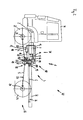
- vehicle drive 1 comprises an internal combustion engine 2 for providing a drive power, a drive train 3 for transmitting the drive power to a plurality of output devices 4, 5 and 6, a driving gear 7 for selecting drive ratios and a transfer case 8 for distributing the drive power to the output device 4, 5 and 6th
- the transfer case 8 is arranged drivable in the present drive train 3 by means of a drive output shaft element 9 of the drive transmission 7.
- a hydraulic drive device 10 which in particular by a hydraulic pump 11, a hydraulic motor 12 and a hydraulic line 13 connecting them comprises.
- the hydraulic pump 11 is arranged drivable in the drive train via a further drive output shaft element 14.
- the entire hydraulic drive device 10 via the drive gear 7 by means of the existing internal combustion engine 2 can be driven.
- the drive power provided by the hydraulic drive device 10 is transmitted to the transfer case 8 by means of a hydraulic motor output shaft member 15.
- Such switchability of the two drive shaft inputs 16 and 17, however, can also be achieved by means of further coupling devices 17A (here only explicitly numbered) acting between the drive gear 7 and the transfer case 8 or the hydraulic drive device 10 and / or the hydraulic drive device 10 and the transfer case 8 are arranged.
- a planetary gear 18 for additionally reducing a hydraulic motor speed is additionally arranged on the second drive shaft input 17.
- the two drive shaft inputs 16 and 17 are structurally advantageously arranged on a common drive shaft input side 19.
- an ideally standardized transfer case 8 can be used.
- the first output device 4 is a cardan shaft 20 for driving the front wheel axle 21 or the front wheels 22 (numbered here only by way of example).
- the second output device 5 is correspondingly a rear propeller shaft 23 for driving a rear wheel axle 24 or the rear wheels 25 (here only by way of example) numbered).
- the third output device 6 is a PTO shaft 26 for driving a working device, not shown here.
- an extremely slow travel of the truck 30 shown here can be made possible when the propulsion of the truck 30, as in the according to the illustration FIG. 2 shown further driving mode, by means of the hydraulic drive device 10 is accomplished.
- the present hydraulic drive device 10 represents an extremely effective creeper drive 31 of the vehicle drive 1 of the present truck 30 shown.
- the present transfer case 8 is a standard transfer case of conventional design, so that the modifications to the vehicle drive 1 are essentially limited only to the addition of the hydraulic drive device 10.
- Most transfer cases 8 conventional design usually have standard already on the second, but usually unused drive shaft input 17, so that the integration of the hydraulic drive device 10 in an existing vehicle drive 1 is structurally particularly simple.
- the present vehicle drive 1 is a very inexpensive to provide alternative to known vehicle drives, which are designed for a slow ride of a motor vehicle.
- the truck 30 also comprises a chassis 32 which, in addition to the vehicle drive 1, in particular still carries a chassis 33 on the one hand and a vehicle cabin 34 on the other hand.
- truck 130 is also equipped with a vehicle drive 101 according to the invention, which comprises a Kriechfahrtantrieb 131 based on a hydraulic drive device 110, so that the vehicle drive 101 is almost identical to the vehicle drive 1 from the embodiment of the FIGS. 1 and 2 is constructed.
- the vehicle drive 101 has an internal combustion engine 102, a drive train 103, first, second and third output devices 104, 105 and 106, as well as a drive gear 107 and a transfer case 108.
- the hydraulic drive device 110 is also characterized by a hydraulic pump 111 and a hydraulic motor 112 with a hydraulic motor output shaft element 115 and a hydraulic line 113 connecting them.
- the transfer case 108 differs from the transfer case 8 of the first embodiment in that a first drive shaft input 116 and a second drive shaft input 117 do not exist on a common drive shaft input side 19 (see FIGS. 1 and 2
- the first drive shaft input 116 is arranged on a drive shaft input front side 140 and the second drive shaft input 117 is arranged in the region of an inspection opening for an intermediate shaft on a drive shaft input rear side 141 of the transfer case 108.
- the drive gear 107 is characterized to drive the transfer case 108 again through a first drive output shaft member 109 and another drive output shaft member 114.
- a planetary gear 118 is provided to additionally reduce a hydraulic motor speed of the hydraulic motor 112 at the secondmaschinewelleneingang 117 accordingly, so that the transfer case 108 with respect to the first output device 104 and the second output device 105 can rotate extremely slowly , so that also an extremely slow crawl of the truck 130 is possible.
- the first output device 104 includes a front propeller shaft 120 for driving a front axle 121 and the front wheels 122 respectively.
- the second output device 105 comprises a rear propeller shaft 123 for driving a rear axle 124 and corresponding rear wheels 125.
- the third drive device 106 has a PTO shaft 126 for driving a working device not shown here, which can be driven by the truck 130.
- the output devices 104, 105 and 106 described above are connected downstream correspondingly assigned drive shaft outputs 127, 128 and 129 of the transfer case 108.
- the transfer case 208 can be driven in a previously known manner only via a driving gear 207 by means of an internal combustion engine 202.
- a first drive shaft input 216 is occupied at the transfer case 208.
- a second availablemaschinewelleneingang 217 is closed only by means of a cover 251 a revision opening and thus not in use.
- the vehicle drive 250 comprises a drive output shaft element 209, by means of which it is connected torque-fit with the transfer case 208.
- the transfer case 208 also has three drive shaft outputs 227, 228, and 229 for driving a front propeller shaft 220, a rear propeller shaft 223, and another output device 206 comprising a PTO shaft 226.
Landscapes
- Engineering & Computer Science (AREA)
- Chemical & Material Sciences (AREA)
- Combustion & Propulsion (AREA)
- Transportation (AREA)
- Mechanical Engineering (AREA)
- Arrangement And Driving Of Transmission Devices (AREA)
Priority Applications (1)
| Application Number | Priority Date | Filing Date | Title |
|---|---|---|---|
| EP20110008185 EP2581255B1 (fr) | 2011-10-10 | 2011-10-10 | Entraînement de véhicule doté d'un moteur à combustion interne, boîte de transfert, véhicule roulant sur rails ou ne roulant pas sur rails, et procédé de fonctionnement d'un véhicule comportant un moteur à combustion interne |
Applications Claiming Priority (1)
| Application Number | Priority Date | Filing Date | Title |
|---|---|---|---|
| EP20110008185 EP2581255B1 (fr) | 2011-10-10 | 2011-10-10 | Entraînement de véhicule doté d'un moteur à combustion interne, boîte de transfert, véhicule roulant sur rails ou ne roulant pas sur rails, et procédé de fonctionnement d'un véhicule comportant un moteur à combustion interne |
Publications (2)
| Publication Number | Publication Date |
|---|---|
| EP2581255A1 true EP2581255A1 (fr) | 2013-04-17 |
| EP2581255B1 EP2581255B1 (fr) | 2015-04-29 |
Family
ID=45715005
Family Applications (1)
| Application Number | Title | Priority Date | Filing Date |
|---|---|---|---|
| EP20110008185 Active EP2581255B1 (fr) | 2011-10-10 | 2011-10-10 | Entraînement de véhicule doté d'un moteur à combustion interne, boîte de transfert, véhicule roulant sur rails ou ne roulant pas sur rails, et procédé de fonctionnement d'un véhicule comportant un moteur à combustion interne |
Country Status (1)
| Country | Link |
|---|---|
| EP (1) | EP2581255B1 (fr) |
Cited By (2)
| Publication number | Priority date | Publication date | Assignee | Title |
|---|---|---|---|---|
| DE102016006208A1 (de) * | 2016-05-19 | 2017-11-23 | Man Truck & Bus Ag | Batterie-elektrisch betriebenes Nutzfahrzeug, insbesondere Lastkraftwagen |
| EP3835101A1 (fr) * | 2019-12-10 | 2021-06-16 | Oliver Merkt | Entraînement de véhicule permettant l'entrainement simultané d'un véhicule et d'un appareil de travail |
Citations (3)
| Publication number | Priority date | Publication date | Assignee | Title |
|---|---|---|---|---|
| GB2304835A (en) * | 1995-09-07 | 1997-03-26 | Rover Group | Control of gearshifting in an automatic transmission in series with a manual range gearbox |
| US20040220007A1 (en) * | 2003-05-02 | 2004-11-04 | Christoph Pelchen | Distributor transmission having at least three shafts |
| US20110079454A1 (en) * | 2009-10-07 | 2011-04-07 | Gm Global Technology Operations, Inc. | Hybrid vehicle configuration and method of reconfiguring non-hybrid vehicle architecture as hybrid vehicle architecture |
-
2011
- 2011-10-10 EP EP20110008185 patent/EP2581255B1/fr active Active
Patent Citations (3)
| Publication number | Priority date | Publication date | Assignee | Title |
|---|---|---|---|---|
| GB2304835A (en) * | 1995-09-07 | 1997-03-26 | Rover Group | Control of gearshifting in an automatic transmission in series with a manual range gearbox |
| US20040220007A1 (en) * | 2003-05-02 | 2004-11-04 | Christoph Pelchen | Distributor transmission having at least three shafts |
| US20110079454A1 (en) * | 2009-10-07 | 2011-04-07 | Gm Global Technology Operations, Inc. | Hybrid vehicle configuration and method of reconfiguring non-hybrid vehicle architecture as hybrid vehicle architecture |
Cited By (2)
| Publication number | Priority date | Publication date | Assignee | Title |
|---|---|---|---|---|
| DE102016006208A1 (de) * | 2016-05-19 | 2017-11-23 | Man Truck & Bus Ag | Batterie-elektrisch betriebenes Nutzfahrzeug, insbesondere Lastkraftwagen |
| EP3835101A1 (fr) * | 2019-12-10 | 2021-06-16 | Oliver Merkt | Entraînement de véhicule permettant l'entrainement simultané d'un véhicule et d'un appareil de travail |
Also Published As
| Publication number | Publication date |
|---|---|
| EP2581255B1 (fr) | 2015-04-29 |
Similar Documents
| Publication | Publication Date | Title |
|---|---|---|
| DE102018206411B4 (de) | Antriebsstrang für eine elektrisch betriebene Arbeitsmaschine | |
| EP3109509B1 (fr) | Système d'engrenage | |
| EP2562442B1 (fr) | Boîte de vitesse, en particulier pour une chaîne de transmission dans des véhicules automobiles, des véhicules sur rail ou analogues | |
| EP3280931B1 (fr) | Chaîne cinématique pour un engin de travail agricole | |
| DE102020000449A1 (de) | Getriebe mit Nebenabtrieb | |
| DE102006038358B4 (de) | Achsantriebseinheit für einen Antriebsstrang | |
| DE102011003264A1 (de) | Getriebevorrichtung eines Antriebsstrangs zum Verteilen des Antriebsmomentes zwischen zwei Antriebswellen | |
| DE102005019489A1 (de) | Allradangetriebenes Kraftfahrzeug | |
| EP3246188A1 (fr) | Véhicule utilitaire comprenant un groupe motopropulseur hybride parallèle | |
| DE102008001614B4 (de) | Antriebsstrang eines Mähdreschers oder eines Feldhäckslers | |
| DE102022105401A1 (de) | Antriebsstrang, landwirtschaftliches Fahrzeug und Verfahren zum Betreiben eines Antriebstrangs | |
| EP2248699B1 (fr) | Conducteur de commande d'un véhicule automobile comportant un engrenage en continu | |
| EP2581255B1 (fr) | Entraînement de véhicule doté d'un moteur à combustion interne, boîte de transfert, véhicule roulant sur rails ou ne roulant pas sur rails, et procédé de fonctionnement d'un véhicule comportant un moteur à combustion interne | |
| DE102013222086A1 (de) | Antriebsstrang für ein Schienenfahrzeug | |
| DE102015208756A1 (de) | Getriebeeinrichtung für ein Hybridantriebssystem | |
| DE102008044035B4 (de) | Allrad-Hybridantriebsstrang für ein Kraftfahrzeug und Verfahren zum Betreiben des Hybridantriebsstrangs | |
| EP3034348B1 (fr) | Boîte de transfert destinée à répartir un couple sur au moins un premier et un second arbre primaire d'un véhicule automobile | |
| DE102020004582A1 (de) | Hybridantriebssystem für ein Fahrzeug | |
| DE102014220028B4 (de) | Getriebevorrichtung mit Leistungsverzweigung | |
| DE102006057836A1 (de) | Nutzfahrzeug mit einem Leiterrahmen | |
| EP2179881B1 (fr) | Véhicule automobile doté d'un entraînement toute roue | |
| DE102017216231B4 (de) | Antriebseinheit für ein Kraftfahrzeug, Kraftfahrzeug sowie Verfahren zum Betrieb einer Antriebseinheit | |
| DE102015112850A1 (de) | Antriebsanordnung für ein eine Antriebsvorderachse und eine Antriebshinterachse aufweisendes Kraftfahrzeug | |
| DE102020101668A1 (de) | Schaltstrategie für ein Getriebe | |
| DE102018215778A1 (de) | Verfahren zum Betreiben einer Antriebsanordnung eines Fahrzeugs mit zwei gleichwertigen Fahrtrichtungen sowie Antriebsanordnung |
Legal Events
| Date | Code | Title | Description |
|---|---|---|---|
| PUAI | Public reference made under article 153(3) epc to a published international application that has entered the european phase |
Free format text: ORIGINAL CODE: 0009012 |
|
| AK | Designated contracting states |
Kind code of ref document: A1 Designated state(s): AL AT BE BG CH CY CZ DE DK EE ES FI FR GB GR HR HU IE IS IT LI LT LU LV MC MK MT NL NO PL PT RO RS SE SI SK SM TR |
|
| AX | Request for extension of the european patent |
Extension state: BA ME |
|
| 17P | Request for examination filed |
Effective date: 20130718 |
|
| RBV | Designated contracting states (corrected) |
Designated state(s): AL AT BE BG CH CY CZ DE DK EE ES FI FR GB GR HR HU IE IS IT LI LT LU LV MC MK MT NL NO PL PT RO RS SE SI SK SM TR |
|
| 17Q | First examination report despatched |
Effective date: 20141031 |
|
| GRAP | Despatch of communication of intention to grant a patent |
Free format text: ORIGINAL CODE: EPIDOSNIGR1 |
|
| INTG | Intention to grant announced |
Effective date: 20141219 |
|
| GRAS | Grant fee paid |
Free format text: ORIGINAL CODE: EPIDOSNIGR3 |
|
| GRAA | (expected) grant |
Free format text: ORIGINAL CODE: 0009210 |
|
| AK | Designated contracting states |
Kind code of ref document: B1 Designated state(s): AL AT BE BG CH CY CZ DE DK EE ES FI FR GB GR HR HU IE IS IT LI LT LU LV MC MK MT NL NO PL PT RO RS SE SI SK SM TR |
|
| REG | Reference to a national code |
Ref country code: GB Ref legal event code: FG4D Free format text: NOT ENGLISH |
|
| REG | Reference to a national code |
Ref country code: CH Ref legal event code: EP |
|
| REG | Reference to a national code |
Ref country code: AT Ref legal event code: REF Ref document number: 724227 Country of ref document: AT Kind code of ref document: T Effective date: 20150515 |
|
| REG | Reference to a national code |
Ref country code: IE Ref legal event code: FG4D Free format text: LANGUAGE OF EP DOCUMENT: GERMAN |
|
| REG | Reference to a national code |
Ref country code: DE Ref legal event code: R096 Ref document number: 502011006694 Country of ref document: DE Effective date: 20150603 |
|
| REG | Reference to a national code |
Ref country code: CH Ref legal event code: NV Representative=s name: ROTTMANN, ZIMMERMANN + PARTNER AG, CH |
|
| REG | Reference to a national code |
Ref country code: NL Ref legal event code: T3 |
|
| REG | Reference to a national code |
Ref country code: LT Ref legal event code: MG4D |
|
| PG25 | Lapsed in a contracting state [announced via postgrant information from national office to epo] |
Ref country code: HR Free format text: LAPSE BECAUSE OF FAILURE TO SUBMIT A TRANSLATION OF THE DESCRIPTION OR TO PAY THE FEE WITHIN THE PRESCRIBED TIME-LIMIT Effective date: 20150429 Ref country code: NO Free format text: LAPSE BECAUSE OF FAILURE TO SUBMIT A TRANSLATION OF THE DESCRIPTION OR TO PAY THE FEE WITHIN THE PRESCRIBED TIME-LIMIT Effective date: 20150729 Ref country code: ES Free format text: LAPSE BECAUSE OF FAILURE TO SUBMIT A TRANSLATION OF THE DESCRIPTION OR TO PAY THE FEE WITHIN THE PRESCRIBED TIME-LIMIT Effective date: 20150429 Ref country code: PT Free format text: LAPSE BECAUSE OF FAILURE TO SUBMIT A TRANSLATION OF THE DESCRIPTION OR TO PAY THE FEE WITHIN THE PRESCRIBED TIME-LIMIT Effective date: 20150831 Ref country code: LT Free format text: LAPSE BECAUSE OF FAILURE TO SUBMIT A TRANSLATION OF THE DESCRIPTION OR TO PAY THE FEE WITHIN THE PRESCRIBED TIME-LIMIT Effective date: 20150429 Ref country code: FI Free format text: LAPSE BECAUSE OF FAILURE TO SUBMIT A TRANSLATION OF THE DESCRIPTION OR TO PAY THE FEE WITHIN THE PRESCRIBED TIME-LIMIT Effective date: 20150429 |
|
| PG25 | Lapsed in a contracting state [announced via postgrant information from national office to epo] |
Ref country code: GR Free format text: LAPSE BECAUSE OF FAILURE TO SUBMIT A TRANSLATION OF THE DESCRIPTION OR TO PAY THE FEE WITHIN THE PRESCRIBED TIME-LIMIT Effective date: 20150730 Ref country code: IS Free format text: LAPSE BECAUSE OF FAILURE TO SUBMIT A TRANSLATION OF THE DESCRIPTION OR TO PAY THE FEE WITHIN THE PRESCRIBED TIME-LIMIT Effective date: 20150829 Ref country code: LV Free format text: LAPSE BECAUSE OF FAILURE TO SUBMIT A TRANSLATION OF THE DESCRIPTION OR TO PAY THE FEE WITHIN THE PRESCRIBED TIME-LIMIT Effective date: 20150429 Ref country code: RS Free format text: LAPSE BECAUSE OF FAILURE TO SUBMIT A TRANSLATION OF THE DESCRIPTION OR TO PAY THE FEE WITHIN THE PRESCRIBED TIME-LIMIT Effective date: 20150429 |
|
| PG25 | Lapsed in a contracting state [announced via postgrant information from national office to epo] |
Ref country code: EE Free format text: LAPSE BECAUSE OF FAILURE TO SUBMIT A TRANSLATION OF THE DESCRIPTION OR TO PAY THE FEE WITHIN THE PRESCRIBED TIME-LIMIT Effective date: 20150429 Ref country code: DK Free format text: LAPSE BECAUSE OF FAILURE TO SUBMIT A TRANSLATION OF THE DESCRIPTION OR TO PAY THE FEE WITHIN THE PRESCRIBED TIME-LIMIT Effective date: 20150429 |
|
| REG | Reference to a national code |
Ref country code: DE Ref legal event code: R097 Ref document number: 502011006694 Country of ref document: DE |
|
| PG25 | Lapsed in a contracting state [announced via postgrant information from national office to epo] |
Ref country code: SK Free format text: LAPSE BECAUSE OF FAILURE TO SUBMIT A TRANSLATION OF THE DESCRIPTION OR TO PAY THE FEE WITHIN THE PRESCRIBED TIME-LIMIT Effective date: 20150429 Ref country code: RO Free format text: LAPSE BECAUSE OF NON-PAYMENT OF DUE FEES Effective date: 20150429 Ref country code: PL Free format text: LAPSE BECAUSE OF FAILURE TO SUBMIT A TRANSLATION OF THE DESCRIPTION OR TO PAY THE FEE WITHIN THE PRESCRIBED TIME-LIMIT Effective date: 20150429 Ref country code: CZ Free format text: LAPSE BECAUSE OF FAILURE TO SUBMIT A TRANSLATION OF THE DESCRIPTION OR TO PAY THE FEE WITHIN THE PRESCRIBED TIME-LIMIT Effective date: 20150429 |
|
| PLBE | No opposition filed within time limit |
Free format text: ORIGINAL CODE: 0009261 |
|
| STAA | Information on the status of an ep patent application or granted ep patent |
Free format text: STATUS: NO OPPOSITION FILED WITHIN TIME LIMIT |
|
| 26N | No opposition filed |
Effective date: 20160201 |
|
| PG25 | Lapsed in a contracting state [announced via postgrant information from national office to epo] |
Ref country code: IT Free format text: LAPSE BECAUSE OF FAILURE TO SUBMIT A TRANSLATION OF THE DESCRIPTION OR TO PAY THE FEE WITHIN THE PRESCRIBED TIME-LIMIT Effective date: 20150429 |
|
| PG25 | Lapsed in a contracting state [announced via postgrant information from national office to epo] |
Ref country code: SI Free format text: LAPSE BECAUSE OF FAILURE TO SUBMIT A TRANSLATION OF THE DESCRIPTION OR TO PAY THE FEE WITHIN THE PRESCRIBED TIME-LIMIT Effective date: 20150429 Ref country code: LU Free format text: LAPSE BECAUSE OF FAILURE TO SUBMIT A TRANSLATION OF THE DESCRIPTION OR TO PAY THE FEE WITHIN THE PRESCRIBED TIME-LIMIT Effective date: 20151010 |
|
| GBPC | Gb: european patent ceased through non-payment of renewal fee |
Effective date: 20151010 |
|
| PG25 | Lapsed in a contracting state [announced via postgrant information from national office to epo] |
Ref country code: MC Free format text: LAPSE BECAUSE OF FAILURE TO SUBMIT A TRANSLATION OF THE DESCRIPTION OR TO PAY THE FEE WITHIN THE PRESCRIBED TIME-LIMIT Effective date: 20150429 |
|
| REG | Reference to a national code |
Ref country code: IE Ref legal event code: MM4A |
|
| PG25 | Lapsed in a contracting state [announced via postgrant information from national office to epo] |
Ref country code: GB Free format text: LAPSE BECAUSE OF NON-PAYMENT OF DUE FEES Effective date: 20151010 |
|
| REG | Reference to a national code |
Ref country code: FR Ref legal event code: ST Effective date: 20160630 |
|
| PG25 | Lapsed in a contracting state [announced via postgrant information from national office to epo] |
Ref country code: FR Free format text: LAPSE BECAUSE OF NON-PAYMENT OF DUE FEES Effective date: 20151102 |
|
| PG25 | Lapsed in a contracting state [announced via postgrant information from national office to epo] |
Ref country code: IE Free format text: LAPSE BECAUSE OF NON-PAYMENT OF DUE FEES Effective date: 20151010 |
|
| REG | Reference to a national code |
Ref country code: CH Ref legal event code: PCAR Free format text: NEW ADDRESS: GARTENSTRASSE 28 A, 5400 BADEN (CH) |
|
| PG25 | Lapsed in a contracting state [announced via postgrant information from national office to epo] |
Ref country code: HU Free format text: LAPSE BECAUSE OF FAILURE TO SUBMIT A TRANSLATION OF THE DESCRIPTION OR TO PAY THE FEE WITHIN THE PRESCRIBED TIME-LIMIT; INVALID AB INITIO Effective date: 20111010 Ref country code: SM Free format text: LAPSE BECAUSE OF FAILURE TO SUBMIT A TRANSLATION OF THE DESCRIPTION OR TO PAY THE FEE WITHIN THE PRESCRIBED TIME-LIMIT Effective date: 20150429 Ref country code: BG Free format text: LAPSE BECAUSE OF FAILURE TO SUBMIT A TRANSLATION OF THE DESCRIPTION OR TO PAY THE FEE WITHIN THE PRESCRIBED TIME-LIMIT Effective date: 20150429 |
|
| PG25 | Lapsed in a contracting state [announced via postgrant information from national office to epo] |
Ref country code: SE Free format text: LAPSE BECAUSE OF FAILURE TO SUBMIT A TRANSLATION OF THE DESCRIPTION OR TO PAY THE FEE WITHIN THE PRESCRIBED TIME-LIMIT Effective date: 20150429 Ref country code: CY Free format text: LAPSE BECAUSE OF FAILURE TO SUBMIT A TRANSLATION OF THE DESCRIPTION OR TO PAY THE FEE WITHIN THE PRESCRIBED TIME-LIMIT Effective date: 20150429 |
|
| PG25 | Lapsed in a contracting state [announced via postgrant information from national office to epo] |
Ref country code: BE Free format text: LAPSE BECAUSE OF NON-PAYMENT OF DUE FEES Effective date: 20151031 |
|
| PG25 | Lapsed in a contracting state [announced via postgrant information from national office to epo] |
Ref country code: MT Free format text: LAPSE BECAUSE OF FAILURE TO SUBMIT A TRANSLATION OF THE DESCRIPTION OR TO PAY THE FEE WITHIN THE PRESCRIBED TIME-LIMIT Effective date: 20150429 |
|
| PG25 | Lapsed in a contracting state [announced via postgrant information from national office to epo] |
Ref country code: TR Free format text: LAPSE BECAUSE OF FAILURE TO SUBMIT A TRANSLATION OF THE DESCRIPTION OR TO PAY THE FEE WITHIN THE PRESCRIBED TIME-LIMIT Effective date: 20150429 Ref country code: MK Free format text: LAPSE BECAUSE OF FAILURE TO SUBMIT A TRANSLATION OF THE DESCRIPTION OR TO PAY THE FEE WITHIN THE PRESCRIBED TIME-LIMIT Effective date: 20150429 |
|
| PG25 | Lapsed in a contracting state [announced via postgrant information from national office to epo] |
Ref country code: AL Free format text: LAPSE BECAUSE OF FAILURE TO SUBMIT A TRANSLATION OF THE DESCRIPTION OR TO PAY THE FEE WITHIN THE PRESCRIBED TIME-LIMIT Effective date: 20150429 |
|
| P01 | Opt-out of the competence of the unified patent court (upc) registered |
Effective date: 20230525 |
|
| PGFP | Annual fee paid to national office [announced via postgrant information from national office to epo] |
Ref country code: NL Payment date: 20231023 Year of fee payment: 13 |
|
| PGFP | Annual fee paid to national office [announced via postgrant information from national office to epo] |
Ref country code: DE Payment date: 20231024 Year of fee payment: 13 Ref country code: CH Payment date: 20231102 Year of fee payment: 13 Ref country code: AT Payment date: 20231019 Year of fee payment: 13 |
|
| REG | Reference to a national code |
Ref country code: DE Ref legal event code: R119 Ref document number: 502011006694 Country of ref document: DE |
|
| REG | Reference to a national code |
Ref country code: CH Ref legal event code: PL |
|
| REG | Reference to a national code |
Ref country code: NL Ref legal event code: MM Effective date: 20241101 |
|
| REG | Reference to a national code |
Ref country code: AT Ref legal event code: MM01 Ref document number: 724227 Country of ref document: AT Kind code of ref document: T Effective date: 20241010 |
|
| PG25 | Lapsed in a contracting state [announced via postgrant information from national office to epo] |
Ref country code: DE Free format text: LAPSE BECAUSE OF NON-PAYMENT OF DUE FEES Effective date: 20250501 |
|
| PG25 | Lapsed in a contracting state [announced via postgrant information from national office to epo] |
Ref country code: NL Free format text: LAPSE BECAUSE OF NON-PAYMENT OF DUE FEES Effective date: 20241101 |
|
| PG25 | Lapsed in a contracting state [announced via postgrant information from national office to epo] |
Ref country code: CH Free format text: LAPSE BECAUSE OF NON-PAYMENT OF DUE FEES Effective date: 20241031 |
|
| PG25 | Lapsed in a contracting state [announced via postgrant information from national office to epo] |
Ref country code: AT Free format text: LAPSE BECAUSE OF NON-PAYMENT OF DUE FEES Effective date: 20241010 |