EP2581487A1 - Procédé de fonctionnement de système de coiffage de plusieurs vêtements - Google Patents
Procédé de fonctionnement de système de coiffage de plusieurs vêtements Download PDFInfo
- Publication number
- EP2581487A1 EP2581487A1 EP12187264.2A EP12187264A EP2581487A1 EP 2581487 A1 EP2581487 A1 EP 2581487A1 EP 12187264 A EP12187264 A EP 12187264A EP 2581487 A1 EP2581487 A1 EP 2581487A1
- Authority
- EP
- European Patent Office
- Prior art keywords
- hanger
- vibration
- clothes
- styler
- frequency
- Prior art date
- Legal status (The legal status is an assumption and is not a legal conclusion. Google has not performed a legal analysis and makes no representation as to the accuracy of the status listed.)
- Granted
Links
Images




Classifications
-
- D—TEXTILES; PAPER
- D06—TREATMENT OF TEXTILES OR THE LIKE; LAUNDERING; FLEXIBLE MATERIALS NOT OTHERWISE PROVIDED FOR
- D06F—LAUNDERING, DRYING, IRONING, PRESSING OR FOLDING TEXTILE ARTICLES
- D06F73/00—Apparatus for smoothing or removing creases from garments or other textile articles by formers, cores, stretchers, or internal frames, with the application of heat or steam
- D06F73/02—Apparatus for smoothing or removing creases from garments or other textile articles by formers, cores, stretchers, or internal frames, with the application of heat or steam having one or more treatment chambers
-
- D—TEXTILES; PAPER
- D06—TREATMENT OF TEXTILES OR THE LIKE; LAUNDERING; FLEXIBLE MATERIALS NOT OTHERWISE PROVIDED FOR
- D06F—LAUNDERING, DRYING, IRONING, PRESSING OR FOLDING TEXTILE ARTICLES
- D06F58/00—Domestic laundry dryers
- D06F58/10—Drying cabinets or drying chambers having heating or ventilating means
Definitions
- the present invention relates to a method for operating a multi-clothes styler system for preventing vibration from amplifying when hangers in the multi-clothes styler system vibrate at a time.
- the clothes styler is an apparatus for treating clothes placed in a clothes space provided in a cabinet by supplying mist or hot air thereto.
- the treatment of clothes means a series of steps in which the mist or the hot air (Including mere air blow) is supplied to the clothes to remove smell, rumple, or moisture from the clothes for providing satisfaction to a user who puts on the clothes.
- the clothes may have the smell, the rumple or moisture remained thereon, to give unpleasant feeling to the user who intends to put on the clothes, again. Though the clothes may be washed for removing this, frequent washing of the clothes may shorten lifetime of the clothes, and increases cost required for maintenance and management of the clothes.
- the clothes styler may be used for removing the smell, the rumple, or the moisture from the clothes.
- the clothes styler may spray steam to the clothes for removing the smell, the rumple, or the moisture from the clothes, and blows air (Including hot air) to the clothes for drying the clothes containing moisture due to the steam sprayed thus.
- the mist may be supplied to the clothes for maximizing the effect.
- the steam provides an effect of moderating the rumple on the clothes.
- the cloths wet with the steam supplied thus may have the rumple moderated or removed in the drying process.
- the smell, the rumple, or the moisture can be removed from the clothes, enabling the clothes user to put on the clothes in a more pleasant state.
- the clothes styler there are a drum type clothes styler having a drum rotated by a motor and a cabinet type clothes styler. If the clothes styler is of the cabinet type, the clothes styler may be in a mode in which a clothes space which may be opened or closed selectively by a door provided to one side of the cabinet and a machinery room having various mechanical units mounted therein are provided in the cabinet.
- the cabinet type clothes styler may be used.
- a large number of pieces of the clothes can be placed in the clothes space in the cabinet in parallel by placing a piece of the clothes on a clothes hanger and hanging the clothes hanger from a hanger in the clothes space.
- a movable hanger may be used for applying vibration to the clothes to enhance an effect of smoothing out the rumples, and making the steam or the hot air supplied thus to infiltrate into the fabric, well.
- a multi-clothes styler system makes an appearance, which has a plurality of clothes stylers to meet increased demand on a plurality of clothes stylers.
- the vibration amplifies to increase noise, affecting a lifetime of the clothes styler, causing a problem of increased frequency of damage.
- the present invention is directed to a method for operating a multi-clothes styler system.
- An object of the present invention is to provide a method for operating a multi-clothes styler system for preventing vibration from superimposing to amplify the vibration if a plurality of hangers in the multi-clothes styler system vibrate at a time.
- a method for operating a multi-clothes styler system having a first styler and a second styler each with a hanger for applying vibration to clothes hung therefrom includes an antiphase control step for controlling a vibration phase of a second hanger of the second styler to become an antiphase of the vibration phase of a first hanger of the first styler, if the first hanger of a first clothes styler and the second hanger of a second clothes styler are operated at the same time, and vibration frequencies of the first hanger and the second hanger are the same.
- the antiphase control step may include the step of delaying operation of the second hanger until the vibration phase of the second hanger becomes the antiphase of the vibration phase of the first hanger.
- the antiphase control step may include a frequency change step for changing a vibration frequency of the second hanger, and a frequency synchronizing step for making frequencies of the first hanger and the second hanger to coincide.
- the frequency change step may be performed at a time point the vibration frequencies of the first hanger and the second hanger end at the same time.
- the vibration frequency of the second hanger may be (2n+1)/2 of the vibration frequency of the first hanger, where the n denotes 0 or a natural number.
- the frequency synchronizing step may be performed at a time point when the first hanger and the second hanger have opposite phases and the vibration frequencies of the first hanger and the second hanger end at the same time.
- the method may further include an amplitude synchronizing step for making the vibration amplitude of the first hanger to coincide with the vibration amplitude of the second hanger.
- the method may further include an inphase preventive step for controlling the second hanger such that the vibration phase of the second hanger is not to be an inphase of the vibration phase of the first hanger, if the vibration frequencies of the first hanger and the second hanger are not the same.
- the inphase preventive step may include a frequency synchronizing step for changing at least one of the vibration frequencies of the first hanger and the second hanger to make the vibration frequencies of the first hanger and the second hanger to coincide.
- the frequency synchronizing step may be performed at a time point the vibration frequencies of the first hanger and the second hanger end at the same time.
- the method may further include a delay step for stopping the vibration of the second hanger for (2n+1)/2 frequencies if the phases of the first hanger and the second hanger are the same at a time point the frequency synchronizing step is performed, where the n denotes 0 or a natural number.
- the method may further include an amplitude synchronizing step for making the vibration of the first hanger and the vibration of the second hanger to coincide.
- the vibration frequency of each of the hangers may be measured with a hall sensor which senses movement of the hanger.
- a multi-clothes styler system in another aspect of the present invention, includes a first clothes styler having a first hanger for applying vibration to clothes hung therefrom, a second clothes styler having a second hanger for applying vibration to the clothes hung therefrom, and a control unit for controlling a vibration phase of the first and/or second hanger.
- control unit may control the vibration frequency to become an antiphase of the vibration phase of the first hanger, if the first hanger and the second hanger are operated at the same time.
- control unit may control the vibration frequency to become an antiphase if the vibration frequencies of the first hanger and the second hanger are the same.
- the control unit may delay operation of the second hanger until the vibration phase of the second hanger becomes an antiphase of the vibration phase of the first hanger.
- the control unit may control the vibration frequencies of the first hanger and the second hanger to be different from each other, by changing the vibration frequency of the second hanger, and may make the variation frequencies of the first hanger and the second hanger to coincide at a time point the phases of the first hanger and the second hanger are opposite to each other and the vibration frequencies end at the same time.
- the control unit may change the vibration frequency of the second hanger to be (2n+1)/2 of the vibration frequency of the first hanger, where the n denotes 0 or a natural number.
- the control unit may control to make the vibration frequency of the first hanger and the vibration frequency of the second hanger to coincide.
- the control unit may change at least one of the vibration frequencies of the first hanger and the second hanger to make the vibration frequencies of the first hanger and the second hanger to coincide, if the vibration frequencies of the first hanger and the second hanger are not the same.
- the control unit may make the vibration frequencies of the first hanger and the second hanger to coincide at a time point the vibration frequencies of first hanger and the second hanger end at the same time.
- the control unit may delay the vibration of the second hanger for (2n+1)/2 frequencies if the phases of the first hanger and the second hanger are the same at a time point the vibration frequencies of the first hanger and the second hanger end at the same time, where the n denotes 0 or a natural number.
- the system may further include a hall sensor for sensing movement of the first hanger and the second hanger.
- the noise produced from a plurality of hangers in the multi-clothes styler system when the hangers vibrate at the same time can be minimized, and damage of the multi-clothes styler system caused by intense vibration can be prevented, thereby preventing a lifetime of the multi-clothes styler system from reducing.
- a method for controlling a drying cycle of a drying and washing machine in accordance with a preferred embodiment of the present invention and the drying and washing machine used in the method will be described, in detail. Names of elements defined in describing the present invention are given taking functions in the present invention into account, respectively.
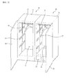
- FIG. 1 illustrates a perspective view of a multi-clothes styler system.
- the multi-clothes styler system is characterized in that a plurality of cabinet type clothes stylers 10 and 20 are connected in succession for increasing an amount of clothes to be treated.
- the multi-clothes styler system of the present invention includes a first clothes styler 10 and a second clothes styler 20.
- the clothes styler 10 or 20 includes a cabinet 11 or 21 for forming an exterior appearance of the clothes styler, and a treating chamber 12 or 22 in the cabinet 11 or 21 for housing the clothes. And, the clothes styler 10 or 20 also includes a door 13 or 33 mounted to a front of the cabinet 11 or 21 for isolating the treating chamber 12 or 22 from an outside of the cabinet, or opening the treating chamber 12 or 22 to the outside of the treating chamber 12 or 22, and a hanger 15 or 25 mounted to one side of the treating chamber 12 or 22 for hanging the clothes therefrom.
- the clothes styler 10 or 20 of the present invention is characterized in that the clothes are not placed on a bottom, but hung from an upper side or a side thereof.
- the treating chamber 12 or 22 is a space for applying hot air or steam to the clothes housed therein to change physical or chemical properties of the clothes. That is, the clothes may be dried by applying the hot air thereto, or the rumple on the clothes may be smoothed out by using the steam. Or, the clothes may have an aromatic agent sprayed thereto to make the clothes to give out a sweet smell, or antistatic agent sprayed thereto for preventing the clothes from being charged with static electricity.
- the treating chamber 12 or 22 is a space for treating the clothes by a variety of methods.
- the hanger 15 or 25 may have, but not limited to, a rod shape for hanging the clothes hanger 18 or 28 therefrom.
- the hanger 15 or 25 of the present invention has vibration applied thereto for enhancing a clothes treating effect.
- a driving unit positioned on one side of the treating chamber 12 or 22 converts rotation power of a motor into a vibratory movement in one or two axes directions by using a pulley or the like.
- the vibratory movement of the hanger 15 or 25 enhances an effect of smoothing out the rumples on the clothes and helps the steam and the hot air infiltrate into the clothes, better.
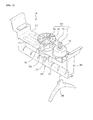
- FIGS. 2 and 3 illustrate movable hangers 50 the vibration can be applied thereto respectively, which are vibratory hangers 50 applicable to both of the first hanger 15 and the second hanger 25.
- FIG. 2 illustrates a perspective view of the movable hanger 50 in a multi-clothes styler system in accordance with a preferred embodiment of the present invention
- FIG. 3 illustrates an exploded perspective view of the movable hanger 50 of a multi-clothes styler system in accordance with a preferred embodiment of the present invention.
- the movable hanger 50 includes a hanger bar 250 for supporting a clothes hanger 200 having the clothes hung therefrom, and a supporter 280 for supporting both ends of the hanger bar 250.
- the hanger bar 250 has a plurality of clothes hanger grooves 251 provided therein for positioning the clothes hanger 200 when the clothes hanger 200 is placed thereon.
- the supporter 280 is connected to, and supported by, a movable hanger frame 213 provided to an upper side of an inside of ceiling of the cabinet 11 or 21 invisible from an outside of the cabinet 11 or 21.
- the hanger bar 250 has both ends provided with supporter ribs 254 to surround, and to be connected to, the supporter 280, respectively.
- the clothes styler of the present invention since the clothes styler of the present invention has the clothes placed therein hung from the clothes hanger, the clothes styler has effects much better than the related art clothes styler, not only in refreshing, but also in drying efficiency of the clothes.
- the movable hanger 50 includes a motor 230, a power converter 260 for converting rotating movement from the motor 230 to a horizontal linear movement of the hanger bar 250, and a power transmitter 240 for transmission of the power from the motor 230 to the power converter 260.
- the power transmitter 240 may include a driving pulley 241 provided to the motor 230, a driven pulley 242 connected to the driving pulley 241 with a belt 243, and a rotating shaft 244 coupled to a center of the driven pulley 242.
- the rotating shaft 244 is rotatably mounted in a bearing housing 270 provided to the movable hanger frame 213.
- the hanger bar 250 further includes a slot 252 perpendicular to a length direction of the hanger bar 250.
- the hanger bar 250 has a slot housing 254 over the hanger bar 250, with the slot 252 provided in the slot housing 253 at a center thereof, substantially.
- the power converter 260 may include a slot pin 263 placed in the slot 252, a shaft coupler 261 coupled to the rotating shaft 244, and a rotatable arm 262 connected between the slot pin 263 and the shaft coupler 261.
- the power converter 260 is covered with a cover 214 to make the power converter 260 invisible from an outside of the movable hanger 50 provided between the movable hanger frame 213 and the slot housing 253.
- the driven pulley 242 rotates to rotates the rotating shaft 244 coupled to the driven pulley 242 too, such that the slot pin 263 makes a circular motion with a predetermined diameter.
- the slot 252 is provided to the hanger bar 250 perpendicular to a length direction of the hanger bar 250, with a length thereof longer than a rotating locus of the slot pin 263. Therefore, even if the slot pin 263 makes circular motion, the slot 252 makes a horizontal linear motion. According to this, the hanger bar 250 coupled to the slot 250 makes the horizontal linear motion, too.
- a machinery room 26 is provided to one side of the treating chamber 22 to have an air supply unit 40 or a mist producing unit 30 for supplying the hot air or the steam to an inside of the treating chamber 12 or 22.
- FIG. 1 illustrates the machinery room 26 provided only to the second clothes styler 20, but the embodiment does not limit this, and the machinery room 26 may be provided only to the first clothes styler 10 or both of the clothes stylers 10 and 20. If the machinery room 26 is provided only to one side clothes styler 20, a duct or the like is connected from the one side styler 20 to the other side styler for supplying the steam or the hot air to the other side clothes styler through the duct.
- the machinery room 26 is positioned under the treating chamber 22, and has the air supply unit 40 and the mist producing unit 30 therein.
- the machinery room 26 is positioned under the treating chamber 22 because it is preferable that the treating room 22 is positioned under the machinery room 26 to supply the hot air and the steam by using a nature of rising of the hot air and the steam being supplied to the treating chamber 22.
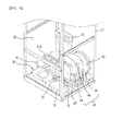
- FIG. 4 illustrates a perspective view of an inside of the machinery room, schematically.
- FIG. 4 illustrates a frame 21' of the cabinet 21 only, for convenience of view.
- FIG. 4 illustrates major elements, including the air supply unit 40 and the mist producing unit 30, but not pipelines which connect the major elements.
- the air supply unit 40 for supplying air or the hot air to the treating chamber 12 or 22.
- a heat pump 42 which is the air supply unit of the present invention has an evaporator 44, a compressor 46, a condenser 48, and an expansion valve (Not shown) for circulating refrigerant to dehumidify and heat the air.
- the refrigerant vaporizes at the evaporator 44, the refrigerant absorbs latent heat from surrounding air to cool down the air to condense moisture in the air, thereby removing the moisture from the air. And, if the refrigerant from the compressor 46 is introduced to, and condensed at, the condenser 48, the refrigerant discharges the latent heat to surrounding air to heat the surrounding air. According to this, since the evaporator 44 and the condenser 48 function as heat exchangers, the air introduced to the machinery room 26 has moisture thereof removed, or is heated, and supplied to the treating chamber 12 or 22.
- the air heated by the heat pump 42 may have a temperature more or less lower than the air heated by a related art electric heater, the heat pump 42 can remove the moisture from the air without using a dehumidifier, additionally. Therefore, the air supplied to the treating chamber 12 or 22 by the heat pump 42 is 'low temperature air' relatively (In this case, the 'low temperature' means, not an absolutely low temperature, but a relatively low temperature compared to a related art heated air, though the air is heated air).
- the clothes styler in accordance with a preferred embodiment of the present invention can prevent the clothes from distorting or damaging by a high temperature if clothes refreshing or drying is performed by supplying the low temperature air.
- the air supplied by the heat pump 42 has a temperature lower than the hot air of the related art clothes styler, since the clothes styler in accordance with a preferred embodiment of the present invention supplies the air having the moisture removed therefrom without the dehumidifier, easy drying or refreshing of the clothes is possible.
- the machinery room 26 has an air inlet 41A (See FIG. 4 ) formed in an upper side of a front thereof for introducing the air from the treating chamber 12 or 22 thereto, and an introduction duct 29 connecting the air inlet 41A to the evaporator 44, the condenser 48, and the fan 42 forms a flow passage for flowing the air.
- the air introduced to the machinery room 26 through the introduction duct 49 and the air inlet 41A has the moisture removed therefrom and heated as the air passes through the heat pump 42, and is supplied to the treating chamber 12 or 22 through a discharge duct 43 and an air outlet 418 by the fan 42, again.
- the air inlet 41A may have a filter provided thereto.
- various foreign matters may be filtered from the air introduced to the machinery room 26 from the treating chamber 12 or 22, to enable to supply only fresh air to the treating chamber 12 or 22.
- the machinery room 26 has the mist producing unit 30 provided thereto for supplying the moisture of mist, the mist or the steam (Hereafter, 'steam') to the treating chamber 12 or 22, selectively.
- the mist producing unit 30 has a heater (Not shown) provided therein for heating the water to produce the steam to be supplied to the treating chamber 12 or 22.
- a water supply source for supplying the water to the mist producing unit 30 an external water faucet may be used or a water supply tank (Not shown) provided to one side of the machinery room 26 may be used.
- the steam produced from the mist producing unit 30 is supplied to the treating chamber 12 or 22 through a steam hose 36 and a steam nozzle 40 (See FIGS. 1 and 2 ).
- the steam hose 36 is short. Accordingly, if the machinery room 26 is positioned under the treating chamber 12 or 22, it is preferable that the steam nozzle 40 supplies the steam through an upper side of the machinery room 26, i.e., an underside of the treating chamber 12 or 22.
- the machinery room 26 may have a circulating fan (Not shown) provided to a rear thereof.
- the circulating fan supplies the air to the machinery room 26 from an outside of the machinery room 26 for preventing a temperature of an inside of the machinery room 26 from rising excessively due to operation of the heat pump 42 and the mist producing unit 30.
- the multi-clothes styler system treats the clothes in spaces independent from one another, if the hanger 15 or 25 vibrates at a time, the vibration is liable to amplify as shown in FIG. 5 .
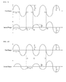
- FIG. 6 illustrates graphs showing vibration behavior of a first clothes styler 10 and vibration behavior of a second clothe styler 20, each of which vibrates with a predetermined amplitude A and B. If phases of the vibration are the same, to amplify the vibration as shown in FIG. 7 , noise becomes large to apply a heavy impact to the clothes styler resulting in damage to the clothes styler.
- the present invention relates to a method for operating a multi-clothes styler system for preventing the vibration from amplifying in a case the first clothes styler 10 and the second clothes styler 20 are operated at the same time.
- the multi-clothes styler system includes a control unit for controlling vibration of the first hanger and the second hanger.
- control of vibration frequencies and amplitude of the first hanger and the second hanger is performed by the control unit.
- FIG. 8 illustrates a flow chart showing the steps of a method for operating a multi-clothes styler system in accordance with a first preferred embodiment of the present invention.
- the first hanger 15 of the first clothes styler 10, and the second hanger 25 of the second clothes styler 20 are in operation or not at the same time (S100). If yes, it is determined whether vibration frequencies of the hangers 15 and 25 are the same or not (S200).
- the vibration frequency relates to vibration frequency and cycle of the motor 230 which operates the hanger, and if the vibration frequencies are the same, periods of vibration cycles are the same which are liable to amplify the vibration.
- the hangers which vibrate at the same vibration frequency have the same cycle period and the same vibration frequency of the motor.
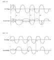
- the cycles of the hangers 15 and 25 shown in FIGS. 6 and 7 have the same cycle periods of 2x and the same vibration frequencies, respectively.
- a case in which phases of the vibration of the first hanger 15 of the first clothes styler 10 and the vibration of the second hanger 25 of the second clothes styler 20 are the same to have the same direction of the vibration as shown in FIGS. 6 and 7 , to add the two vibrations to increase amplitude thereof is called as an inphase, and opposite to this, another case in which, though the cycles are the same, the directions of the vibrations are opposite, is called as an antiphase.
- an extent of amplification of the vibration becomes higher to cause a problem in that noise and impact applied to the clothes stylers 10 and 20 is intense.
- the vibrations offsets each other to make the amplitude smaller the noise may be reduced smaller than one hanger vibrates as the vibration offsets.
- FIGS. 9 to 11 illustrate methods for controlling a multi-clothes styler system if the vibration frequencies are the same, i.e., the cycles are the same, respectively.
- the vibrations of the first hanger 15 and the second hanger 25 are inphase initially, the vibrations are controlled to be an antiphase in a later half (After T2 of Fig. 9 or T5). Especially, if the vibrations are controlled to make the amplitudes of the first hanger 15 and the second hanger 25 to be the same (After T3), entire vibrations are offset, completely.
- an antiphase can be made. That is, after stopping the second hanger 25 for a certain time period, the vibration of the second hanger 25 may be started at a time point the phase of the second hanger 25 is opposite to the phase of the first hanger 15.
- the antiphase can be made by delaying half cycle x.
- the phases are not the inphase, but vary slightly with a difference of a time delay of w, operation of the second hanger 25 is delayed until the antiphase is made.
- operation of the second hanger 25 is controlled such that the vibration frequency of the second hanger 25 is changed temporarily, to make the vibration phase of the second hanger 25 to be an antiphase with the vibration phase of the first hanger 15.
- the antiphase control may include a frequency change step in which at least one of the vibration frequencies of the first hanger 15 and the second hanger 25 is changed and a frequency synchronizing step in which frequencies of the first hanger 15 and the second hanger 25 are made to coincide.
- a change of the frequency of the second hanger 25 is described as an example, it is apparent that frequencies both of the two hangers may be changed.
- the frequency is made low, a period of the cycle becomes long, to increase the period of the cycle from 2x to 2y as shown in FIG. 11 .
- the vibration frequencies are made the same from a moment (T2 or T3) the directions of the vibrations of the first hanger 15 and the second hanger 25 are opposite, the first hanger 15 and the second hanger 25 vibrate in the antiphase state, to make an entire vibration minimum.
- the time point the frequency change step is performed is a time point (A starting point in FIG. 11 ) when the vibration frequencies of the first hanger 15 and the second hanger 25 are end at the same time.
- the vibration frequency of the first hanger 15 may be changed to (2n+1)/2 of the vibration frequency of the second hanger.
- the vibration frequency of the second hanger 25 may be changed to an n of the vibration frequency of the first hanger 15.
- the n denotes 0 or a natural number.
- the frequency synchronizing step is performed. It is preferable that the frequency synchronizing step is performed at a time point T5 when the phases of the first hanger 15 and the second hanger 25 are opposite to each other and the vibration frequencies end at the same time. If the frequency change step is performed, the vibration frequencies of the first hanger 15 and the second hanger 25 end at the same time point T5 after a certain time period is passed. Of the time points when the vibration frequencies of the first hanger 15 and the second hanger 25 end at the same time point thus, the frequency synchronizing step is performed at the time point the phases of the first hanger 15 and the second hanger 25 are opposite to each other. Therefore, the first hanger 15 and the second hanger 25 may be controlled to be in the antiphase.
- This method is also applicable even if the first hanger 15 and the second hanger 25 are not in the antiphase, initially. In the meantime, if the amplitudes of the first hanger 15 and the second hanger 25 are different, an amplitude synchronizing step may further be performed, to make the amplitudes of the two hangers to coincide.
- the amplitude synchronizing step may be performed before or after the antiphase control step, preferably after the antiphase control step.
- an inphase preventive step (S400) is performed, which is characterized in that the second hanger 25 is controlled for preventing the vibration phase of the second hanger 25 from being an inphase of the vibration phase of the first hanger 15.
- the inphase preventive step (S400) may include the frequency synchronizing step in which at least one of vibration frequencies of the first hanger 15 and the second hanger 25 is changed to make the vibration frequencies of the first hanger 15 and the second hanger 25 to coincide. It is preferable that the frequency synchronizing step is performed at a time point the vibration frequencies of the first hanger 15 and the second hanger 25 are finished at the same time.
- FIG. 12 illustrates a graph showing the inphase preventive step in a method for operating a multi-clothes styler system in accordance with a third preferred embodiment of the present invention, wherein the inphase preventive step (S400) is performed since the vibration frequencies of the first hanger 15 and the second hanger 25 are not the same, initially.
- the inphase preventive step (S400) may includes the frequency synchronizing step and a delay step in which the vibration of the second hanger is stopped for a certain time period.
- the frequency synchronizing step is performed at a time point the vibration frequencies of the first hanger 15 and the second hanger 25 end at the same time.
- the frequency synchronizing step is performed, if the phases of the first hanger 15 and the second hanger 25 are the same, it is preferable that the vibration of the second hanger stops for (2n+1)/2 cycles in the delay step, where the n denotes 0 or a natural number. In the meantime, if the phases of the first hanger 15 and the second hanger 25 are opposite at the time point the frequency synchronizing step is performed, the delay step may be omitted.
- the vibration frequency of the second hanger 25 is changed, to coincide with the vibration frequency of the first hanger 15 (A T7 to T8 section), and operation of the second hanger 25 is delayed to make the vibration frequency of the second hanger 25 becomes an antiphase of the vibration frequency of the first hanger 15 (After T8).
- the vibration of the second hanger 25 is delayed by half cycle, to control the phase of the second hanger 25 to be an antiphase of the phase of the first hanger 15, the vibrations are offset.
- the delay step may be omitted. That is, when a direction of the vibration of the second hanger 25 is opposite to the direction of the vibration of the first hanger 15 T9, the vibration frequencies of the first hanger 15 and the second hanger 25 are made the same, to control the phase of the first hanger is antiphase of the phase of the second hanger.
- the inphase preventive step (S400) may also include the amplitude synchronizing step for controlling the second hanger 25 to control the amplitude of the second hanger to be the same with the amplitude of the first hanger 15 if the amplitude of the first hanger 15 is different from the amplitude of the second hanger 25, for enhancing a vibration offsetting effect.
- the method for operating a multi-clothes styler system of the present invention can minimize noise produced when the hangers vibrate and can prevent a lifetime of the multi-clothes styler system from reducing due to intensive vibration.
Landscapes
- Engineering & Computer Science (AREA)
- Textile Engineering (AREA)
- Accessory Of Washing/Drying Machine, Commercial Washing/Drying Machine, Other Washing/Drying Machine (AREA)
- Control Of Washing Machine And Dryer (AREA)
Applications Claiming Priority (1)
| Application Number | Priority Date | Filing Date | Title |
|---|---|---|---|
| KR1020110103139A KR101819511B1 (ko) | 2011-10-10 | 2011-10-10 | 다중 의류처리 시스템의 구동방법 |
Publications (2)
| Publication Number | Publication Date |
|---|---|
| EP2581487A1 true EP2581487A1 (fr) | 2013-04-17 |
| EP2581487B1 EP2581487B1 (fr) | 2014-12-03 |
Family
ID=47257434
Family Applications (1)
| Application Number | Title | Priority Date | Filing Date |
|---|---|---|---|
| EP12187264.2A Active EP2581487B1 (fr) | 2011-10-10 | 2012-10-04 | Procédé de fonctionnement d'un système de coiffage de plusieurs vêtements |
Country Status (8)
| Country | Link |
|---|---|
| US (1) | US8707591B2 (fr) |
| EP (1) | EP2581487B1 (fr) |
| JP (1) | JP5486063B2 (fr) |
| KR (1) | KR101819511B1 (fr) |
| CN (1) | CN103027558B (fr) |
| AU (1) | AU2012227348B2 (fr) |
| DE (1) | DE202012009608U1 (fr) |
| TW (1) | TWI454229B (fr) |
Cited By (2)
| Publication number | Priority date | Publication date | Assignee | Title |
|---|---|---|---|---|
| US20140317948A1 (en) * | 2013-04-25 | 2014-10-30 | Lg Electronics Inc. | Laundry treating apparatus |
| EP3964642A1 (fr) * | 2020-09-04 | 2022-03-09 | LG Electronics Inc. | Appareil de traitement de vêtements |
Families Citing this family (24)
| Publication number | Priority date | Publication date | Assignee | Title |
|---|---|---|---|---|
| KR101295579B1 (ko) * | 2011-11-15 | 2013-08-09 | 엘지전자 주식회사 | 의류처리장치 및 그 제어방법 |
| JP6295427B2 (ja) * | 2014-06-17 | 2018-03-20 | パナソニックIpマネジメント株式会社 | 布材処理装置 |
| KR101600788B1 (ko) * | 2014-10-29 | 2016-03-08 | 양준식 | 의복 리프레쉬 장치 |
| CN104490109A (zh) * | 2014-11-27 | 2015-04-08 | 湖南中医药大学 | 中药衣柜底垫 |
| US9613516B2 (en) | 2015-03-19 | 2017-04-04 | Ebay Inc. | System and methods for soiled garment detection and notification |
| CN106149326B (zh) * | 2016-06-03 | 2019-01-25 | 无锡小天鹅股份有限公司 | 衣物护理机 |
| KR102003820B1 (ko) * | 2017-12-08 | 2019-07-25 | 엘지전자 주식회사 | 의류 처리 장치 |
| CN108277627A (zh) * | 2018-03-26 | 2018-07-13 | 宁波奥达智能家居有限公司 | 一种全自动耐熨烫晾衣柜 |
| CN110878472B (zh) * | 2018-09-05 | 2025-01-24 | 广东美的白色家电技术创新中心有限公司 | 衣撑、衣撑组件及衣物护理设备 |
| CN110878468B (zh) * | 2018-09-05 | 2022-03-01 | 广东美的白色家电技术创新中心有限公司 | 衣物护理设备、衣物护理设备的控制方法 |
| KR102769000B1 (ko) * | 2019-08-30 | 2025-02-14 | 엘지전자 주식회사 | 의류 포질에 따라 의류 처리 코스를 제어하는 방법, 장치 및 시스템 |
| JP7453645B2 (ja) * | 2019-12-25 | 2024-03-21 | 青島海爾洗衣机有限公司 | 衣類処理装置 |
| KR20220031333A (ko) * | 2020-09-04 | 2022-03-11 | 엘지전자 주식회사 | 의류처리장치 |
| JP7060270B1 (ja) | 2020-11-09 | 2022-04-26 | ワイズプラント株式会社 | 業務用衣類処理装置 |
| KR102641643B1 (ko) * | 2020-12-30 | 2024-02-28 | 광동 갈란즈 엔터프라이지즈 컴퍼니 리미티드 | 의류 셰이킹 장치 및 그의 의류 무빙 제어방법 |
| KR20220111110A (ko) * | 2021-02-01 | 2022-08-09 | 삼성전자주식회사 | 의류관리기 |
| KR102525463B1 (ko) | 2021-04-05 | 2023-04-24 | 에스케이매직 주식회사 | 의류처리장치 및 이의 옷걸이 |
| JP1751000S (ja) * | 2021-05-21 | 2023-08-17 | 衣服用除湿脱臭及びしわ除去機の本体 | |
| USD1011659S1 (en) * | 2021-08-04 | 2024-01-16 | Samsung Electronics Co., Ltd. | Clothing care machine |
| KR102838595B1 (ko) * | 2022-01-05 | 2025-07-25 | 엘지전자 주식회사 | 의류처리장치 |
| AU2024330187A1 (en) * | 2023-08-30 | 2026-03-05 | Lg Electronics Inc. | Clothing treatment apparatus |
| AU2024334163A1 (en) * | 2023-08-30 | 2026-03-19 | Lg Electronics Inc. | Clothes treatment apparatus |
| EP4756112A1 (fr) * | 2023-08-30 | 2026-06-10 | LG Electronics Inc. | Appareil de traitement de vêtements |
| KR20250108443A (ko) * | 2024-01-08 | 2025-07-15 | 엘지전자 주식회사 | 의류처리장치 |
Citations (5)
| Publication number | Priority date | Publication date | Assignee | Title |
|---|---|---|---|---|
| US20060037209A1 (en) * | 2004-08-18 | 2006-02-23 | Maytag Corporation | Drying cabinet shaker mechanism |
| WO2010082759A2 (fr) * | 2009-01-15 | 2010-07-22 | Lg Electronics Inc. | Appareil de traitement pour lessive |
| WO2011108865A2 (fr) * | 2010-03-03 | 2011-09-09 | Lg Electronics Inc. | Appareil de traitement du linge |
| WO2011108860A2 (fr) * | 2010-03-03 | 2011-09-09 | Lg Electronics Inc. | Appareil de traitement de vêtements et son procédé de commande |
| KR20120033034A (ko) * | 2010-09-29 | 2012-04-06 | 주식회사 더블유케이마케팅 | 대칭 진동 세탁물 건조대 |
Family Cites Families (27)
| Publication number | Priority date | Publication date | Assignee | Title |
|---|---|---|---|---|
| US1602315A (en) * | 1925-05-09 | 1926-10-05 | Ideal Filter Company | Clothes drier |
| US3114919A (en) * | 1961-01-06 | 1963-12-24 | Whirlpool Co | Method and apparatus for shaking a garment and applying cleaning liquid and drying fluid thereto |
| US3739496A (en) * | 1971-03-24 | 1973-06-19 | Mc Graw Edison Co | Steam air cabinet finisher |
| GB1351155A (en) * | 1971-07-27 | 1974-04-24 | Gillette Co | Electric shavers |
| US4682424A (en) * | 1986-10-16 | 1987-07-28 | Arlillian Irving | Clothes drying apparatus |
| US4930113A (en) * | 1989-03-30 | 1990-05-29 | Halliburton Geophysical Services, Inc. | Suppression of air-coupled noise produced by seismic vibrators |
| US7103996B2 (en) * | 2002-05-15 | 2006-09-12 | Ark-Les Corporation | Agitator for removing wrinkles from clothing |
| CN1465311A (zh) * | 2002-06-18 | 2004-01-07 | 君 金 | 多功能衣柜 |
| US20050223502A1 (en) * | 2004-04-09 | 2005-10-13 | Kleker Richard G | Apparatus for processing garments including a hanger mechanism |
| JP3914514B2 (ja) * | 2003-05-21 | 2007-05-16 | 日立アプライアンス株式会社 | 洗濯機 |
| CN2649627Y (zh) * | 2003-07-09 | 2004-10-20 | 陆元坤 | 一种密闭式逆流吹淋除湿干衣装置 |
| US7097051B2 (en) * | 2003-08-15 | 2006-08-29 | Maytag Corporation | Hanger rod for drying cabinet |
| CN2657479Y (zh) * | 2003-11-21 | 2004-11-24 | 萧耀光 | 多功能衣柜 |
| JP3744930B1 (ja) | 2004-11-08 | 2006-02-15 | マグ末広工業株式会社 | 衣類の乾燥装置 |
| JP2006255302A (ja) | 2005-03-18 | 2006-09-28 | Sr Engineering Co Ltd | クリーニング装置 |
| TWM270722U (en) * | 2005-03-29 | 2005-07-21 | Shr-Kuan Lai | Improvement of wardrobe structure |
| TW200904360A (en) * | 2007-07-27 | 2009-02-01 | Wu-Jin Lin | Drying type closet structure |
| KR101430457B1 (ko) * | 2007-11-12 | 2014-08-18 | 엘지전자 주식회사 | 의류처리장치 |
| JP5433969B2 (ja) | 2008-04-08 | 2014-03-05 | パナソニック株式会社 | 脱臭装置 |
| US8296967B2 (en) * | 2008-12-09 | 2012-10-30 | Lg Electronics Inc. | Fabric treating apparatus |
| KR101608656B1 (ko) * | 2009-09-29 | 2016-04-04 | 엘지전자 주식회사 | 의류 처리 장치 및 의류 처리 장치 |
| JP5514221B2 (ja) * | 2010-02-23 | 2014-06-04 | パナソニック株式会社 | 圧電型音響変換器 |
| KR101710392B1 (ko) * | 2010-03-03 | 2017-02-27 | 엘지전자 주식회사 | 의류처리장치 |
| US8523264B2 (en) * | 2010-04-14 | 2013-09-03 | Nissan Motor Co., Ltd. | Windshield glass support structure |
| CN201738157U (zh) * | 2010-07-06 | 2011-02-09 | 刘树华 | 能复平湿衣折皱的干衣柜 |
| CN201782313U (zh) * | 2010-08-26 | 2011-04-06 | 谢德炜 | 一种多功能储物柜 |
| CN201915270U (zh) * | 2011-01-24 | 2011-08-03 | 常德家保科技有限公司 | 毛巾、衣物烘干消毒柜 |
-
2011
- 2011-10-10 KR KR1020110103139A patent/KR101819511B1/ko active Active
-
2012
- 2012-09-26 AU AU2012227348A patent/AU2012227348B2/en not_active Ceased
- 2012-10-04 EP EP12187264.2A patent/EP2581487B1/fr active Active
- 2012-10-08 TW TW101137124A patent/TWI454229B/zh not_active IP Right Cessation
- 2012-10-09 DE DE202012009608U patent/DE202012009608U1/de not_active Expired - Lifetime
- 2012-10-09 US US13/647,976 patent/US8707591B2/en active Active
- 2012-10-10 JP JP2012225269A patent/JP5486063B2/ja not_active Expired - Fee Related
- 2012-10-10 CN CN201210383226.5A patent/CN103027558B/zh active Active
Patent Citations (5)
| Publication number | Priority date | Publication date | Assignee | Title |
|---|---|---|---|---|
| US20060037209A1 (en) * | 2004-08-18 | 2006-02-23 | Maytag Corporation | Drying cabinet shaker mechanism |
| WO2010082759A2 (fr) * | 2009-01-15 | 2010-07-22 | Lg Electronics Inc. | Appareil de traitement pour lessive |
| WO2011108865A2 (fr) * | 2010-03-03 | 2011-09-09 | Lg Electronics Inc. | Appareil de traitement du linge |
| WO2011108860A2 (fr) * | 2010-03-03 | 2011-09-09 | Lg Electronics Inc. | Appareil de traitement de vêtements et son procédé de commande |
| KR20120033034A (ko) * | 2010-09-29 | 2012-04-06 | 주식회사 더블유케이마케팅 | 대칭 진동 세탁물 건조대 |
Cited By (7)
| Publication number | Priority date | Publication date | Assignee | Title |
|---|---|---|---|---|
| US20140317948A1 (en) * | 2013-04-25 | 2014-10-30 | Lg Electronics Inc. | Laundry treating apparatus |
| US9359710B2 (en) * | 2013-04-25 | 2016-06-07 | Lg Electronics Inc. | Laundry treating apparatus |
| EP3964642A1 (fr) * | 2020-09-04 | 2022-03-09 | LG Electronics Inc. | Appareil de traitement de vêtements |
| US11976412B2 (en) | 2020-09-04 | 2024-05-07 | Lg Electronics Inc. | Clothes treatment apparatus |
| AU2021336001B2 (en) * | 2020-09-04 | 2024-11-07 | Lg Electronics Inc. | Clothes treatment apparatus |
| AU2021336001C1 (en) * | 2020-09-04 | 2025-02-20 | Lg Electronics Inc. | Clothes treatment apparatus |
| US12344990B2 (en) | 2020-09-04 | 2025-07-01 | Lg Electronics Inc. | Clothes treatment apparatus |
Also Published As
| Publication number | Publication date |
|---|---|
| US8707591B2 (en) | 2014-04-29 |
| CN103027558B (zh) | 2014-12-17 |
| TWI454229B (zh) | 2014-10-01 |
| JP2013081782A (ja) | 2013-05-09 |
| CN103027558A (zh) | 2013-04-10 |
| US20130086830A1 (en) | 2013-04-11 |
| JP5486063B2 (ja) | 2014-05-07 |
| TW201315411A (zh) | 2013-04-16 |
| KR20130038659A (ko) | 2013-04-18 |
| KR101819511B1 (ko) | 2018-01-17 |
| AU2012227348A1 (en) | 2013-05-02 |
| EP2581487B1 (fr) | 2014-12-03 |
| DE202012009608U1 (de) | 2013-01-18 |
| AU2012227348B2 (en) | 2014-02-13 |
Similar Documents
| Publication | Publication Date | Title |
|---|---|---|
| EP2581487B1 (fr) | Procédé de fonctionnement d'un système de coiffage de plusieurs vêtements | |
| US12590401B2 (en) | Laundry treating apparatus | |
| AU2010205103B2 (en) | Laundry treating apparatus | |
| KR101053631B1 (ko) | 의류처리장치 | |
| US8484868B2 (en) | Laundry treating apparatus | |
| CN101666031A (zh) | 干燥机及洗涤干燥机 | |
| KR101191205B1 (ko) | 의류처리장치의 제어방법 | |
| KR20110127426A (ko) | 의류처리장치 | |
| KR20110137468A (ko) | 의류처리장치 |
Legal Events
| Date | Code | Title | Description |
|---|---|---|---|
| PUAI | Public reference made under article 153(3) epc to a published international application that has entered the european phase |
Free format text: ORIGINAL CODE: 0009012 |
|
| AK | Designated contracting states |
Kind code of ref document: A1 Designated state(s): AL AT BE BG CH CY CZ DE DK EE ES FI FR GB GR HR HU IE IS IT LI LT LU LV MC MK MT NL NO PL PT RO RS SE SI SK SM TR |
|
| AX | Request for extension of the european patent |
Extension state: BA ME |
|
| 17P | Request for examination filed |
Effective date: 20130528 |
|
| RBV | Designated contracting states (corrected) |
Designated state(s): AL AT BE BG CH CY CZ DE DK EE ES FI FR GB GR HR HU IE IS IT LI LT LU LV MC MK MT NL NO PL PT RO RS SE SI SK SM TR |
|
| RIC1 | Information provided on ipc code assigned before grant |
Ipc: D06F 73/02 20060101ALI20131118BHEP Ipc: D06F 58/10 20060101AFI20131118BHEP |
|
| GRAP | Despatch of communication of intention to grant a patent |
Free format text: ORIGINAL CODE: EPIDOSNIGR1 |
|
| INTG | Intention to grant announced |
Effective date: 20140703 |
|
| RAP1 | Party data changed (applicant data changed or rights of an application transferred) |
Owner name: LG ELECTRONICS INC. |
|
| GRAS | Grant fee paid |
Free format text: ORIGINAL CODE: EPIDOSNIGR3 |
|
| GRAA | (expected) grant |
Free format text: ORIGINAL CODE: 0009210 |
|
| RAP1 | Party data changed (applicant data changed or rights of an application transferred) |
Owner name: LG ELECTRONICS INC. |
|
| AK | Designated contracting states |
Kind code of ref document: B1 Designated state(s): AL AT BE BG CH CY CZ DE DK EE ES FI FR GB GR HR HU IE IS IT LI LT LU LV MC MK MT NL NO PL PT RO RS SE SI SK SM TR |
|
| REG | Reference to a national code |
Ref country code: GB Ref legal event code: FG4D |
|
| REG | Reference to a national code |
Ref country code: AT Ref legal event code: REF Ref document number: 699459 Country of ref document: AT Kind code of ref document: T Effective date: 20141215 Ref country code: CH Ref legal event code: EP |
|
| REG | Reference to a national code |
Ref country code: IE Ref legal event code: FG4D |
|
| REG | Reference to a national code |
Ref country code: DE Ref legal event code: R096 Ref document number: 602012004081 Country of ref document: DE Effective date: 20150115 |
|
| REG | Reference to a national code |
Ref country code: NL Ref legal event code: VDEP Effective date: 20141203 |
|
| REG | Reference to a national code |
Ref country code: AT Ref legal event code: MK05 Ref document number: 699459 Country of ref document: AT Kind code of ref document: T Effective date: 20141203 |
|
| PG25 | Lapsed in a contracting state [announced via postgrant information from national office to epo] |
Ref country code: FI Free format text: LAPSE BECAUSE OF FAILURE TO SUBMIT A TRANSLATION OF THE DESCRIPTION OR TO PAY THE FEE WITHIN THE PRESCRIBED TIME-LIMIT Effective date: 20141203 Ref country code: NO Free format text: LAPSE BECAUSE OF FAILURE TO SUBMIT A TRANSLATION OF THE DESCRIPTION OR TO PAY THE FEE WITHIN THE PRESCRIBED TIME-LIMIT Effective date: 20150303 Ref country code: NL Free format text: LAPSE BECAUSE OF FAILURE TO SUBMIT A TRANSLATION OF THE DESCRIPTION OR TO PAY THE FEE WITHIN THE PRESCRIBED TIME-LIMIT Effective date: 20141203 Ref country code: ES Free format text: LAPSE BECAUSE OF FAILURE TO SUBMIT A TRANSLATION OF THE DESCRIPTION OR TO PAY THE FEE WITHIN THE PRESCRIBED TIME-LIMIT Effective date: 20141203 Ref country code: LT Free format text: LAPSE BECAUSE OF FAILURE TO SUBMIT A TRANSLATION OF THE DESCRIPTION OR TO PAY THE FEE WITHIN THE PRESCRIBED TIME-LIMIT Effective date: 20141203 |
|
| REG | Reference to a national code |
Ref country code: LT Ref legal event code: MG4D |
|
| PG25 | Lapsed in a contracting state [announced via postgrant information from national office to epo] |
Ref country code: HR Free format text: LAPSE BECAUSE OF FAILURE TO SUBMIT A TRANSLATION OF THE DESCRIPTION OR TO PAY THE FEE WITHIN THE PRESCRIBED TIME-LIMIT Effective date: 20141203 Ref country code: CY Free format text: LAPSE BECAUSE OF FAILURE TO SUBMIT A TRANSLATION OF THE DESCRIPTION OR TO PAY THE FEE WITHIN THE PRESCRIBED TIME-LIMIT Effective date: 20141203 Ref country code: GR Free format text: LAPSE BECAUSE OF FAILURE TO SUBMIT A TRANSLATION OF THE DESCRIPTION OR TO PAY THE FEE WITHIN THE PRESCRIBED TIME-LIMIT Effective date: 20150304 Ref country code: RS Free format text: LAPSE BECAUSE OF FAILURE TO SUBMIT A TRANSLATION OF THE DESCRIPTION OR TO PAY THE FEE WITHIN THE PRESCRIBED TIME-LIMIT Effective date: 20141203 Ref country code: LV Free format text: LAPSE BECAUSE OF FAILURE TO SUBMIT A TRANSLATION OF THE DESCRIPTION OR TO PAY THE FEE WITHIN THE PRESCRIBED TIME-LIMIT Effective date: 20141203 Ref country code: AT Free format text: LAPSE BECAUSE OF FAILURE TO SUBMIT A TRANSLATION OF THE DESCRIPTION OR TO PAY THE FEE WITHIN THE PRESCRIBED TIME-LIMIT Effective date: 20141203 Ref country code: SE Free format text: LAPSE BECAUSE OF FAILURE TO SUBMIT A TRANSLATION OF THE DESCRIPTION OR TO PAY THE FEE WITHIN THE PRESCRIBED TIME-LIMIT Effective date: 20141203 |
|
| PG25 | Lapsed in a contracting state [announced via postgrant information from national office to epo] |
Ref country code: PT Free format text: LAPSE BECAUSE OF FAILURE TO SUBMIT A TRANSLATION OF THE DESCRIPTION OR TO PAY THE FEE WITHIN THE PRESCRIBED TIME-LIMIT Effective date: 20150403 Ref country code: CZ Free format text: LAPSE BECAUSE OF FAILURE TO SUBMIT A TRANSLATION OF THE DESCRIPTION OR TO PAY THE FEE WITHIN THE PRESCRIBED TIME-LIMIT Effective date: 20141203 Ref country code: SK Free format text: LAPSE BECAUSE OF FAILURE TO SUBMIT A TRANSLATION OF THE DESCRIPTION OR TO PAY THE FEE WITHIN THE PRESCRIBED TIME-LIMIT Effective date: 20141203 Ref country code: EE Free format text: LAPSE BECAUSE OF FAILURE TO SUBMIT A TRANSLATION OF THE DESCRIPTION OR TO PAY THE FEE WITHIN THE PRESCRIBED TIME-LIMIT Effective date: 20141203 Ref country code: RO Free format text: LAPSE BECAUSE OF FAILURE TO SUBMIT A TRANSLATION OF THE DESCRIPTION OR TO PAY THE FEE WITHIN THE PRESCRIBED TIME-LIMIT Effective date: 20141203 |
|
| PG25 | Lapsed in a contracting state [announced via postgrant information from national office to epo] |
Ref country code: PL Free format text: LAPSE BECAUSE OF FAILURE TO SUBMIT A TRANSLATION OF THE DESCRIPTION OR TO PAY THE FEE WITHIN THE PRESCRIBED TIME-LIMIT Effective date: 20141203 Ref country code: IS Free format text: LAPSE BECAUSE OF FAILURE TO SUBMIT A TRANSLATION OF THE DESCRIPTION OR TO PAY THE FEE WITHIN THE PRESCRIBED TIME-LIMIT Effective date: 20150403 |
|
| REG | Reference to a national code |
Ref country code: DE Ref legal event code: R097 Ref document number: 602012004081 Country of ref document: DE |
|
| PLBE | No opposition filed within time limit |
Free format text: ORIGINAL CODE: 0009261 |
|
| STAA | Information on the status of an ep patent application or granted ep patent |
Free format text: STATUS: NO OPPOSITION FILED WITHIN TIME LIMIT |
|
| PG25 | Lapsed in a contracting state [announced via postgrant information from national office to epo] |
Ref country code: DK Free format text: LAPSE BECAUSE OF FAILURE TO SUBMIT A TRANSLATION OF THE DESCRIPTION OR TO PAY THE FEE WITHIN THE PRESCRIBED TIME-LIMIT Effective date: 20141203 |
|
| 26N | No opposition filed |
Effective date: 20150904 |
|
| PG25 | Lapsed in a contracting state [announced via postgrant information from national office to epo] |
Ref country code: SI Free format text: LAPSE BECAUSE OF FAILURE TO SUBMIT A TRANSLATION OF THE DESCRIPTION OR TO PAY THE FEE WITHIN THE PRESCRIBED TIME-LIMIT Effective date: 20141203 |
|
| REG | Reference to a national code |
Ref country code: DE Ref legal event code: R119 Ref document number: 602012004081 Country of ref document: DE |
|
| PG25 | Lapsed in a contracting state [announced via postgrant information from national office to epo] |
Ref country code: BE Free format text: LAPSE BECAUSE OF FAILURE TO SUBMIT A TRANSLATION OF THE DESCRIPTION OR TO PAY THE FEE WITHIN THE PRESCRIBED TIME-LIMIT Effective date: 20141203 Ref country code: LU Free format text: LAPSE BECAUSE OF FAILURE TO SUBMIT A TRANSLATION OF THE DESCRIPTION OR TO PAY THE FEE WITHIN THE PRESCRIBED TIME-LIMIT Effective date: 20151004 |
|
| REG | Reference to a national code |
Ref country code: CH Ref legal event code: PL |
|
| PG25 | Lapsed in a contracting state [announced via postgrant information from national office to epo] |
Ref country code: MC Free format text: LAPSE BECAUSE OF FAILURE TO SUBMIT A TRANSLATION OF THE DESCRIPTION OR TO PAY THE FEE WITHIN THE PRESCRIBED TIME-LIMIT Effective date: 20141203 |
|
| REG | Reference to a national code |
Ref country code: IE Ref legal event code: MM4A |
|
| PG25 | Lapsed in a contracting state [announced via postgrant information from national office to epo] |
Ref country code: CH Free format text: LAPSE BECAUSE OF NON-PAYMENT OF DUE FEES Effective date: 20151031 Ref country code: DE Free format text: LAPSE BECAUSE OF NON-PAYMENT OF DUE FEES Effective date: 20160503 Ref country code: LI Free format text: LAPSE BECAUSE OF NON-PAYMENT OF DUE FEES Effective date: 20151031 |
|
| REG | Reference to a national code |
Ref country code: FR Ref legal event code: PLFP Year of fee payment: 5 |
|
| PG25 | Lapsed in a contracting state [announced via postgrant information from national office to epo] |
Ref country code: IE Free format text: LAPSE BECAUSE OF NON-PAYMENT OF DUE FEES Effective date: 20151004 |
|
| PG25 | Lapsed in a contracting state [announced via postgrant information from national office to epo] |
Ref country code: HU Free format text: LAPSE BECAUSE OF FAILURE TO SUBMIT A TRANSLATION OF THE DESCRIPTION OR TO PAY THE FEE WITHIN THE PRESCRIBED TIME-LIMIT; INVALID AB INITIO Effective date: 20121004 Ref country code: SM Free format text: LAPSE BECAUSE OF FAILURE TO SUBMIT A TRANSLATION OF THE DESCRIPTION OR TO PAY THE FEE WITHIN THE PRESCRIBED TIME-LIMIT Effective date: 20141203 Ref country code: BG Free format text: LAPSE BECAUSE OF FAILURE TO SUBMIT A TRANSLATION OF THE DESCRIPTION OR TO PAY THE FEE WITHIN THE PRESCRIBED TIME-LIMIT Effective date: 20141203 |
|
| PG25 | Lapsed in a contracting state [announced via postgrant information from national office to epo] |
Ref country code: MT Free format text: LAPSE BECAUSE OF FAILURE TO SUBMIT A TRANSLATION OF THE DESCRIPTION OR TO PAY THE FEE WITHIN THE PRESCRIBED TIME-LIMIT Effective date: 20141203 |
|
| REG | Reference to a national code |
Ref country code: FR Ref legal event code: PLFP Year of fee payment: 6 |
|
| PGFP | Annual fee paid to national office [announced via postgrant information from national office to epo] |
Ref country code: GB Payment date: 20170906 Year of fee payment: 6 |
|
| PG25 | Lapsed in a contracting state [announced via postgrant information from national office to epo] |
Ref country code: TR Free format text: LAPSE BECAUSE OF FAILURE TO SUBMIT A TRANSLATION OF THE DESCRIPTION OR TO PAY THE FEE WITHIN THE PRESCRIBED TIME-LIMIT Effective date: 20141203 Ref country code: MK Free format text: LAPSE BECAUSE OF FAILURE TO SUBMIT A TRANSLATION OF THE DESCRIPTION OR TO PAY THE FEE WITHIN THE PRESCRIBED TIME-LIMIT Effective date: 20141203 |
|
| REG | Reference to a national code |
Ref country code: FR Ref legal event code: PLFP Year of fee payment: 7 |
|
| PG25 | Lapsed in a contracting state [announced via postgrant information from national office to epo] |
Ref country code: AL Free format text: LAPSE BECAUSE OF FAILURE TO SUBMIT A TRANSLATION OF THE DESCRIPTION OR TO PAY THE FEE WITHIN THE PRESCRIBED TIME-LIMIT Effective date: 20141203 |
|
| GBPC | Gb: european patent ceased through non-payment of renewal fee |
Effective date: 20181004 |
|
| PG25 | Lapsed in a contracting state [announced via postgrant information from national office to epo] |
Ref country code: GB Free format text: LAPSE BECAUSE OF NON-PAYMENT OF DUE FEES Effective date: 20181004 |
|
| PGFP | Annual fee paid to national office [announced via postgrant information from national office to epo] |
Ref country code: FR Payment date: 20220905 Year of fee payment: 11 |
|
| PG25 | Lapsed in a contracting state [announced via postgrant information from national office to epo] |
Ref country code: FR Free format text: LAPSE BECAUSE OF NON-PAYMENT OF DUE FEES Effective date: 20231031 |
|
| PGFP | Annual fee paid to national office [announced via postgrant information from national office to epo] |
Ref country code: IT Payment date: 20250909 Year of fee payment: 14 |