EP2581556A2 - Aubes variables avec inclinaison non uniforme - Google Patents
Aubes variables avec inclinaison non uniforme Download PDFInfo
- Publication number
- EP2581556A2 EP2581556A2 EP12188237.7A EP12188237A EP2581556A2 EP 2581556 A2 EP2581556 A2 EP 2581556A2 EP 12188237 A EP12188237 A EP 12188237A EP 2581556 A2 EP2581556 A2 EP 2581556A2
- Authority
- EP
- European Patent Office
- Prior art keywords
- stator vanes
- variable stator
- airfoils
- clockwise
- gas turbine
- Prior art date
- Legal status (The legal status is an assumption and is not a legal conclusion. Google has not performed a legal analysis and makes no representation as to the accuracy of the status listed.)
- Withdrawn
Links
- 238000000034 method Methods 0.000 claims description 11
- 238000004519 manufacturing process Methods 0.000 claims description 10
- 239000007789 gas Substances 0.000 description 51
- 230000005484 gravity Effects 0.000 description 4
- 230000000712 assembly Effects 0.000 description 2
- 238000000429 assembly Methods 0.000 description 2
- 239000012530 fluid Substances 0.000 description 2
- 238000012986 modification Methods 0.000 description 2
- 230000004048 modification Effects 0.000 description 2
- 238000011144 upstream manufacturing Methods 0.000 description 2
- 230000001154 acute effect Effects 0.000 description 1
- 239000000463 material Substances 0.000 description 1
- 238000000926 separation method Methods 0.000 description 1
- 230000003068 static effect Effects 0.000 description 1
Images


Classifications
-
- F—MECHANICAL ENGINEERING; LIGHTING; HEATING; WEAPONS; BLASTING
- F01—MACHINES OR ENGINES IN GENERAL; ENGINE PLANTS IN GENERAL; STEAM ENGINES
- F01D—NON-POSITIVE DISPLACEMENT MACHINES OR ENGINES, e.g. STEAM TURBINES
- F01D5/00—Blades; Blade-carrying members; Heating, heat-insulating, cooling or antivibration means on the blades or the members
- F01D5/12—Blades
- F01D5/14—Form or construction
- F01D5/141—Shape, i.e. outer, aerodynamic form
-
- F—MECHANICAL ENGINEERING; LIGHTING; HEATING; WEAPONS; BLASTING
- F01—MACHINES OR ENGINES IN GENERAL; ENGINE PLANTS IN GENERAL; STEAM ENGINES
- F01D—NON-POSITIVE DISPLACEMENT MACHINES OR ENGINES, e.g. STEAM TURBINES
- F01D17/00—Regulating or controlling by varying flow
- F01D17/10—Final actuators
- F01D17/12—Final actuators arranged in stator parts
- F01D17/14—Final actuators arranged in stator parts varying effective cross-sectional area of nozzles or guide conduits
- F01D17/16—Final actuators arranged in stator parts varying effective cross-sectional area of nozzles or guide conduits by means of nozzle vanes
- F01D17/162—Final actuators arranged in stator parts varying effective cross-sectional area of nozzles or guide conduits by means of nozzle vanes for axial flow, i.e. the vanes turning around axes which are essentially perpendicular to the rotor centre line
-
- F—MECHANICAL ENGINEERING; LIGHTING; HEATING; WEAPONS; BLASTING
- F01—MACHINES OR ENGINES IN GENERAL; ENGINE PLANTS IN GENERAL; STEAM ENGINES
- F01D—NON-POSITIVE DISPLACEMENT MACHINES OR ENGINES, e.g. STEAM TURBINES
- F01D5/00—Blades; Blade-carrying members; Heating, heat-insulating, cooling or antivibration means on the blades or the members
- F01D5/12—Blades
- F01D5/14—Form or construction
- F01D5/141—Shape, i.e. outer, aerodynamic form
- F01D5/145—Means for influencing boundary layers or secondary circulations
-
- F—MECHANICAL ENGINEERING; LIGHTING; HEATING; WEAPONS; BLASTING
- F01—MACHINES OR ENGINES IN GENERAL; ENGINE PLANTS IN GENERAL; STEAM ENGINES
- F01D—NON-POSITIVE DISPLACEMENT MACHINES OR ENGINES, e.g. STEAM TURBINES
- F01D5/00—Blades; Blade-carrying members; Heating, heat-insulating, cooling or antivibration means on the blades or the members
- F01D5/12—Blades
- F01D5/26—Antivibration means not restricted to blade form or construction or to blade-to-blade connections or to the use of particular materials
-
- F—MECHANICAL ENGINEERING; LIGHTING; HEATING; WEAPONS; BLASTING
- F04—POSITIVE - DISPLACEMENT MACHINES FOR LIQUIDS; PUMPS FOR LIQUIDS OR ELASTIC FLUIDS
- F04D—NON-POSITIVE-DISPLACEMENT PUMPS
- F04D29/00—Details, component parts, or accessories
- F04D29/40—Casings; Connections of working fluid
- F04D29/52—Casings; Connections of working fluid for axial pumps
- F04D29/54—Fluid-guiding means, e.g. diffusers
- F04D29/541—Specially adapted for elastic fluid pumps
- F04D29/542—Bladed diffusers
- F04D29/544—Blade shapes
-
- F—MECHANICAL ENGINEERING; LIGHTING; HEATING; WEAPONS; BLASTING
- F04—POSITIVE - DISPLACEMENT MACHINES FOR LIQUIDS; PUMPS FOR LIQUIDS OR ELASTIC FLUIDS
- F04D—NON-POSITIVE-DISPLACEMENT PUMPS
- F04D29/00—Details, component parts, or accessories
- F04D29/40—Casings; Connections of working fluid
- F04D29/52—Casings; Connections of working fluid for axial pumps
- F04D29/54—Fluid-guiding means, e.g. diffusers
- F04D29/56—Fluid-guiding means, e.g. diffusers adjustable
- F04D29/563—Fluid-guiding means, e.g. diffusers adjustable specially adapted for elastic fluid pumps
-
- F—MECHANICAL ENGINEERING; LIGHTING; HEATING; WEAPONS; BLASTING
- F05—INDEXING SCHEMES RELATING TO ENGINES OR PUMPS IN VARIOUS SUBCLASSES OF CLASSES F01-F04
- F05D—INDEXING SCHEME FOR ASPECTS RELATING TO NON-POSITIVE-DISPLACEMENT MACHINES OR ENGINES, GAS-TURBINES OR JET-PROPULSION PLANTS
- F05D2260/00—Function
- F05D2260/96—Preventing, counteracting or reducing vibration or noise
-
- Y—GENERAL TAGGING OF NEW TECHNOLOGICAL DEVELOPMENTS; GENERAL TAGGING OF CROSS-SECTIONAL TECHNOLOGIES SPANNING OVER SEVERAL SECTIONS OF THE IPC; TECHNICAL SUBJECTS COVERED BY FORMER USPC CROSS-REFERENCE ART COLLECTIONS [XRACs] AND DIGESTS
- Y02—TECHNOLOGIES OR APPLICATIONS FOR MITIGATION OR ADAPTATION AGAINST CLIMATE CHANGE
- Y02T—CLIMATE CHANGE MITIGATION TECHNOLOGIES RELATED TO TRANSPORTATION
- Y02T50/00—Aeronautics or air transport
- Y02T50/60—Efficient propulsion technologies, e.g. for aircraft
-
- Y—GENERAL TAGGING OF NEW TECHNOLOGICAL DEVELOPMENTS; GENERAL TAGGING OF CROSS-SECTIONAL TECHNOLOGIES SPANNING OVER SEVERAL SECTIONS OF THE IPC; TECHNICAL SUBJECTS COVERED BY FORMER USPC CROSS-REFERENCE ART COLLECTIONS [XRACs] AND DIGESTS
- Y10—TECHNICAL SUBJECTS COVERED BY FORMER USPC
- Y10T—TECHNICAL SUBJECTS COVERED BY FORMER US CLASSIFICATION
- Y10T29/00—Metal working
- Y10T29/49—Method of mechanical manufacture
- Y10T29/49316—Impeller making
- Y10T29/4932—Turbomachine making
- Y10T29/49321—Assembling individual fluid flow interacting members, e.g., blades, vanes, buckets, on rotary support member
Definitions
- This invention relates to aircraft gas turbine engines and, particularly, to variable stator vanes.
- VSVs Variable stator vanes
- Non-rotating or stationary stator vanes typically are placed downstream or upstream of rotor blades of the fans, compressors, and turbines. These vanes reduce the tangential flow component leaving the rotors, thereby, increasing the static pressure of the fluid and setting the flow angle to a level appropriate for the downstream rotor.
- Airfoils in variable and non-variable vanes have a series of natural frequencies associated with them. More specifically, each airfoil produces a wake in an air stream that is felt as a pulse by a passing airfoil.
- the combination of the number of stator vanes and the rotational speed of the compressor may coincide with a natural frequency of the rotor blades.
- the combination of the number of stator vane wakes (pulses) and the rotational speed of the compressor creates a stimulus that may coincide with a natural frequency of the rotor blades. It is highly desirable to keep the majority of the airfoil natural frequencies outside of the designed engine operating range.
- NUVS Non-uniform vane spacing
- variable stator vanes are constructed so that the vanes can be rotated about their radial (or approximately radial) axis.
- variable stator vanes have spindles through their rotational axis that penetrate the casing, allowing the vanes to be rotated using an actuation mechanism.
- actuation mechanism At the flowpath, there is typically radially inner and outer buttons of material around the spindle which rotates along with the vane. Because there is a large pressure gradient between the pressure and suction sides of the vane, leakage flow is driven across this gap, resulting in reduced fluid turning and higher loss at the endwalls. This leakage flow also causes flow non-uniformities (i.e. wakes) at the adjacent rotor blades, which may excite these blades causing potentially damaging vibrations in the rotor blades.
- Conventional VSV buttons typically have diameters equal to or slightly less than the pitchwise spacing between vanes at their respective locations.
- a plurality of same stage variable stator vanes includes non-uniform same stage variable stator vanes having non-uniform airfoils with at least first and second portions of the plurality of non-uniform same stage variable stator vanes.
- Each of the variable stator vanes includes a rotational axis.
- Each of the airfoils extends inwardly from an outer button centered about a rotational axis.
- Each of the airfoils may be cantilevered from and extend inwardly from the outer button or each of the airfoils may be disposed between spaced apart outer and inner buttons.
- An outer spindle extends outwardly from the outer button and for the embodiment of the variable stator vane with both outer and inner buttons an inner spindle extends inwardly from the inner button.
- the non-uniform same stage variable stator vanes have a non-uniformity between airfoils of the variable stator vanes of the first portions and airfoils of the variable stator vanes of the second portion.
- All of the outer buttons in all of the variable stator vanes may be equally sized and shaped and if used all of the inner buttons in all of the variable stator vanes may be equally sized and shaped.
- the non-uniformity may include the airfoils in the first portion of the plurality of variable stator vanes being counter-clockwise biased with respect to a nominal airfoil position and the airfoils in the second portion of the plurality of variable stator vanes being clockwise biased with respect to the nominal airfoil position.
- the non-uniformity may include the airfoils in the first portion of the plurality of variable stator vanes being counter-clockwise leaned with respect to a nominal airfoil position and the airfoils in the second portion of the plurality of variable stator vanes being clockwise leaned with respect to the nominal airfoil position.
- the airfoils in the first and second portions may be counter-clockwise and clockwise leaned about inner ends of the airfoils respectively and each of the inner ends equally positioned with respect to the rotational axis of each respective vane.
- the airfoils may extend between airfoil outer and inner ends of the airfoils with the non-uniformity including the outer ends of the airfoils in the first portion of the plurality of variable stator vanes being counter-clockwise shifted with respect to a nominal airfoil position and the outer ends of the airfoils in the second portion of the plurality of variable stator vanes being clockwise shifted with respect to the nominal airfoil position.
- a gas turbine engine assembly includes a gas turbine engine casing radially outwardly supporting a variable vane assembly including at least one circular row of non-uniform same stage variable stator vanes having non-uniform airfoils.
- Each of the airfoils is disposed between spaced apart outer and inner buttons centered about a rotational axis of each of the variable stator vanes and each of the variable stator vanes includes an outer spindle extending outwardly from the outer button and an inner spindle extending inwardly from the inner button.
- the outer spindles are rotatably disposed through outer trunnions mounted in outer opening in the casing.
- At least first and second portions of the plurality of same stage variable stator vanes include a non-uniformity between airfoils of the variable stator vanes of the first portions and airfoils of the variable stator vanes of the second portion.
- All of the outer buttons in all of the variable stator vanes may be equally sized and shaped and all of the inner buttons in all of the variable stator vanes being equally sized and shaped and the outer opening equiangularly spaced around the casing.
- the gas turbine engine casing may be the same or have the same design as a previously manufactured gas turbine engine or a family of gas turbine engines with uniform same stage variable stator vanes having uniform airfoils.
- a method for manufacturing a gas turbine engine assembly provides a gas turbine engine casing radially outwardly supporting a variable vane assembly including at least one circular row of non-uniform same stage variable stator vanes.
- the method includes providing counter-clockwise biased airfoils in a first one of upper and lower sectors of a single stage of non-uniform same stage variable stator vanes and clockwise biased airfoils in a second one of the upper and lower sectors of the single stage of non-uniform same stage variable stator vanes.
- the method further includes manufacturing the vanes with the counter-clockwise biased and the clockwise biased airfoils disposed between spaced apart outer and inner buttons centered about rotational axis of each of the variable stator vanes and manufacturing the vanes with each of the variable stator vanes including an outer spindle extending outwardly from the outer button and an inner spindle extending inwardly from the inner button.
- the method further provides assembling the outer spindles rotatably disposed through outer trunnions mounted in outer opening in a casing.
- the method may include the gas turbine engine casing having the same or the same design as a previously manufactured gas turbine engine or a family of gas turbine engines with uniform same stage variable stator vanes having uniform airfoils.
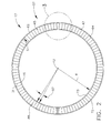
- FIG. 1 Illustrated in FIG. 1 is a portion of an exemplary turbofan gas turbine engine high pressure compressor 10 which is axisymmetrical about a longitudinal or axial centerline axis 12.
- Circular first and second rows 11, 13 of variable stator vanes 15 with non-uniform vane spacing (NUVS) are disposed in the compressor 10 and used to optimize the direction at which gases flowing downstream D through the compressor 10 enter first and second rows 17, 18 of rotatable blades 16.
- NUVS non-uniform vane spacing
- a compressor casing 61 radially outwardly supports variable stator vane assemblies 56 which include the variable stator vanes 15.
- the non-uniform variable stator vanes 15 illustrated herein have non-uniform airfoils 31.
- each variable stator vane assembly 56 includes a plurality of variable stator vanes 15. Each variable stator vane 15 is pivotable or rotatable about a rotational axis 20. Each variable stator vane 15 has an airfoil 31 disposed between spaced apart outer and inner buttons 32, 33. The airfoil 31 extends inwardly from an airfoil outer end 72 to an airfoil inner end 73 along a span S of the airfoil. The airfoil outer and inner ends 72, 73 are mounted on the outer and inner buttons 32, 33 respectively.
- An outer spindle 34 extends outwardly from the outer button 32 and an inner spindle 35 extends inwardly from the inner button 33.
- the outer and inner spindles 34, 35 are rotatably supported in outer and inner trunnions 36, 37 and centered and rotatable about the rotational axis 20.
- the outer spindle 34 is rotatably disposed through the outer trunnion 36 which, in turn, is mounted in an outer opening 78 in the casing 61.
- the outer openings 78 illustrated herein are equiangularly circumferentially spaced around the casing 61 at a constant radius about the axial centerline axis 12.
- the inner spindle 35 is rotatably disposed through the inner trunnion 37 which, in turn, is mounted in an inner opening 79 in an inner ring 81 which is spaced radially inwardly of the casing 61.
- a lever arm 80 extends from the outer spindle 34 and is linked to an actuation ring 82 for rotating or pivoting and setting the flow angle of the variable stator vanes 15.
- the outer and inner buttons 32, 33 are rotatably disposed in outer and inner circular recesses 42, 43 in the casing 61 and the inner ring 81 respectively.
- Each airfoil 31 has an airfoil leading edge LE upstream U of an airfoil trailing edges TE and pressure and suction sides PS, SS.
- the outer and inner buttons 32, 33 each have substantially circular edges 52 with a flat spot 53.
- Each of the circular edges 52 of outer and inner buttons 32, 33 define a circular perimeter 22 within which each button rotates about the rotational axis 20.
- the circular perimeter 22 is circumscribed about the rotational axis 20 at the button radius RB from the rotational axis 20.
- a recess 58 is cut out or recessed in from the perimeter 22.
- the recesses 58 are designed to maximize the area A of the button while accommodating a large turning angle (not shown) of the variable stator vanes 15.
- variable stator vane assembly 57 In order to reduce induced rotor blade vibration amplitudes, at least one of the variable stator vane assemblies 56 is a non-uniform variable stator vane assembly 57.
- the non-uniform variable stator vane assembly 57 includes different vanes in variable stator vane first and second or upper and lower sectors 62, 64 to facilitate avoidance of rotor blade and stator vane natural frequencies or to reduce the amplitude of rotor blade resonant response at these frequencies.
- the non-uniformity between the variable stator vanes 15 in the upper and lower sectors 62, 64 facilitates changing the frequency of the vane wakes to reduce the vibration response induced in adjacent rotor blades.
- the non-uniformity between the variable stator vanes 15 in the upper and lower sectors 62, 64 disclosed herein is different upper and lower leans of the airfoils 31 of the variable stator vanes 15 in the upper and lower sectors 62, 64 respectively.
- the airfoils 31 in one of the upper and lower sectors 62, 64 are leaned circumferentially more in the clockwise direction CW and airfoils 31 in another of the upper and lower sectors 62, 64 are leaned circumferentially more in the counter-clockwise direction CCW. All the airfoils 31 may still be leaned in either the clockwise or the counter-clockwise directions they are just biased more in one or the other circumferential directions.
- variable stator vanes 15 are substantially identical and uniform and, more particularly, uniformally circumferentially leaned.
- One embodiment of the number of sectors includes only one vane in each sector and each pair 28 of adjacent vanes has two different airfoil lean angles illustrated as clockwise and counter-clockwise airfoil lean angles 24, 26 as illustrated in FIG. 7 .
- One exemplary embodiment of the non-uniform variable stator vane assembly 57 illustrated herein includes different upper and lower airfoil lean angles 83, 84 of the airfoils 31 of the variable stator vanes 15 in the upper and lower sectors 62, 64 respectively as illustrated in FIG. 3 .
- the airfoils 31 of the variable stator vanes 15 in the upper and lower sectors 62, 64 are leaned in the counter-clockwise and clockwise directions CC, CCW at the upper and lower airfoil lean angles 83, 84 respectively as illustrated in FIG. 3 .
- the airfoils 31 in the upper and lower sectors 62, 64 are leaned in the counter-clockwise and clockwise directions CC, CCW with respect to a nominal airfoil lean angle 88 which may be 0 degrees or another angle.
- the lean angles may be about 17% of an acute angle 87 between the airfoil outer ends 72 of adjacent airfoils 31 as measured along engine radii R extending radially outwardly from the engine axial centerline axis 12 to the airfoil outer ends 72 on the outer buttons 32.
- the upper and lower airfoil lean angles 83, 84 of the airfoil 31 may be defined by upper and lower stacking axes illustrated by upper and lower stacking axes 85, 86 of the airfoils 31 in the upper and lower sectors 62, 64 respectively.
- a linear stacking axis may be described as a line connecting airfoil cross section center of gravities (CGs) at the airfoil outer and inner ends 72, 73 of an unleaned nominal airfoil 30 and counter-clockwise and clockwise shifted or leaned airfoils 45, 47 ( FIGS. 3-5 ) at the outer and inner buttons 32, 33 respectively of the vanes.
- Lean is a rotation of the airfoil 31 about the inner end 73 of the airfoil 31 causing the stacking axis to diverge from the engine radius R measured from the engine axial centerline axis 12.
- a bowed or arcuate stacking axis may be defined by the center of gravities of the several radial sections of each airfoil, or in any other conventional manner such as, by the stacking of the midchord points thereof.
- Stacking axis has also been defined as representing a locus of center of gravities of transverse sections of an airfoil portion of the blade and may be linear or non-linear.
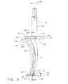
- FIGS. 4 and 5 Another means for providing non-uniformity between the variable stator vanes 15 in the upper and lower sectors 62, 64 is illustrated in FIGS. 4 and 5 .
- the means includes shifting the airfoil outer ends 72 from a nominal airfoil position 66 illustrated in dashed line to counter-clockwise and clockwise positions illustrated in solid line in the different sectors as illustrated in FIGS. 4 and 5 respectively.
- a nominal airfoil 31 is illustrated in dashed line counter in FIGS. 4 and 5 and counter-clockwise and clockwise shifted or leaned airfoils 45, 47 are illustrated in FIGS. 4 and 5 respectively.
- the inner ends 73 of the counter-clockwise and clockwise shifted or leaned airfoils 45, 47 remain the same as the inner end 73 of the nominal airfoil 31.
- Counter-clockwise and clockwise biased airfoils 45, 47 is a broader description of the non-uniformity.
- the nominal airfoil position 66 illustrated herein is between the counter-clockwise and clockwise biased airfoils 45, 47.
- variable stator vanes 15 in the upper sector 62 may be identical and all the variable stator vanes 15 in the lower sector 64 may be identical wherein the difference between the two sets of the variable stator vanes 15 is the counter-clockwise and clockwise biased airfoils 45,47.
- the shifting or leaning of the airfoils or other non-uniformity between the variable stator vanes 15 in the upper and lower sectors 62, 64 may thus be provided without changing the location size or shape of the outer and inner buttons 32, 33, the outer spindle and inner spindles 34, 35, the outer and inner trunnions 36, 37, and the outer openings 78 in the casing 61 illustrated in FIG. 6 .
- the span S of the airfoils defines a radial distance between the outer and inner buttons 32, 33 of the variable stator vanes 15 and may also all be the same.
- variable stator vanes 15 having cantilevered airfoils 90 cantilevered from and extending radially inwardly or downwardly from outer buttons 32 and having no inner buttons.
- Each cantilevered airfoil 90 extends inwardly from an airfoil outer end 72 to an airfoil inner end 73 along a span S of the airfoil and the inner end 73 is a free end.
- the airfoil outer end 72 is mounted on the outer button 32.
- An outer spindle 34 extends outwardly from the outer button 32.
- the outer spindle 34 is rotatably supported in an outer trunnion 36 and centered and rotatable about the rotational axis 20.
- the cantilevered airfoils 90 may be defined by upper and lower stacking axes illustrated by upper and lower stacking axes 85, 86 of the airfoils 31 in the upper and lower sectors 62, 64 respectively.
- a linear stacking axis may be described as a line connecting airfoil cross section center of gravities (CGs) at the airfoil outer and inner ends 72, 73 of an unleaned nominal cantilevered airfoil 90 and counter-clockwise and clockwise shifted or leaned cantilevered airfoils 92, 94 ( FIGS. 8-9 ).
- Lean is a rotation of the unleaned cantilevered airfoils 90 about the inner end 73 causing the stacking axis to diverge from the engine radius R measured from the engine axial centerline axis 12.
Landscapes
- Engineering & Computer Science (AREA)
- Mechanical Engineering (AREA)
- General Engineering & Computer Science (AREA)
- Physics & Mathematics (AREA)
- Fluid Mechanics (AREA)
- Geometry (AREA)
- Structures Of Non-Positive Displacement Pumps (AREA)
- Turbine Rotor Nozzle Sealing (AREA)
- Control Of Turbines (AREA)
Applications Claiming Priority (1)
| Application Number | Priority Date | Filing Date | Title |
|---|---|---|---|
| US13/271,617 US20130094942A1 (en) | 2011-10-12 | 2011-10-12 | Non-uniform variable vanes |
Publications (2)
| Publication Number | Publication Date |
|---|---|
| EP2581556A2 true EP2581556A2 (fr) | 2013-04-17 |
| EP2581556A3 EP2581556A3 (fr) | 2014-05-14 |
Family
ID=47080309
Family Applications (1)
| Application Number | Title | Priority Date | Filing Date |
|---|---|---|---|
| EP12188237.7A Withdrawn EP2581556A3 (fr) | 2011-10-12 | 2012-10-11 | Aubes variables avec inclinaison non uniforme |
Country Status (4)
| Country | Link |
|---|---|
| US (1) | US20130094942A1 (fr) |
| EP (1) | EP2581556A3 (fr) |
| JP (1) | JP2013083252A (fr) |
| CA (1) | CA2791971A1 (fr) |
Cited By (1)
| Publication number | Priority date | Publication date | Assignee | Title |
|---|---|---|---|---|
| US9683449B2 (en) | 2013-03-04 | 2017-06-20 | Rolls-Royce Plc | Stator vane row |
Families Citing this family (14)
| Publication number | Priority date | Publication date | Assignee | Title |
|---|---|---|---|---|
| ITTO20110728A1 (it) * | 2011-08-04 | 2013-02-05 | Avio Spa | Segmento palettato statorico di una turbina a gas per motori aeronautici |
| EP2653658A1 (fr) * | 2012-04-16 | 2013-10-23 | Siemens Aktiengesellschaft | Stator pour une turbomachine axiale et procédé de dimensionnement du stator |
| US9581034B2 (en) * | 2013-03-14 | 2017-02-28 | Elliott Company | Turbomachinery stationary vane arrangement for disk and blade excitation reduction and phase cancellation |
| EP3009604B1 (fr) * | 2014-09-19 | 2018-08-08 | United Technologies Corporation | Système d'aubes fixes-variables fixées radialement |
| FR3043650B1 (fr) * | 2015-11-16 | 2018-11-30 | Safran Aircraft Engines | Aube de stator de turbomachine, carter de soufflante comprenant une telle aube, systeme d'inversion de poussee d'une turbomachine equipee d'une telle aube et turbomachine equipee de ladite aube, dudit carter ou dudit systeme |
| US10443626B2 (en) | 2016-03-15 | 2019-10-15 | General Electric Company | Non uniform vane spacing |
| JP7017446B2 (ja) * | 2018-03-20 | 2022-02-08 | 本田技研工業株式会社 | 軸流圧縮機 |
| DE102018117884A1 (de) * | 2018-07-24 | 2020-01-30 | Rolls-Royce Deutschland Ltd & Co Kg | Strukturbaugruppe für einen Verdichter einer Strömungsmaschine |
| GB2574493A (en) * | 2019-01-22 | 2019-12-11 | Rolls Royce Plc | Stacking of rotor blade aerofoil sections to adjust resonant frequencies |
| FR3115321B1 (fr) * | 2020-10-20 | 2023-03-03 | Safran Aircraft Engines | étage de redressement d’un flux d’air pour une turbomachine |
| CN113623076B (zh) * | 2021-09-06 | 2022-07-22 | 中国联合重型燃气轮机技术有限公司 | 一种重型燃机进气缸 |
| US11713679B1 (en) * | 2022-01-27 | 2023-08-01 | Raytheon Technologies Corporation | Tangentially bowed airfoil |
| FR3133367B1 (fr) * | 2022-03-11 | 2024-08-23 | Safran Aircraft Engines | Propulseur aeronautique |
| US12366176B2 (en) * | 2023-08-28 | 2025-07-22 | General Electric Company | Rotor system for a turbine engine |
Family Cites Families (20)
| Publication number | Priority date | Publication date | Assignee | Title |
|---|---|---|---|---|
| US387793A (en) * | 1888-08-14 | Wall-paper-hanging machine | ||
| US360833A (en) * | 1887-04-05 | vogelsang | ||
| US3347520A (en) * | 1966-07-12 | 1967-10-17 | Jerzy A Oweczarek | Turbomachine blading |
| US3883264A (en) * | 1971-04-08 | 1975-05-13 | Gadicherla V R Rao | Quiet fan with non-radial elements |
| US4131387A (en) * | 1976-02-27 | 1978-12-26 | General Electric Company | Curved blade turbomachinery noise reduction |
| DE3801353C1 (fr) * | 1988-01-19 | 1989-03-23 | Rhein-Flugzeugbau Gmbh, 4050 Moenchengladbach, De | |
| US5088892A (en) * | 1990-02-07 | 1992-02-18 | United Technologies Corporation | Bowed airfoil for the compression section of a rotary machine |
| JPH11200808A (ja) * | 1998-01-07 | 1999-07-27 | Mitsubishi Heavy Ind Ltd | 圧縮機静翼 |
| US6439838B1 (en) * | 1999-12-18 | 2002-08-27 | General Electric Company | Periodic stator airfoils |
| FR2824597B1 (fr) * | 2001-05-11 | 2004-04-02 | Snecma Moteurs | Reduction de vibrations dans une structure comprenant un rotor et des sources de perturbation fixes |
| US7234914B2 (en) * | 2002-11-12 | 2007-06-26 | Continum Dynamics, Inc. | Apparatus and method for enhancing lift produced by an airfoil |
| US7125222B2 (en) * | 2004-04-14 | 2006-10-24 | General Electric Company | Gas turbine engine variable vane assembly |
| CA2574108C (fr) * | 2004-07-16 | 2016-05-24 | Bell Helicopter Textron Inc. | Dispositif anticouple pour helicoptere |
| DE102005011482B4 (de) * | 2005-03-12 | 2018-05-30 | Daimler Ag | Abgasturbolader mit einem Verdichter und einer Abgasturbine |
| US7743497B2 (en) * | 2005-10-06 | 2010-06-29 | General Electric Company | Method of providing non-uniform stator vane spacing in a compressor |
| US7594794B2 (en) * | 2006-08-24 | 2009-09-29 | United Technologies Corporation | Leaned high pressure compressor inlet guide vane |
| WO2010052911A1 (fr) * | 2008-11-05 | 2010-05-14 | 株式会社Ihi | Turbocompresseur |
| US8123471B2 (en) * | 2009-03-11 | 2012-02-28 | General Electric Company | Variable stator vane contoured button |
| US8834104B2 (en) * | 2010-06-25 | 2014-09-16 | Honeywell International Inc. | Vanes for directing exhaust to a turbine wheel |
| US8684685B2 (en) * | 2010-10-20 | 2014-04-01 | General Electric Company | Rotary machine having grooves for control of fluid dynamics |
-
2011
- 2011-10-12 US US13/271,617 patent/US20130094942A1/en not_active Abandoned
-
2012
- 2012-10-03 JP JP2012220934A patent/JP2013083252A/ja active Pending
- 2012-10-04 CA CA2791971A patent/CA2791971A1/fr not_active Abandoned
- 2012-10-11 EP EP12188237.7A patent/EP2581556A3/fr not_active Withdrawn
Non-Patent Citations (1)
| Title |
|---|
| None |
Cited By (1)
| Publication number | Priority date | Publication date | Assignee | Title |
|---|---|---|---|---|
| US9683449B2 (en) | 2013-03-04 | 2017-06-20 | Rolls-Royce Plc | Stator vane row |
Also Published As
| Publication number | Publication date |
|---|---|
| US20130094942A1 (en) | 2013-04-18 |
| CA2791971A1 (fr) | 2013-04-12 |
| JP2013083252A (ja) | 2013-05-09 |
| EP2581556A3 (fr) | 2014-05-14 |
Similar Documents
| Publication | Publication Date | Title |
|---|---|---|
| EP2581556A2 (fr) | Aubes variables avec inclinaison non uniforme | |
| US8123471B2 (en) | Variable stator vane contoured button | |
| US10443626B2 (en) | Non uniform vane spacing | |
| US10287902B2 (en) | Variable stator vane undercut button | |
| KR100984445B1 (ko) | 원심 압축기 | |
| EP3350452B1 (fr) | Hélice de machine à turbine de haute rigidité, machine à turbine comprenant ladite hélice et procédé de fabrication | |
| US7097420B2 (en) | Methods and apparatus for assembling gas turbine engines | |
| CN106894843B (zh) | 涡轮机及其涡轮叶片 | |
| CN106907188B (zh) | 涡轮机及其涡轮喷嘴 | |
| CN112983885B (zh) | 用于燃气涡轮发动机的风扇的分流器和转子翼型件的围带 | |
| JP6499636B2 (ja) | 異なる後縁プロフィルを持つベーンを交互に配置したベーン配置 | |
| US10584591B2 (en) | Rotor with subset of blades having a cutout leading edge | |
| EP2578805A1 (fr) | Pale de moteur à turbine à gaz avec creux à l'extrémité de pale | |
| WO2017105259A1 (fr) | Aube et turbomachine correspondante | |
| WO2017105260A1 (fr) | Aube et turbomachine correspondante | |
| EP3596311B1 (fr) | Pales carénées à résistance au flottement améliorée | |
| EP3596312B1 (fr) | Pales amorties ayant une résistance au flottement améliorée | |
| JP2023166117A (ja) | 可変静翼及び圧縮機 | |
| JP2020176598A (ja) | 軸流圧縮機 |
Legal Events
| Date | Code | Title | Description |
|---|---|---|---|
| PUAI | Public reference made under article 153(3) epc to a published international application that has entered the european phase |
Free format text: ORIGINAL CODE: 0009012 |
|
| AK | Designated contracting states |
Kind code of ref document: A2 Designated state(s): AL AT BE BG CH CY CZ DE DK EE ES FI FR GB GR HR HU IE IS IT LI LT LU LV MC MK MT NL NO PL PT RO RS SE SI SK SM TR |
|
| AX | Request for extension of the european patent |
Extension state: BA ME |
|
| PUAL | Search report despatched |
Free format text: ORIGINAL CODE: 0009013 |
|
| AK | Designated contracting states |
Kind code of ref document: A3 Designated state(s): AL AT BE BG CH CY CZ DE DK EE ES FI FR GB GR HR HU IE IS IT LI LT LU LV MC MK MT NL NO PL PT RO RS SE SI SK SM TR |
|
| AX | Request for extension of the european patent |
Extension state: BA ME |
|
| RIC1 | Information provided on ipc code assigned before grant |
Ipc: F01D 5/14 20060101AFI20140404BHEP Ipc: F01D 5/26 20060101ALI20140404BHEP |
|
| 17P | Request for examination filed |
Effective date: 20141114 |
|
| RBV | Designated contracting states (corrected) |
Designated state(s): AL AT BE BG CH CY CZ DE DK EE ES FI FR GB GR HR HU IE IS IT LI LT LU LV MC MK MT NL NO PL PT RO RS SE SI SK SM TR |
|
| STAA | Information on the status of an ep patent application or granted ep patent |
Free format text: STATUS: THE APPLICATION IS DEEMED TO BE WITHDRAWN |
|
| 18D | Application deemed to be withdrawn |
Effective date: 20170503 |