EP2581612A1 - Structure pour vis auto-perceuse - Google Patents
Structure pour vis auto-perceuse Download PDFInfo
- Publication number
- EP2581612A1 EP2581612A1 EP11185136.6A EP11185136A EP2581612A1 EP 2581612 A1 EP2581612 A1 EP 2581612A1 EP 11185136 A EP11185136 A EP 11185136A EP 2581612 A1 EP2581612 A1 EP 2581612A1
- Authority
- EP
- European Patent Office
- Prior art keywords
- cutting edge
- self
- sharp points
- tip section
- drilling screw
- Prior art date
- Legal status (The legal status is an assumption and is not a legal conclusion. Google has not performed a legal analysis and makes no representation as to the accuracy of the status listed.)
- Withdrawn
Links
- 238000005553 drilling Methods 0.000 title claims abstract description 46
- 238000007599 discharging Methods 0.000 claims abstract description 15
- 238000010079 rubber tapping Methods 0.000 description 7
- 238000000034 method Methods 0.000 description 3
- 229910000831 Steel Inorganic materials 0.000 description 1
- 238000012986 modification Methods 0.000 description 1
- 230000004048 modification Effects 0.000 description 1
- 239000010959 steel Substances 0.000 description 1
- 238000006467 substitution reaction Methods 0.000 description 1
Images


Classifications
-
- F—MECHANICAL ENGINEERING; LIGHTING; HEATING; WEAPONS; BLASTING
- F16—ENGINEERING ELEMENTS AND UNITS; GENERAL MEASURES FOR PRODUCING AND MAINTAINING EFFECTIVE FUNCTIONING OF MACHINES OR INSTALLATIONS; THERMAL INSULATION IN GENERAL
- F16B—DEVICES FOR FASTENING OR SECURING CONSTRUCTIONAL ELEMENTS OR MACHINE PARTS TOGETHER, e.g. NAILS, BOLTS, CIRCLIPS, CLAMPS, CLIPS OR WEDGES; JOINTS OR JOINTING
- F16B25/00—Screws that cut thread in the body into which they are screwed, e.g. wood screws
- F16B25/0036—Screws that cut thread in the body into which they are screwed, e.g. wood screws characterised by geometric details of the screw
- F16B25/0084—Screws that cut thread in the body into which they are screwed, e.g. wood screws characterised by geometric details of the screw characterised by geometric details of the tip
-
- F—MECHANICAL ENGINEERING; LIGHTING; HEATING; WEAPONS; BLASTING
- F16—ENGINEERING ELEMENTS AND UNITS; GENERAL MEASURES FOR PRODUCING AND MAINTAINING EFFECTIVE FUNCTIONING OF MACHINES OR INSTALLATIONS; THERMAL INSULATION IN GENERAL
- F16B—DEVICES FOR FASTENING OR SECURING CONSTRUCTIONAL ELEMENTS OR MACHINE PARTS TOGETHER, e.g. NAILS, BOLTS, CIRCLIPS, CLAMPS, CLIPS OR WEDGES; JOINTS OR JOINTING
- F16B25/00—Screws that cut thread in the body into which they are screwed, e.g. wood screws
- F16B25/001—Screws that cut thread in the body into which they are screwed, e.g. wood screws characterised by the material of the body into which the screw is screwed
- F16B25/0021—Screws that cut thread in the body into which they are screwed, e.g. wood screws characterised by the material of the body into which the screw is screwed the material being metal, e.g. sheet-metal or aluminium
-
- F—MECHANICAL ENGINEERING; LIGHTING; HEATING; WEAPONS; BLASTING
- F16—ENGINEERING ELEMENTS AND UNITS; GENERAL MEASURES FOR PRODUCING AND MAINTAINING EFFECTIVE FUNCTIONING OF MACHINES OR INSTALLATIONS; THERMAL INSULATION IN GENERAL
- F16B—DEVICES FOR FASTENING OR SECURING CONSTRUCTIONAL ELEMENTS OR MACHINE PARTS TOGETHER, e.g. NAILS, BOLTS, CIRCLIPS, CLAMPS, CLIPS OR WEDGES; JOINTS OR JOINTING
- F16B25/00—Screws that cut thread in the body into which they are screwed, e.g. wood screws
- F16B25/10—Screws performing an additional function to thread-forming, e.g. drill screws or self-piercing screws
- F16B25/103—Screws performing an additional function to thread-forming, e.g. drill screws or self-piercing screws by means of a drilling screw-point, i.e. with a cutting and material removing action
Definitions
- the present invention generally relates to a structure of self-drilling screw, and more particularly to a structure of self-drilling screw that avoids entangling of chips and raises tapping speed.
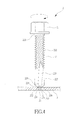
- a conventional self-drilling screw 1 as shown in FIG 1 , comprises a head 11 and a cylindrical body 12 mounted to the head 11.
- the body 12 has a circumferential surface 121 forming a helical thread 122.
- the body 12 has an end portion forming a chisel tip section 123.
- the chisel tip section 123 forms a conic surface 124 facing outward.
- two chip discharging channels 125 are formed in the chisel tip section 123, and each of the chip discharging channels 125 forms a cutting edge 126 at the connection thereof with each of the conic surface 124 and the circumferential surface 121 of the body 12.
- the cutting edges 126 are first applied to carry out drilling and chiseling in order to guide the self-drilling screw 1 forward for subsequent screwing.
- the chips generated during the drilling and chiseling process is guided by the chip discharging channels 125 to advance from the end of the chisel tip section 123 in an upward direction to be then discharged and thus achieving the function of screwing and positioning.
- the chip generated is in the form of a long strip that surrounds and entangles the thread 122, making it impossible to timely discharge the chip outward and, as a consequence, the tapping speed of the screw becomes unstable and impedes screwing in of the self-drilling screw 1.
- the screwing operation of the self-drilling screw 1 would consume an excessive time and may even get broken.
- the technical solution of the present invention is a structure of self-drilling screw, which comprises a head and a body mounted to the head.
- the body has a circumferential surface around which a helical thread is formed.
- the body has an end forming a cylindrical chisel tip section.
- the chisel tip section forms a conic surface facing outward.
- Two chip discharging channels are formed in the chisel tip section, and each of the chip discharging channels forms an external cutting edge at a connection thereof with the conic surface.
- the conic surface and the external cutting edges have a connection interface therebetween in which an inverted V-shaped notch is formed.
- the notch has two sides each forming an internal cutting edge.
- the inverted V-shaped notch forms two sharp points with respect to the external cutting edges, whereby the two sharp points are each associated with the respective external cutting edge and the respective internal cutting edge.
- Each of the sharp points forms an included angle.
- the two sharp points that are associated with the external cutting edges and the internal cutting edges can effectively cut off chips generated in a drilling and chiseling operation, so as to keep the chips from surrounding and entangling the thread and improve the tapping speed.
- each of the sharp points forms an included angle that ranges between 15°-135°.
- the two sharp points are spaced by a distance that is not greater than 25% of the outside diameter of the chisel tip section so that the self-drilling screw shows excellent performance of cutting and stability in a drilling and chiseling operation.
- the present invention provides a self-drilling screw 2, which comprises a head 21 and a body 22 mounted to the head 21.
- the body 22 has a circumferential surface 221 around which a helical thread 222 is formed.
- the body 22 has an end forming a cylindrical chisel tip section 223.
- the chisel tip section 223 forms a conic surface 224 facing outward.
- two chip discharging channels 225 are formed in the chisel tip section 223. Each of the chip discharging channels 225 forms an external cutting edge 226 at connection thereof with the conic surface 224.
- the conic surface 224 and the external cutting edges 226 have a connection interface therebetween in which an inverted V-shaped notch 23 is formed.
- the notch 23 has two sides each forming an internal cutting edge 231.
- the notch 23 also forms two sharp points 232 with respect to the external cutting edges 226, whereby the two sharp points 232 are each associated with the respective external cutting edge 226 and the respective internal cutting edge 231. Further, each of the sharp points 232 forms an included angle ⁇ .
- the included angle ⁇ is preferably between 15°-135° to facilitate drilling and chiseling operation of the sharp point 232.
- the two sharp points 232 are preferably spaced by a distance D that is not greater than 25% of outside diameter of the chisel tip section 223 in order to facilitate overall stability of the chisel tip section 223 during the drilling and chiseling operation.
- the self-drilling screw 2 is arranged in a vertical direction to allow the two sharp points 232 of the notch 23 to be positioned on a surface of a work piece 3 for subsequently chiseling and drilling into the work piece 3. Under this condition, the two sharp points 232 allow the self-drilling screw 2 to be properly and well positioned in performing drilling.
- the arrangement of the notch 23 and the chisel tip section 223 allows the force applied to be in a balanced condition and automatically corrects the drilling-in angle of the self-drilling screw 2.
- the screwing-in process into the work piece 3 When the notch 23 and the chisel tip section 223 of the self-drilling screw 2 contact and chisel the work piece 3, the screwing-in process into the work piece 3 generates chips and the chips, if being of a form of long strip, are cut off to small pieces by the internal cutting edge 231 and the external cutting edge 226 of each of the two sharp points 232 and are discharged through the chip discharging channels 225 thereby keeping the chips from surrounding and entangling the thread 222 and thus allowing the self-drilling screw 2 to fast screw into the work piece 3. As such, the self-drilling screw 2 can be tightened into the work piece 3 in a smooth manner and not impeded by the chips.
- the present invention has been tested according to DIN7504 standards and is proven to be effective in increasing drilling and tapping speed.
- the effectiveness of the present invention is that the arrangement of an inverted V-shaped notch 23 at the connection between the conic surface 224 and the external cutting edges 226 of the self-drilling screw 2 and the notch 23 has two sides each forming an internal cutting edge 231.
- the notch 23 forms two sharp points 232 with respect to the external cutting edges 226, whereby the two sharp points 232 are each associated with the respective external cutting edge 226 and the respective internal cutting edge 231.
- each of the sharp points 232 forms an included angle ⁇ .
- the included angle ⁇ of each of the sharp points 232 is between 15°-135°to facilitate drilling and chiseling operation of the sharp point 232.
- the two sharp points 232 are preferably spaced by a distance D that is not greater than 25% of outside diameter of the chisel tip section 223 in order to facilitate overall stability of the self-drilling screw 2 during the drilling and chiseling operation.
- the self-drilling screw 2 during the drilling and chiseling operation thereof, generates chips, which are cut to pieces by the internal cutting edge 231 and the external cutting edge 226 of each of the sharp points 232 to prevent excessively elongating the chips and causing the chips to surround and entangle the thread 222, thereby eliminating the potential risk of jamming of the thread 222 and breaking of the screw.
- the internal cutting edges 231 of the notch 23 also helpful in drilling and chiseling the work piece 3 and cutting off chips on the associated side so that all the chips are broken into pieces that are discharged through the chip discharging channels 225. As such, chip discharging of the self-drilling screw 2 is improved, screwing can be made stable, and tapping speed is improved.
- the structure of self-drilling screw according to the present invention is effectively in overcoming the shortcomings of the conventional self-drilling screw and may improve smoothness of discharging chips and increase tapping speed, making it highly valuable for the industry0.
Landscapes
- Engineering & Computer Science (AREA)
- General Engineering & Computer Science (AREA)
- Mechanical Engineering (AREA)
- Physics & Mathematics (AREA)
- Geometry (AREA)
- Drilling Tools (AREA)
Priority Applications (1)
| Application Number | Priority Date | Filing Date | Title |
|---|---|---|---|
| EP11185136.6A EP2581612A1 (fr) | 2011-10-14 | 2011-10-14 | Structure pour vis auto-perceuse |
Applications Claiming Priority (1)
| Application Number | Priority Date | Filing Date | Title |
|---|---|---|---|
| EP11185136.6A EP2581612A1 (fr) | 2011-10-14 | 2011-10-14 | Structure pour vis auto-perceuse |
Publications (1)
| Publication Number | Publication Date |
|---|---|
| EP2581612A1 true EP2581612A1 (fr) | 2013-04-17 |
Family
ID=44799827
Family Applications (1)
| Application Number | Title | Priority Date | Filing Date |
|---|---|---|---|
| EP11185136.6A Withdrawn EP2581612A1 (fr) | 2011-10-14 | 2011-10-14 | Structure pour vis auto-perceuse |
Country Status (1)
| Country | Link |
|---|---|
| EP (1) | EP2581612A1 (fr) |
Cited By (2)
| Publication number | Priority date | Publication date | Assignee | Title |
|---|---|---|---|---|
| EP4071371A1 (fr) * | 2021-01-07 | 2022-10-12 | Illinois Tool Works, Inc. | Élément de fixation autotaraudeur et autoperceur |
| AU2022200050B2 (en) * | 2021-01-07 | 2024-05-02 | Illinois Tool Works Inc. | Self-drilling self-tapping fastener |
Citations (3)
| Publication number | Priority date | Publication date | Assignee | Title |
|---|---|---|---|---|
| DE2738035A1 (de) * | 1976-08-24 | 1978-03-02 | Yamashina Seikosho Kk | Gewindeschneidschraube mit bohrspitze |
| GB2131726A (en) * | 1982-10-29 | 1984-06-27 | Nippon Oils & Fats Co Ltd | Drilling and end-milling tool |
| EP0468089A2 (fr) * | 1990-07-23 | 1992-01-29 | Kokubu Kagaku Kogyo Co., Ltd. | Vis autoperçante avec des arrêtes coupantes formant un arc curviligne vers la tête |
-
2011
- 2011-10-14 EP EP11185136.6A patent/EP2581612A1/fr not_active Withdrawn
Patent Citations (3)
| Publication number | Priority date | Publication date | Assignee | Title |
|---|---|---|---|---|
| DE2738035A1 (de) * | 1976-08-24 | 1978-03-02 | Yamashina Seikosho Kk | Gewindeschneidschraube mit bohrspitze |
| GB2131726A (en) * | 1982-10-29 | 1984-06-27 | Nippon Oils & Fats Co Ltd | Drilling and end-milling tool |
| EP0468089A2 (fr) * | 1990-07-23 | 1992-01-29 | Kokubu Kagaku Kogyo Co., Ltd. | Vis autoperçante avec des arrêtes coupantes formant un arc curviligne vers la tête |
Cited By (3)
| Publication number | Priority date | Publication date | Assignee | Title |
|---|---|---|---|---|
| EP4071371A1 (fr) * | 2021-01-07 | 2022-10-12 | Illinois Tool Works, Inc. | Élément de fixation autotaraudeur et autoperceur |
| AU2022200050B2 (en) * | 2021-01-07 | 2024-05-02 | Illinois Tool Works Inc. | Self-drilling self-tapping fastener |
| US12000421B2 (en) | 2021-01-07 | 2024-06-04 | Illinois Tool Works Inc. | Self-drilling self-tapping fastener |
Similar Documents
| Publication | Publication Date | Title |
|---|---|---|
| US8596943B2 (en) | Chipless thread-forming screw | |
| US10480561B2 (en) | Screw chip removal structure | |
| US20130336744A1 (en) | Threaded masonry fastener | |
| US20180156258A1 (en) | Structure of screw | |
| US20110229286A1 (en) | Versatile fastener | |
| AU2007101166A4 (en) | Multiple spur multiple spiral groove twist drill | |
| EP2580486B1 (fr) | Vis comportant deux bords sur le filetage | |
| JP2016121797A (ja) | 打ち込み式ねじ釘 | |
| US8632289B2 (en) | Tapping screw | |
| EP3354913A1 (fr) | Structure pour vis auto-perceuse | |
| US20170016467A1 (en) | Wooden screw | |
| EP2581612A1 (fr) | Structure pour vis auto-perceuse | |
| US20130089390A1 (en) | Structure of self-drilling screw | |
| CA2754925A1 (fr) | Structure d'une vis autotaraudeuse | |
| TWI598516B (zh) | 固定方法 | |
| US20160208842A1 (en) | Screw | |
| AU2013207133B2 (en) | Fasteners | |
| US10690173B2 (en) | Structure of screw | |
| EP2339189A1 (fr) | Vis | |
| RU163414U1 (ru) | Устройство для соединения транспортерных лент | |
| US20190162221A1 (en) | Quick drilling screw | |
| JP2015007475A (ja) | 施工性に優れたドリルねじ及びスチール構造枠 | |
| JP2012107699A (ja) | ねじ | |
| KR20160020143A (ko) | 셀프 태핑 나사 | |
| EP1803945A3 (fr) | Vis à bois |
Legal Events
| Date | Code | Title | Description |
|---|---|---|---|
| PUAI | Public reference made under article 153(3) epc to a published international application that has entered the european phase |
Free format text: ORIGINAL CODE: 0009012 |
|
| AK | Designated contracting states |
Kind code of ref document: A1 Designated state(s): AL AT BE BG CH CY CZ DE DK EE ES FI FR GB GR HR HU IE IS IT LI LT LU LV MC MK MT NL NO PL PT RO RS SE SI SK SM TR |
|
| AX | Request for extension of the european patent |
Extension state: BA ME |
|
| STAA | Information on the status of an ep patent application or granted ep patent |
Free format text: STATUS: THE APPLICATION IS DEEMED TO BE WITHDRAWN |
|
| 18D | Application deemed to be withdrawn |
Effective date: 20131018 |