EP2581621A1 - Verfahren zur herstellung von bremsscheiben und bremsscheibe - Google Patents
Verfahren zur herstellung von bremsscheiben und bremsscheibe Download PDFInfo
- Publication number
- EP2581621A1 EP2581621A1 EP11792070.2A EP11792070A EP2581621A1 EP 2581621 A1 EP2581621 A1 EP 2581621A1 EP 11792070 A EP11792070 A EP 11792070A EP 2581621 A1 EP2581621 A1 EP 2581621A1
- Authority
- EP
- European Patent Office
- Prior art keywords
- main body
- outer peripheral
- disc main
- plate thickness
- blanking
- Prior art date
- Legal status (The legal status is an assumption and is not a legal conclusion. Google has not performed a legal analysis and makes no representation as to the accuracy of the status listed.)
- Withdrawn
Links
Images

Classifications
-
- F—MECHANICAL ENGINEERING; LIGHTING; HEATING; WEAPONS; BLASTING
- F16—ENGINEERING ELEMENTS AND UNITS; GENERAL MEASURES FOR PRODUCING AND MAINTAINING EFFECTIVE FUNCTIONING OF MACHINES OR INSTALLATIONS; THERMAL INSULATION IN GENERAL
- F16D—COUPLINGS FOR TRANSMITTING ROTATION; CLUTCHES; BRAKES
- F16D65/00—Parts or details
- F16D65/02—Braking members; Mounting thereof
- F16D65/12—Discs; Drums for disc brakes
-
- B—PERFORMING OPERATIONS; TRANSPORTING
- B21—MECHANICAL METAL-WORKING WITHOUT ESSENTIALLY REMOVING MATERIAL; PUNCHING METAL
- B21D—WORKING OR PROCESSING OF SHEET METAL OR METAL TUBES, RODS OR PROFILES WITHOUT ESSENTIALLY REMOVING MATERIAL; PUNCHING METAL
- B21D53/00—Making other particular articles
- B21D53/26—Making other particular articles wheels or the like
- B21D53/34—Making other particular articles wheels or the like brake drums
-
- F—MECHANICAL ENGINEERING; LIGHTING; HEATING; WEAPONS; BLASTING
- F16—ENGINEERING ELEMENTS AND UNITS; GENERAL MEASURES FOR PRODUCING AND MAINTAINING EFFECTIVE FUNCTIONING OF MACHINES OR INSTALLATIONS; THERMAL INSULATION IN GENERAL
- F16D—COUPLINGS FOR TRANSMITTING ROTATION; CLUTCHES; BRAKES
- F16D65/00—Parts or details
- F16D65/02—Braking members; Mounting thereof
- F16D2065/026—Braking members; Mounting thereof characterised by a particular outline shape of the braking member, e.g. footprint of friction lining
-
- F—MECHANICAL ENGINEERING; LIGHTING; HEATING; WEAPONS; BLASTING
- F16—ENGINEERING ELEMENTS AND UNITS; GENERAL MEASURES FOR PRODUCING AND MAINTAINING EFFECTIVE FUNCTIONING OF MACHINES OR INSTALLATIONS; THERMAL INSULATION IN GENERAL
- F16D—COUPLINGS FOR TRANSMITTING ROTATION; CLUTCHES; BRAKES
- F16D69/00—Friction linings; Attachment thereof; Selection of coacting friction substances or surfaces
- F16D2069/004—Profiled friction surfaces, e.g. grooves, dimples
-
- F—MECHANICAL ENGINEERING; LIGHTING; HEATING; WEAPONS; BLASTING
- F16—ENGINEERING ELEMENTS AND UNITS; GENERAL MEASURES FOR PRODUCING AND MAINTAINING EFFECTIVE FUNCTIONING OF MACHINES OR INSTALLATIONS; THERMAL INSULATION IN GENERAL
- F16D—COUPLINGS FOR TRANSMITTING ROTATION; CLUTCHES; BRAKES
- F16D2250/00—Manufacturing; Assembly
-
- F—MECHANICAL ENGINEERING; LIGHTING; HEATING; WEAPONS; BLASTING
- F16—ENGINEERING ELEMENTS AND UNITS; GENERAL MEASURES FOR PRODUCING AND MAINTAINING EFFECTIVE FUNCTIONING OF MACHINES OR INSTALLATIONS; THERMAL INSULATION IN GENERAL
- F16D—COUPLINGS FOR TRANSMITTING ROTATION; CLUTCHES; BRAKES
- F16D2250/00—Manufacturing; Assembly
- F16D2250/0092—Tools or machines for producing linings
-
- Y—GENERAL TAGGING OF NEW TECHNOLOGICAL DEVELOPMENTS; GENERAL TAGGING OF CROSS-SECTIONAL TECHNOLOGIES SPANNING OVER SEVERAL SECTIONS OF THE IPC; TECHNICAL SUBJECTS COVERED BY FORMER USPC CROSS-REFERENCE ART COLLECTIONS [XRACs] AND DIGESTS
- Y10—TECHNICAL SUBJECTS COVERED BY FORMER USPC
- Y10T—TECHNICAL SUBJECTS COVERED BY FORMER US CLASSIFICATION
- Y10T29/00—Metal working
- Y10T29/49—Method of mechanical manufacture
- Y10T29/49995—Shaping one-piece blank by removing material
Definitions
- the present invention relates to a method of manufacturing a brake disc having an outer peripheral shape of projections-recesses repetition in which a radial projection and a radial recess are alternately repeated in the circumferential direction of the brake disc, and relates to a brake disc.
- Patent Document 1 a method in which a disc main body having an outer peripheral shape of projections-recesses repetition is blanked (stamped) by a single pressing from one of plate thickness directions of a sheet material.
- a chamfering mold is forced against the outer peripheral edge portion of the disc main body, after blanking, so as to crush the burrs, thereby forming a chamfered surface.
- the disc main body is blanked by a single pressing work in one of plate thickness directions of a sheet material, the area in a broken-out (ruptured) portion at the outer peripheral surface of the disc main body becomes large, thereby making the obtained product unfit for use as a brake disc whose aesthetic impression is important. Therefore, in order to remove the broken-out portion, a step of cutting the outer periphery of the disc main body will become essential.
- Patent Document 1 JP-A-2008-232441
- this invention has a problem of providing a method of manufacturing a brake disc, and a brake disc, in which curved face portions can be formed uniformly in the outer peripheral edge portion over the entire outer circumference of the disc main body, and in which a chamfering process to remove burrs or an outer periphery cutting process is eliminated, resulting in superiority in productivity.
- the first invention of this application is a method of manufacturing a brake disc having an outer peripheral shape of projections-recesses repetition in which a radial projection and a radial recess are alternately repeated in a circumferential direction of the brake disc.
- the method comprises: a half-blanking step of half-blanking a disc main body having the outer peripheral shape of projections-recesses repetition, the half-blanking being performed from one of plate thickness directions of a sheet material; and a blanking step of blanking the disc main body from the other of the plate thickness directions of the sheet material.
- the second invention of this application is a brake disc having an outer peripheral shape of projections-recesses repetition in which a radial projection and a radial recess are alternately repeated in a circumferential direction of the brake disc.
- a disc main body having the outer peripheral shape of projections-recesses repetition is half-blanked from one of plate thickness directions of a sheet material, and the disc main body is blanked from the other of the plate thickness directions of the sheet material such that a curved face portion is formed on the disc main body at an outer peripheral edge portion of each surface in said one and the other of the plate thickness directions of the sheet material.
- Each of the curved face portions is in continuation of a sheared portion on an outer peripheral surface of the disc main body.
- the curved face portion is in continuation of that sheared portion, to be formed by blanking, which is generated on the outer peripheral surface of the disc main body. Therefore, like the above-mentioned second invention, there will be formed a curved face portion on the disc main body at an outer peripheral edge portion of each surface in said one and the other of the plate thickness directions of the sheet material.
- Each of the curved face portions is in continuation of sheared portions on an outer peripheral surface of the disc main body.
- these curved face portions are formed by sagging which come into existence as a result of half-blanking and blanking, they are different from those in which chamfered surfaces are formed by embossing with chamfering mold. Even if there are fluctuations in thicknesses of sheet materials, the curved face portions can be formed uniformly over the entire circumference of the disc main body, thereby improving the aesthetic impression.
- this half-blanking mold which serves as a replacement for the chamfering mold in the above-mentioned conventional example.
- this half-blanking mold is not subject to local heavy loads. As a result, frequent replacement becomes unnecessary, with a consequent improvement in productivity.
- the inner diameter of the die to be used in the half-blanking step smaller than the outer diameter of the punch. According to this configuration, the disc main body to be half-blanked will be forced under pressure into the die. Therefore, the sheared portion of the outer peripheral surface of the disc main body is formed into a mirror-finished state, thereby improving the aesthetic impression.
- FIG. 1 shows a brake disc according to an embodiment of this invention.
- a shaft hole 2 for inserting thereinto a shaft (not illustrated) of a vehicle such as a motorcycle and the like.
- a plurality of fixing holes 3 are formed at an equal distance from one another in the circumferential direction, the fixing holes 3 being for fixing the disc main body 1 to a wheel hub on the shaft.
- a multiplicity of drain holes 4 are formed in that portion of the disc main body 1 which comes into sliding contact with a brake pad (not illustrated).
- the outer peripheral shape of the disc main body 1 is formed into a shape of projections-recesses repetition in which a radially recessed portion 5 and a radially projected portion 6 are alternately repeated in the circumferential direction of the disc main body 1.
- the numbers of the recessed portions 5 and the projected portions 6 are respectively 6. However, these numbers may be below 6 or above 6.
- the disc main body 1 whose outer peripheral shape is of projections-recesses repetition (see FIG. 2 ) is manufactured. Then, the disc main body 1 is subjected to the machining work of piercing the drain holes 4 and the shaft hole 2 in succession. Then, the disc main body 1 is sequentially subjected to the processing of quenching of the disc main body 1, boring by machining of the fixing holes 3, surface treatment, grinding of each surface, as seen in a thickness direction thereof, of the disc main body 1, and the like.
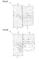
- the manufacturing of the disc main body 1 having an outer peripheral shape of projections-recesses repetition is performed in two steps of half-blanking step and blanking step. Detailed description will hereinafter be made of the half-blanking step and the blanking step with reference to FIG. 2 (a) and FIG. 2(b) .
- a mold 10 to be used in the half-blanking step is made up, as shown in FIG. 2(a) , of: a lower die 11 whose inner peripheral shape is formed into projections-recesses repetition; an upper punch 12 whose outer peripheral shape is formed into projections-recesses repetition; a blank holder 13 for pushing the outer peripheral portion of a sheet material W made of metal such as stainless steel and the like onto an upper surface of the die 11; and a pad 14 which is disposed inside the die 11 so as to lie opposite to the punch 12.
- the inner diameter R 11 of the die 11 (the inner diameters of the recessed portions and of the projected portions, respectively, of the die 11) is configured to be slightly smaller than the outer diameter R 12 of the punch 12 (the outer diameters of the recessed portions and of the projected portions, respectively, of the punch 12).
- the punch 12 is lowered in a state in which a surface in one of plate thickness directions of the sheet material W faces upward.
- the disc main body 1 having the outer peripheral shape of projections-recesses repetition is half-blanked from one of the plate thickness directions of the sheet material W by about 25 - 50% of the plate thickness.
- a sheared portion 1a is formed on the side of the other of the plate thickness directions along an outer peripheral surface of the disc main body 1, and there is further formed a curved face portion 1b at an outer peripheral edge portion of the surface in the other of the plate thickness directions of the disc main body 1, the curved face portion being generated by sagging in a manner to be in continuation of the sheared portion 1a.
- the disc main body 1 to be half-blanked will be press-fitted by force into the die 11. Therefore, the sheared portion 1a along the outer peripheral surface of the disc main body 1 will be formed into a mirror-finished state.
- the sheet material W is set in position onto a mold 20 to be used in blanking, as shown in FIG. 2(b) , in a state in which the sheet material W is placed upside down.
- This mold 20 is made up of: a lower die 21 whose inner peripheral shape is formed into projections-recesses repetition; an upper punch 22 whose outer peripheral shape is formed into projections-recesses repetition; and a blank holder 23 which presses the outer peripheral portion of the sheet material W against the upper surface of the die 21.
- the inner diameter R 21 of the die 21 is configured to be slightly larger than the outer diameter R 12 of the punch 12 of the half-blanking mold 10 and the outer diameter R 22 of the punch 22 is configured to be slightly smaller than the inner diameter R 11 of the die 11 of the half-blanking mold 10.
- the punch 22 is lowered in a state in which a surface in the other of the plate thickness directions of the sheet material W looks upward.
- the half-blanked disc main body 1 is thus blanked, as shown in imaginary lines in FIG. 2(b) , from the other of the plate thickness directions of the sheet material W.
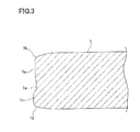
- shearing of the disc main body 1 will start with a bottom hole corner Wb of the recessed hole Wa, formed in the half-blanking, serving as an origin. Then, as shown in FIG. 3 , a sheared portion 1c due to blanking is formed in one side of the plate thickness directions along the outer peripheral surface of the disc main body 1. Along the outer peripheral edge portion of a surface in one of plate thickness directions of the disc main body 1, there is formed, as shown in FIG. 3 , a curved face portion 1d, due to sagging, which is in continuation of the sheared portion 1c.
- a broken-out (ruptured) portion 1e which is generated by blanking.
- This broken-out portion 1e becomes smaller in diameter than the sheared portions 1a, 1c. Therefore, safety can be secured because there is no possibility that the broken-out portion 1e protrudes beyond the outer peripheral surface of the disc main body 1.
- the broken-out portion 1e becomes smaller in area, thereby becoming less conspicuous to the eye, as compared with the conventional example in which the disc main body is blanked by a single pressing work from one of plate thickness directions.
- the reason why the outer diameter R 22 of the punch 22 of the blanking mold 20 is configured to be smaller than the inner diameter R 11 of the die 11 of the half-blanking mold 10 is to prevent the curved face portion 1b of the half-blanked disc main body 1 from getting out of shape, and also to prevent the burrs from being generated due to shearing once again of scrap by the punch 22.
- the reason why the inner diameter R 21 of the die 21 for the blanking mold 20 is configured to be larger than the outer diameter R 12 of the punch 12 of the half-blanking mold 10 is to prevent the disc main body 1 from getting sheared directly with the cutting tooth (corner portion) of the die 21 and to eliminate the possibility of chipping (breaking) at the corner portion of the die 21, thereby improving the durability of the die 21.
- the corner portion of the die 21 may be rounded in shape; the accuracy of the die 21 does not need to be made higher.
- a curved face portion 1b, 1d at an outer peripheral edge portion of the surface in each of the one and the other of the plate thickness directions of the disc main body 1, the curved face portions being in continuation of the sheared portions 1a, 1c on the outer peripheral surface of the disc main body 1.
- curved face portions 1b, 1d are formed by sagging to be generated by half-blanking and blanking, curved face portions 1b, 1d are uniformly formed over the entire circumference of the disc main body even though the plate thicknesses fluctuate. This feature is different from that of the case in which a chamfered surface is formed by embossing with a chamfering mold. As a result of combined effect in that the sheared portion 1a is formed into a mirror-finished surface, the aesthetic impression of the disc main body is improved.
- this invention was applied to a brake disc of a single-plate construction.
- this invention can also be applied to a floating type brake disc in which an annular rotor portion which comes into sliding contact with a brake pad and a hub portion which is fixed to a wheel hub are connected together in a floatable manner.
- this invention can be applied in a similar manner.
Landscapes
- Engineering & Computer Science (AREA)
- Mechanical Engineering (AREA)
- General Engineering & Computer Science (AREA)
- Braking Arrangements (AREA)
- Punching Or Piercing (AREA)
Applications Claiming Priority (2)
| Application Number | Priority Date | Filing Date | Title |
|---|---|---|---|
| JP2010132367A JP2011256949A (ja) | 2010-06-09 | 2010-06-09 | ブレーキディスクの製造方法及びブレーキディスク |
| PCT/JP2011/001552 WO2011155107A1 (ja) | 2010-06-09 | 2011-03-16 | ブレーキディスクの製造方法及びブレーキディスク |
Publications (2)
| Publication Number | Publication Date |
|---|---|
| EP2581621A1 true EP2581621A1 (de) | 2013-04-17 |
| EP2581621A4 EP2581621A4 (de) | 2018-03-07 |
Family
ID=45097729
Family Applications (1)
| Application Number | Title | Priority Date | Filing Date |
|---|---|---|---|
| EP11792070.2A Withdrawn EP2581621A4 (de) | 2010-06-09 | 2011-03-16 | Verfahren zur herstellung von bremsscheiben und bremsscheibe |
Country Status (5)
| Country | Link |
|---|---|
| US (1) | US20130025985A1 (de) |
| EP (1) | EP2581621A4 (de) |
| JP (1) | JP2011256949A (de) |
| BR (1) | BR112012031393A2 (de) |
| WO (1) | WO2011155107A1 (de) |
Cited By (1)
| Publication number | Priority date | Publication date | Assignee | Title |
|---|---|---|---|---|
| CN110405103A (zh) * | 2019-08-05 | 2019-11-05 | 浙江凌宇机械股份有限公司 | 一种刹车盘生产线 |
Families Citing this family (4)
| Publication number | Priority date | Publication date | Assignee | Title |
|---|---|---|---|---|
| CN102615181B (zh) * | 2012-02-27 | 2014-04-09 | 昆山三景科技股份有限公司 | 适用于冲制汽车刹车片的连续冲压模具及冲压方法 |
| CN103212620B (zh) * | 2012-05-18 | 2015-12-16 | 孙昌清 | 无毛刺冲裁方法和冲裁系统 |
| US10626935B2 (en) * | 2016-04-13 | 2020-04-21 | Sram, Llc | Brake rotor |
| JP6761319B2 (ja) * | 2016-10-05 | 2020-09-23 | 株式会社三井ハイテック | 鉄心片の製造方法 |
Family Cites Families (12)
| Publication number | Priority date | Publication date | Assignee | Title |
|---|---|---|---|---|
| DE2727445C2 (de) * | 1977-06-18 | 1979-09-06 | Lange, Kurt, Prof. Dr.-Ing., 7000 Stuttgart | Verfahren und Vorrichtung zum Ausschneiden und/oder Lochen von Werkstücken aus metallischen Flachwerkstoffen |
| US4477537A (en) * | 1982-09-23 | 1984-10-16 | Blase Tool And Manufacturing Co., Inc. | Method for producing burr-free blanks and the blanks produced thereby |
| JPS61189832A (ja) * | 1985-02-18 | 1986-08-23 | Hitachi Ltd | 上下抜き金型 |
| JPH06114595A (ja) * | 1992-10-05 | 1994-04-26 | Omron Corp | プレス装置のストローク制御装置 |
| JP2000210732A (ja) * | 1999-01-22 | 2000-08-02 | Nikkyo Corp | プレス打ち抜き製品のバリなし加工方法 |
| JP2001300647A (ja) * | 2000-04-24 | 2001-10-30 | Sankyo Seiki Mfg Co Ltd | プレス加工部品の製造方法、及びモータ用積層コアの製造方法 |
| JP2002066653A (ja) * | 2000-08-30 | 2002-03-05 | Sanyo Seisakusho:Kk | 金属板のプレス加工方法又は金属板のプレス加工装置 |
| JP2004167547A (ja) * | 2002-11-20 | 2004-06-17 | Nakamura Mfg Co Ltd | 薄板の剪断加工方法 |
| JP4315672B2 (ja) * | 2002-11-28 | 2009-08-19 | 株式会社三井ハイテック | 無段変速機用ベルトのエレメントの製造方法 |
| JP2004357349A (ja) * | 2003-05-27 | 2004-12-16 | Nakamura Mfg Co Ltd | 鉄心片の製造方法 |
| DE602004021732D1 (de) * | 2003-12-02 | 2009-08-06 | Sunstar Engineering Inc | |
| DE102007047836A1 (de) * | 2007-11-21 | 2009-05-28 | Zf Friedrichshafen Ag | Verfahren zum Herstellen einer gratfreien Schnittfläche und Vorrichtung zur Durchführung des Verfahrens |
-
2010
- 2010-06-09 JP JP2010132367A patent/JP2011256949A/ja active Pending
-
2011
- 2011-03-16 US US13/641,287 patent/US20130025985A1/en not_active Abandoned
- 2011-03-16 EP EP11792070.2A patent/EP2581621A4/de not_active Withdrawn
- 2011-03-16 BR BR112012031393A patent/BR112012031393A2/pt not_active Application Discontinuation
- 2011-03-16 WO PCT/JP2011/001552 patent/WO2011155107A1/ja not_active Ceased
Non-Patent Citations (1)
| Title |
|---|
| See references of WO2011155107A1 * |
Cited By (1)
| Publication number | Priority date | Publication date | Assignee | Title |
|---|---|---|---|---|
| CN110405103A (zh) * | 2019-08-05 | 2019-11-05 | 浙江凌宇机械股份有限公司 | 一种刹车盘生产线 |
Also Published As
| Publication number | Publication date |
|---|---|
| US20130025985A1 (en) | 2013-01-31 |
| WO2011155107A1 (ja) | 2011-12-15 |
| JP2011256949A (ja) | 2011-12-22 |
| EP2581621A4 (de) | 2018-03-07 |
| BR112012031393A2 (pt) | 2016-11-16 |
Similar Documents
| Publication | Publication Date | Title |
|---|---|---|
| CN111734743B (zh) | 轴承保持架 | |
| JP3526323B2 (ja) | ハブユニット軸受外輪の製造方法 | |
| EP2581621A1 (de) | Verfahren zur herstellung von bremsscheiben und bremsscheibe | |
| JP3676192B2 (ja) | 無段変速機用ベルトのエレメントの打抜き加工方法 | |
| JPWO2006080356A1 (ja) | プレス加工装置、プレス加工方法、及び打抜き加工品 | |
| KR20180131445A (ko) | 스탬핑된 부품을 제조하기 위한 방법 | |
| CN100368142C (zh) | 由轧制金属板制成的液压活塞和它的制造方法 | |
| JP2008229710A (ja) | プレス打ち抜き工法 | |
| JP4526739B2 (ja) | 円錐ころ軸受用保持器の製造方法 | |
| JPWO2015190580A1 (ja) | 軸受装置及び軸受装置の製造方法 | |
| JP4483365B2 (ja) | スラスト円筒ころ軸受用保持器とその製造方法 | |
| JP5224747B2 (ja) | せん断加工方法 | |
| JP2006263768A (ja) | プレス加工装置、及びプレス加工方法 | |
| JP2006142363A (ja) | ブレーキディスクの製造方法 | |
| JP3546364B2 (ja) | ハブユニット軸受外輪のセレーション孔加工方法 | |
| CN101102858A (zh) | 用于对离合器盘和最终产品进行冲压和去毛刺的装置和方法 | |
| JP3942256B2 (ja) | 軸受外輪及びその製造方法、並びにクラッチレリーズ軸受 | |
| JP2829270B2 (ja) | 板状製品のプレス自動製造方法 | |
| JP6063736B2 (ja) | ブレーキディスクの製造方法 | |
| EP3854499B1 (de) | Gestapelte anordnung und verfahren zur herstellung davon | |
| JPH05138260A (ja) | プレス機械の低騒音打抜き方法および装置 | |
| JPH07136721A (ja) | キャリヤの製造方法 | |
| JP2000079418A (ja) | 開口を有するクラッチカバーの成形方法 | |
| JP4999675B2 (ja) | 機械部品及びその製造方法 | |
| JP5084491B2 (ja) | 平板からの両面突出円筒部成形方法、及び両面突出円筒部一体成形品 |
Legal Events
| Date | Code | Title | Description |
|---|---|---|---|
| PUAI | Public reference made under article 153(3) epc to a published international application that has entered the european phase |
Free format text: ORIGINAL CODE: 0009012 |
|
| 17P | Request for examination filed |
Effective date: 20130108 |
|
| AK | Designated contracting states |
Kind code of ref document: A1 Designated state(s): AL AT BE BG CH CY CZ DE DK EE ES FI FR GB GR HR HU IE IS IT LI LT LU LV MC MK MT NL NO PL PT RO RS SE SI SK SM TR |
|
| DAX | Request for extension of the european patent (deleted) | ||
| RA4 | Supplementary search report drawn up and despatched (corrected) |
Effective date: 20180207 |
|
| RIC1 | Information provided on ipc code assigned before grant |
Ipc: B21D 53/88 20060101ALI20180201BHEP Ipc: F16D 65/12 20060101AFI20180201BHEP |
|
| STAA | Information on the status of an ep patent application or granted ep patent |
Free format text: STATUS: THE APPLICATION IS DEEMED TO BE WITHDRAWN |
|
| 18D | Application deemed to be withdrawn |
Effective date: 20180906 |