EP2581686A2 - Collecteur solaire - Google Patents
Collecteur solaire Download PDFInfo
- Publication number
- EP2581686A2 EP2581686A2 EP12186749.3A EP12186749A EP2581686A2 EP 2581686 A2 EP2581686 A2 EP 2581686A2 EP 12186749 A EP12186749 A EP 12186749A EP 2581686 A2 EP2581686 A2 EP 2581686A2
- Authority
- EP
- European Patent Office
- Prior art keywords
- absorber
- solar collector
- cover
- cavity
- collector according
- Prior art date
- Legal status (The legal status is an assumption and is not a legal conclusion. Google has not performed a legal analysis and makes no representation as to the accuracy of the status listed.)
- Withdrawn
Links
Images
Classifications
-
- F—MECHANICAL ENGINEERING; LIGHTING; HEATING; WEAPONS; BLASTING
- F24—HEATING; RANGES; VENTILATING
- F24S—SOLAR HEAT COLLECTORS; SOLAR HEAT SYSTEMS
- F24S10/00—Solar heat collectors using working fluids
- F24S10/70—Solar heat collectors using working fluids the working fluids being conveyed through tubular absorbing conduits
-
- F—MECHANICAL ENGINEERING; LIGHTING; HEATING; WEAPONS; BLASTING
- F24—HEATING; RANGES; VENTILATING
- F24S—SOLAR HEAT COLLECTORS; SOLAR HEAT SYSTEMS
- F24S40/00—Safety or protection arrangements of solar heat collectors; Preventing malfunction of solar heat collectors
- F24S40/10—Protective covers or shrouds; Closure members, e.g. lids
-
- F—MECHANICAL ENGINEERING; LIGHTING; HEATING; WEAPONS; BLASTING
- F24—HEATING; RANGES; VENTILATING
- F24S—SOLAR HEAT COLLECTORS; SOLAR HEAT SYSTEMS
- F24S40/00—Safety or protection arrangements of solar heat collectors; Preventing malfunction of solar heat collectors
- F24S40/80—Accommodating differential expansion of solar collector elements
-
- F—MECHANICAL ENGINEERING; LIGHTING; HEATING; WEAPONS; BLASTING
- F24—HEATING; RANGES; VENTILATING
- F24S—SOLAR HEAT COLLECTORS; SOLAR HEAT SYSTEMS
- F24S80/00—Details, accessories or component parts of solar heat collectors not provided for in groups F24S10/00-F24S70/00
- F24S80/40—Casings
-
- F—MECHANICAL ENGINEERING; LIGHTING; HEATING; WEAPONS; BLASTING
- F24—HEATING; RANGES; VENTILATING
- F24S—SOLAR HEAT COLLECTORS; SOLAR HEAT SYSTEMS
- F24S80/00—Details, accessories or component parts of solar heat collectors not provided for in groups F24S10/00-F24S70/00
- F24S80/50—Elements for transmitting incoming solar rays and preventing outgoing heat radiation; Transparent coverings
- F24S80/54—Elements for transmitting incoming solar rays and preventing outgoing heat radiation; Transparent coverings using evacuated elements
-
- F—MECHANICAL ENGINEERING; LIGHTING; HEATING; WEAPONS; BLASTING
- F24—HEATING; RANGES; VENTILATING
- F24S—SOLAR HEAT COLLECTORS; SOLAR HEAT SYSTEMS
- F24S80/00—Details, accessories or component parts of solar heat collectors not provided for in groups F24S10/00-F24S70/00
- F24S80/70—Sealing means
-
- F—MECHANICAL ENGINEERING; LIGHTING; HEATING; WEAPONS; BLASTING
- F24—HEATING; RANGES; VENTILATING
- F24S—SOLAR HEAT COLLECTORS; SOLAR HEAT SYSTEMS
- F24S25/00—Arrangement of stationary mountings or supports for solar heat collector modules
- F24S25/60—Fixation means, e.g. fasteners, specially adapted for supporting solar heat collector modules
- F24S2025/601—Fixation means, e.g. fasteners, specially adapted for supporting solar heat collector modules by bonding, e.g. by using adhesives
-
- F—MECHANICAL ENGINEERING; LIGHTING; HEATING; WEAPONS; BLASTING
- F24—HEATING; RANGES; VENTILATING
- F24S—SOLAR HEAT COLLECTORS; SOLAR HEAT SYSTEMS
- F24S25/00—Arrangement of stationary mountings or supports for solar heat collector modules
- F24S25/60—Fixation means, e.g. fasteners, specially adapted for supporting solar heat collector modules
- F24S2025/6011—Fixation means, e.g. fasteners, specially adapted for supporting solar heat collector modules by welding or brazing
-
- F—MECHANICAL ENGINEERING; LIGHTING; HEATING; WEAPONS; BLASTING
- F24—HEATING; RANGES; VENTILATING
- F24S—SOLAR HEAT COLLECTORS; SOLAR HEAT SYSTEMS
- F24S25/00—Arrangement of stationary mountings or supports for solar heat collector modules
- F24S25/60—Fixation means, e.g. fasteners, specially adapted for supporting solar heat collector modules
- F24S2025/6012—Joining different materials
- F24S2025/6013—Joining glass with non-glass elements
-
- Y—GENERAL TAGGING OF NEW TECHNOLOGICAL DEVELOPMENTS; GENERAL TAGGING OF CROSS-SECTIONAL TECHNOLOGIES SPANNING OVER SEVERAL SECTIONS OF THE IPC; TECHNICAL SUBJECTS COVERED BY FORMER USPC CROSS-REFERENCE ART COLLECTIONS [XRACs] AND DIGESTS
- Y02—TECHNOLOGIES OR APPLICATIONS FOR MITIGATION OR ADAPTATION AGAINST CLIMATE CHANGE
- Y02E—REDUCTION OF GREENHOUSE GAS [GHG] EMISSIONS, RELATED TO ENERGY GENERATION, TRANSMISSION OR DISTRIBUTION
- Y02E10/00—Energy generation through renewable energy sources
- Y02E10/40—Solar thermal energy, e.g. solar towers
- Y02E10/44—Heat exchange systems
Definitions
- the invention relates to a solar collector for the use of solar heat for heating purposes or for the preparation of warm water.
- a generic solar collector is from the utility model DE 201 03 503 U1 known.
- a solar collector consists of a transparent cover, which is aligned with the sun, an absorber arranged behind, as well as from a trough-shaped or multi-part heat-insulated housing. The housing serves to fix the individual components.
- the transparent cover protects the absorber against contamination and prevents the loss of heat absorbed by the absorber.
- DE 201 03 503 U1 it is made of DE 201 03 503 U1 known to fill the gap between the absorber and cover with a noble gas. This heat loss can be reduced through the cover.
- the filled with inert gas gap In order to maintain the insulating effect over several years, the filled with inert gas gap must be gas-tight sealed from the environment.
- For solar collectors can be used because of the high temperature of the absorber of more than 200 ° C no butyl adhesive, as it does not withstand the high temperatures.
- the absorber on a collar with which the cover is connected.
- the protruding collar ensures a distance between the central area of the absorber and the cover.
- the absorber is deep-drawn to produce the collar.
- in another variant of the invention is formed from a sheet material to a box with peripheral edge, which is welded at the corners.
- the absorber and the cover are connected to each other in a gas-tight manner by brazing or welding, preferably by ultrasonic welding.
- the absorber or the cover can either directly with each other be connected or via an intermediate layer, for example made of metal or ceramic, which can be particularly advantageous brazing or welding.
- the absorber is sealingly connected to the cover glass by means of a silicone adhesive joint.
- a silicone adhesive joint By a small thickness of less than 1 mm and a width of over 10 mm of the silicone seam, a high gas tightness is achieved because the cross-section is small and the length to be penetrated by the gas molecules is large.
- the cavity between the absorber and cover plate is filled with an inert gas, preferably with a noble gas and more preferably with argon or krypton. This improves the insulation effect.
- the cavity between the absorber and the cover plate is subjected to a vacuum or a vacuum or a vacuum which is close to the vacuum. This reduces the heat transfer by convection from the absorber 2 to the cover 1.
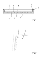
- FIG. 1 shows a sectional view of the solar collector according to the invention.
- the solar collector consists of an absorber 2, which is heated by solar radiation. The heat is dissipated via lines 3, which are flowed through by a heat transfer medium, to a heat sink, not shown here, where the heat is used as useful heat.
- the absorber is insulated on the back by means of an insulation 4.
- On the top of the absorber 2 is covered by a cover 1. This also serves isolation.
- a cavity 8 is provided between the absorber 2 and cover 1, which is filled with an inert gas or inert gas such as argon. Alternatively, a vacuum near negative pressure or a vacuum prevail in the cavity 8.
- the cavity 8 is sealed gas-tight from the environment.
- the seal is also at high temperatures, as they occur in the case of stagnation of the solar collector, resistant.
- the edge region of the absorber 2 is designed in the form of a collar 6, so that the cover plate 1 is connected directly to the absorber 2.
- the compound 7 is carried out according to the invention by a brazed joint or welded joint, preferably by an ultrasonic welding connection. Such connections between metal and glass can be reliably controlled.
- a brazed joint or welded joint is used using an intermediate layer made of a material between the cover plate 1 and the absorber 2 and which has particularly good soldering or welding properties with respect to the cover plate 1 or to the absorber 2.
- the compound 7 can also be designed sealingly with a silicone adhesive seam.
- the diffusing gas is contrasted with a small cross-sectional area and a long distance through which the gas must diffuse. This is achieved by an adhesive joint or adhesive seam that is less than 1 mm thick and over 10 mm wide.
- FIG. 2 shows the representation of a corner of an embodiment of the absorber 2.
- the absorber is made by a deep drawing of a flat sheet metal. In this case, a collar 6 is formed.
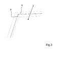
- FIG. 3 shows the same view of another embodiment of the absorber 2.
- the corners are cut out of a flat sheet metal and by folding the flat sheet is in the in FIG. 3 shown form brought with a collar 6. Subsequently, the seams are provided with a weld 9 to produce stability and gas tightness.
Landscapes
- Engineering & Computer Science (AREA)
- Physics & Mathematics (AREA)
- Life Sciences & Earth Sciences (AREA)
- Sustainable Development (AREA)
- Sustainable Energy (AREA)
- Thermal Sciences (AREA)
- Chemical & Material Sciences (AREA)
- Combustion & Propulsion (AREA)
- Mechanical Engineering (AREA)
- General Engineering & Computer Science (AREA)
- Joining Of Glass To Other Materials (AREA)
Applications Claiming Priority (1)
| Application Number | Priority Date | Filing Date | Title |
|---|---|---|---|
| DE102011116206A DE102011116206A1 (de) | 2011-10-15 | 2011-10-15 | Solarkollektor |
Publications (2)
| Publication Number | Publication Date |
|---|---|
| EP2581686A2 true EP2581686A2 (fr) | 2013-04-17 |
| EP2581686A3 EP2581686A3 (fr) | 2016-11-30 |
Family
ID=47046381
Family Applications (1)
| Application Number | Title | Priority Date | Filing Date |
|---|---|---|---|
| EP12186749.3A Withdrawn EP2581686A3 (fr) | 2011-10-15 | 2012-10-01 | Collecteur solaire |
Country Status (2)
| Country | Link |
|---|---|
| EP (1) | EP2581686A3 (fr) |
| DE (1) | DE102011116206A1 (fr) |
Citations (1)
| Publication number | Priority date | Publication date | Assignee | Title |
|---|---|---|---|---|
| DE20103503U1 (de) | 2001-02-23 | 2001-05-10 | Arnold & Stolzenberg GmbH, 37574 Einbeck | Gliederkette |
Family Cites Families (12)
| Publication number | Priority date | Publication date | Assignee | Title |
|---|---|---|---|---|
| US4010733A (en) * | 1975-06-03 | 1977-03-08 | The United States Of America As Represented By The United States Energy Research And Development Administration | Structurally integrated steel solar collector |
| US4098265A (en) * | 1976-05-10 | 1978-07-04 | Gravely Ben T | Solar energy collector |
| US4205658A (en) * | 1977-10-06 | 1980-06-03 | Clark Peter C | Heat transfer panel |
| US4279243A (en) * | 1977-11-14 | 1981-07-21 | Deakin David A | Solar collector panel |
| FR2423731A1 (fr) * | 1978-02-16 | 1979-11-16 | Vironneau Pierre | Capteur solaire modulaire |
| US4245619A (en) * | 1978-12-13 | 1981-01-20 | Ogilvie Michael B | Solar energy collection panel |
| SE434186B (sv) * | 1982-05-27 | 1984-07-09 | Inga Sundquist | Solmodul |
| DE10161085A1 (de) * | 2001-12-12 | 2003-06-18 | Berthold Fuertig | System zur Erzeugung von Wärme aus Sonnenenergie |
| DE102006006718B4 (de) * | 2005-11-17 | 2008-01-24 | Schütz, Hans | Solarkollektor |
| DE102008008015A1 (de) * | 2008-02-07 | 2009-08-13 | Erich Terbrack | Kollektorelement eines Sonnenkollektors und Sonnenkollektor |
| DE102010060289A1 (de) * | 2009-10-30 | 2011-05-19 | Schatz, Viktor, Dipl.-Ing. | Solarkollektor, Verbund-System und Solaranlage |
| DE102010002777B4 (de) * | 2010-03-11 | 2016-01-21 | Universität Kassel | Halbzeug für einen Solarkollektor, Solarkollektor und Verfahren zur Herstellung |
-
2011
- 2011-10-15 DE DE102011116206A patent/DE102011116206A1/de not_active Withdrawn
-
2012
- 2012-10-01 EP EP12186749.3A patent/EP2581686A3/fr not_active Withdrawn
Patent Citations (1)
| Publication number | Priority date | Publication date | Assignee | Title |
|---|---|---|---|---|
| DE20103503U1 (de) | 2001-02-23 | 2001-05-10 | Arnold & Stolzenberg GmbH, 37574 Einbeck | Gliederkette |
Also Published As
| Publication number | Publication date |
|---|---|
| DE102011116206A1 (de) | 2013-04-18 |
| EP2581686A3 (fr) | 2016-11-30 |
Similar Documents
| Publication | Publication Date | Title |
|---|---|---|
| EP0031479B1 (fr) | Collecteur solaire en forme de panneau | |
| EP2701190B1 (fr) | Procédé de fabrication d'un corps de refroidissement pour au moins un élément à refroidir | |
| EP2513400A2 (fr) | Élément de vitrage thermo-isolant et son procédé de production | |
| DE102012214701A1 (de) | Thermoelektrische Vorrichtung | |
| EP1830140A2 (fr) | Collecteur hybride | |
| EP2890938B1 (fr) | Module de bâtiment et procédé de fabrication d'un module de bâtiment | |
| EP2244031A2 (fr) | Collecteur solaire, vitrage composite et absorbeur ainsi qu'utilisation d'un tel absorbeur | |
| DE102008029676A1 (de) | Sonnenkollektor mit mikrostrukturierter Absorberfläche | |
| AT512140B1 (de) | Solarkollektor | |
| DE102010060289A1 (de) | Solarkollektor, Verbund-System und Solaranlage | |
| EP0846245A1 (fr) | Collecteur de chaleur solaire | |
| EP1095231A1 (fr) | Procede permettant de fabriquer un capteur solaire et un absorbeur destine audit capteur | |
| EP2581686A2 (fr) | Collecteur solaire | |
| DE19709653A1 (de) | Kombi-Solarelement | |
| DE19830345A1 (de) | Verfahren zum Herstellen eines Solarkollektors sowie eines Absorbers für einen Solarkollektor | |
| DE20010880U1 (de) | Hybrid-Solarkollektor | |
| DE202016003756U1 (de) | Photovoltaik-Modul mit Wärmetauscher für Solarstrahlungs- und Luft-Wärme | |
| EP0326605B1 (fr) | Paroi thermoconductrice composee de deux parties similaires a des plaques | |
| DE2726457A1 (de) | Sonnenkollektor mit einer abdeckung aus evakuierten rohren | |
| DE10161085A1 (de) | System zur Erzeugung von Wärme aus Sonnenenergie | |
| DE20219221U1 (de) | Sonnenkollektor | |
| DE102012110628A1 (de) | Gehäuse für einen thermischen Solarkollektor, Verfahren zur Herstellung eines Halbzeugs für ein solches Gehäuse, sowie thermischer Solarkollektor | |
| DE9406243U1 (de) | Inverser Absorber für Sonnenkollektoren | |
| EP2532985B1 (fr) | Collecteur solaire | |
| DE2615475C3 (de) | Sonnenkollektor mit einer Abdeckung aus evakuierten Rohren |
Legal Events
| Date | Code | Title | Description |
|---|---|---|---|
| PUAI | Public reference made under article 153(3) epc to a published international application that has entered the european phase |
Free format text: ORIGINAL CODE: 0009012 |
|
| AK | Designated contracting states |
Kind code of ref document: A2 Designated state(s): AL AT BE BG CH CY CZ DE DK EE ES FI FR GB GR HR HU IE IS IT LI LT LU LV MC MK MT NL NO PL PT RO RS SE SI SK SM TR |
|
| AX | Request for extension of the european patent |
Extension state: BA ME |
|
| PUAL | Search report despatched |
Free format text: ORIGINAL CODE: 0009013 |
|
| AK | Designated contracting states |
Kind code of ref document: A3 Designated state(s): AL AT BE BG CH CY CZ DE DK EE ES FI FR GB GR HR HU IE IS IT LI LT LU LV MC MK MT NL NO PL PT RO RS SE SI SK SM TR |
|
| AX | Request for extension of the european patent |
Extension state: BA ME |
|
| RIC1 | Information provided on ipc code assigned before grant |
Ipc: F24J 2/24 20060101AFI20161024BHEP Ipc: F24J 2/46 20060101ALI20161024BHEP |
|
| 17P | Request for examination filed |
Effective date: 20170529 |
|
| RBV | Designated contracting states (corrected) |
Designated state(s): AL AT BE BG CH CY CZ DE DK EE ES FI FR GB GR HR HU IE IS IT LI LT LU LV MC MK MT NL NO PL PT RO RS SE SI SK SM TR |
|
| STAA | Information on the status of an ep patent application or granted ep patent |
Free format text: STATUS: THE APPLICATION IS DEEMED TO BE WITHDRAWN |
|
| 18D | Application deemed to be withdrawn |
Effective date: 20190501 |