EP2581688A2 - Support destiné au montage d'un panneau solaire - Google Patents
Support destiné au montage d'un panneau solaire Download PDFInfo
- Publication number
- EP2581688A2 EP2581688A2 EP12006756.6A EP12006756A EP2581688A2 EP 2581688 A2 EP2581688 A2 EP 2581688A2 EP 12006756 A EP12006756 A EP 12006756A EP 2581688 A2 EP2581688 A2 EP 2581688A2
- Authority
- EP
- European Patent Office
- Prior art keywords
- solar panel
- carrier
- walls
- support
- clamping
- Prior art date
- Legal status (The legal status is an assumption and is not a legal conclusion. Google has not performed a legal analysis and makes no representation as to the accuracy of the status listed.)
- Withdrawn
Links
- 239000003351 stiffener Substances 0.000 claims description 12
- 230000000284 resting effect Effects 0.000 claims description 9
- 239000000969 carrier Substances 0.000 description 4
- 238000010276 construction Methods 0.000 description 3
- 230000003014 reinforcing effect Effects 0.000 description 3
- 101100498160 Mus musculus Dach1 gene Proteins 0.000 description 2
- 238000007664 blowing Methods 0.000 description 2
- 238000000748 compression moulding Methods 0.000 description 2
- 229910052751 metal Inorganic materials 0.000 description 2
- 239000002184 metal Substances 0.000 description 2
- 230000002787 reinforcement Effects 0.000 description 2
- 239000000758 substrate Substances 0.000 description 2
- 238000007666 vacuum forming Methods 0.000 description 2
- 244000059549 Borneo rubber Species 0.000 description 1
- 239000004698 Polyethylene Substances 0.000 description 1
- 238000009825 accumulation Methods 0.000 description 1
- 229910052782 aluminium Inorganic materials 0.000 description 1
- XAGFODPZIPBFFR-UHFFFAOYSA-N aluminium Chemical compound [Al] XAGFODPZIPBFFR-UHFFFAOYSA-N 0.000 description 1
- 238000013459 approach Methods 0.000 description 1
- 239000012050 conventional carrier Substances 0.000 description 1
- 230000001419 dependent effect Effects 0.000 description 1
- 230000000694 effects Effects 0.000 description 1
- 239000013013 elastic material Substances 0.000 description 1
- 239000011521 glass Substances 0.000 description 1
- 238000009434 installation Methods 0.000 description 1
- 238000004519 manufacturing process Methods 0.000 description 1
- 239000000463 material Substances 0.000 description 1
- 238000000034 method Methods 0.000 description 1
- 230000035515 penetration Effects 0.000 description 1
- 239000004033 plastic Substances 0.000 description 1
- 229920003023 plastic Polymers 0.000 description 1
- -1 polyethylene Polymers 0.000 description 1
- 229920000573 polyethylene Polymers 0.000 description 1
- 229920002635 polyurethane Polymers 0.000 description 1
- 239000004814 polyurethane Substances 0.000 description 1
- 239000010409 thin film Substances 0.000 description 1
- XLYOFNOQVPJJNP-UHFFFAOYSA-N water Substances O XLYOFNOQVPJJNP-UHFFFAOYSA-N 0.000 description 1
Images


Classifications
-
- F—MECHANICAL ENGINEERING; LIGHTING; HEATING; WEAPONS; BLASTING
- F24—HEATING; RANGES; VENTILATING
- F24S—SOLAR HEAT COLLECTORS; SOLAR HEAT SYSTEMS
- F24S25/00—Arrangement of stationary mountings or supports for solar heat collector modules
- F24S25/10—Arrangement of stationary mountings or supports for solar heat collector modules extending in directions away from a supporting surface
- F24S25/11—Arrangement of stationary mountings or supports for solar heat collector modules extending in directions away from a supporting surface using shaped bodies, e.g. concrete elements, foamed elements or moulded box-like elements
-
- F—MECHANICAL ENGINEERING; LIGHTING; HEATING; WEAPONS; BLASTING
- F24—HEATING; RANGES; VENTILATING
- F24S—SOLAR HEAT COLLECTORS; SOLAR HEAT SYSTEMS
- F24S80/00—Details, accessories or component parts of solar heat collectors not provided for in groups F24S10/00-F24S70/00
- F24S80/70—Sealing means
-
- F—MECHANICAL ENGINEERING; LIGHTING; HEATING; WEAPONS; BLASTING
- F24—HEATING; RANGES; VENTILATING
- F24S—SOLAR HEAT COLLECTORS; SOLAR HEAT SYSTEMS
- F24S25/00—Arrangement of stationary mountings or supports for solar heat collector modules
- F24S2025/01—Special support components; Methods of use
- F24S2025/013—Stackable support elements
-
- F—MECHANICAL ENGINEERING; LIGHTING; HEATING; WEAPONS; BLASTING
- F24—HEATING; RANGES; VENTILATING
- F24S—SOLAR HEAT COLLECTORS; SOLAR HEAT SYSTEMS
- F24S80/00—Details, accessories or component parts of solar heat collectors not provided for in groups F24S10/00-F24S70/00
- F24S2080/01—Selection of particular materials
- F24S2080/015—Plastics
-
- Y—GENERAL TAGGING OF NEW TECHNOLOGICAL DEVELOPMENTS; GENERAL TAGGING OF CROSS-SECTIONAL TECHNOLOGIES SPANNING OVER SEVERAL SECTIONS OF THE IPC; TECHNICAL SUBJECTS COVERED BY FORMER USPC CROSS-REFERENCE ART COLLECTIONS [XRACs] AND DIGESTS
- Y02—TECHNOLOGIES OR APPLICATIONS FOR MITIGATION OR ADAPTATION AGAINST CLIMATE CHANGE
- Y02B—CLIMATE CHANGE MITIGATION TECHNOLOGIES RELATED TO BUILDINGS, e.g. HOUSING, HOUSE APPLIANCES OR RELATED END-USER APPLICATIONS
- Y02B10/00—Integration of renewable energy sources in buildings
- Y02B10/20—Solar thermal
-
- Y—GENERAL TAGGING OF NEW TECHNOLOGICAL DEVELOPMENTS; GENERAL TAGGING OF CROSS-SECTIONAL TECHNOLOGIES SPANNING OVER SEVERAL SECTIONS OF THE IPC; TECHNICAL SUBJECTS COVERED BY FORMER USPC CROSS-REFERENCE ART COLLECTIONS [XRACs] AND DIGESTS
- Y02—TECHNOLOGIES OR APPLICATIONS FOR MITIGATION OR ADAPTATION AGAINST CLIMATE CHANGE
- Y02E—REDUCTION OF GREENHOUSE GAS [GHG] EMISSIONS, RELATED TO ENERGY GENERATION, TRANSMISSION OR DISTRIBUTION
- Y02E10/00—Energy generation through renewable energy sources
- Y02E10/40—Solar thermal energy, e.g. solar towers
- Y02E10/47—Mountings or tracking
Definitions
- the invention relates to a support for supporting or mounting a solar panel on a roof, such as a flat roof.
- the invention relates to an arrangement consisting of such a carrier and a mounted on this solar panel.
- the European Patent Publication EP 0 857 926 A1 describes an example of a known support for a solar panel.
- This carrier has a trough-shaped or box-shaped construction with a flat upper edge, which serves as a support surface for the solar panel.
- the Sotar panels have an aluminum frame that extends around the perimeter of the panel. The solar panel is attached to this frame at the top and bottom of the carrier by means of screws.
- the new generation of solar panels are lighter, thinner modules made without metal frames.
- the invention is therefore based on the object to provide a new support for solar panels, especially for thin-layer, frameless solar panels, with which a solar panel can be easily positioned and reliably and securely attached.
- Fastening means for fixing the solar panel on the support surfaces, wherein the fastening means clamp the solar panel against the support surfaces.
- the clamping is carried out over at least half, and preferably at least 3 ⁇ 4, of an elongated dimension of a lateral edge of the resting on the support surfaces solar panel.
- the fastening means comprise at least one clamping rail mounted on a lateral edge of the solar panel resting on the support surfaces and extending (preferably continuously) over at least half of the elongated dimension of the lateral edge of the solar panel. More preferably, the fastening means comprise at least two clamping rails which extend continuously over at least half of the elongated dimension of two opposite lateral edges of the solar panel.
- the support surfaces extend substantially in a plane and throughout at least half, preferably at least 3 ⁇ 4, and more preferably the whole, the elongated dimension of one lateral edge, preferably two opposite lateral edges of the solar panel.
- the new solar panels are relatively thin (for example, with a wall thickness in the range of 6 to 7 mm) and consist of only partially flexible, relatively light and therefore sensitive glass layers, it is important to secure such solar panels so reliable and secure as possible.
- the inventors have found that the lateral edges of the panel should rest flat over more than half of their lengths on the support surfaces and be clamped thereon.
- the mounting system of the present invention it is possible to dispense with a metal frame for the solar panels.
- the frame of the solar panel is effectively replaced by the clamping rails, which not only lead to a simplified and cheaper production of the panels, but also to a faster and more reliable installation of the panels.
- each clamping rail has a cover part directly attached to the lateral edge of the solar panel and a fixing part extending outside a periphery of the solar panel.
- the walls of the carrier have an upper edge, e.g. B. in the form of a flange, at its upper, the lower part opposite sides, which edge or flange, the support surfaces at least partially includes and the clamping rail (s) also supported.
- the rim or flange extends around the upper circumference of the walls.
- the upper edge or flange preferably extends outside the circumference of the solar panel resting on the support surfaces, and the fixing part of the clamping rail (s) is attached and fixed to the edge or flange.
- the at least one clamping rail is fixed with one or more screw (s).
- the fasteners also include lugs for receiving screws, which lugs are on a lower side of the upper rim or flange, and preferably formed integrally with the rim or flange and / or with the walls of the carrier. If the lugs or bushes are properly adapted to the screws, the clamping rails and thus also the solar panel can be fixed by simply screwing it onto the carrier. In other words, an installer does not need a nut for the screws. The screws engage in the material of the lugs or bushes and thus create a firm fixation of the rail to the respective flange. Two or three screws per clamping rail are preferably used.
- the at least one clamping rail on a resilient or elastic element which absorbs the clamping pressure and distributes it over the lateral edge of the solar panel.
- the resilient or elastic element is z. B. in the cover part of the at least one clamping rail.
- the lower part of the carrier consists mainly of a bottom, on whose circumference the walls rise, so that the bottom and the walls together form a chamber for receiving ballast and preferably provide a trough-shaped or box-shaped structure of the carrier ,
- the ballast chamber may be filled with loose poured ballast, such as gravel already present on a roof, or with stones inside it to hold the carrier in place.
- the walls of the carrier preferably comprise a high rear wall, a low front wall, and two lateral walls which are interconnected and laterally enclose the chamber.
- the edge or the flange runs around the upper circumference of the walls.
- the different heights of the rear and front walls of the carrier determine an oblique attitude of the resting on the support surfaces solar panel with respect to the floor or the roof level.
- the solar panel at an angle of 10 to 40 degrees with respect to the roof plane. More preferably, the solar panel is at an angle of 10 to 20 degrees with respect to the roof plane. Of course, this angle will not be optimal for the individual solar panel in Northern Europe, but several carriers can thus be so closely packed without mutual shadow effect that the efficiency for a fully occupied roof is very satisfactory.
- the walls and / or the bottom are preferably formed with parallel protrusions to provide a stronger and more stable structure.
- the carrier comprises a stiffener insertable between the walls, the walls having means for mounting this stiffener.
- the stiffening is preferably formed as at least one strut and the means for mounting the stiffener may have recesses or recesses in the walls for attaching or inserting the strut.
- This strut is preferably inserted between the rear and front walls and is particularly advantageous in areas where it can snow.
- An additional stiffening therefore increases the rigidity and thus the stability of the arrangement in areas where winter often brings snow.
- This stiffening, z. B. in the form of at least one strut is preferably used below the solar panel and can also provide an additional support surface for the panel.
- Fastening means for fixing the solar panel on the support surfaces, wherein the fastening means are suitable for clamping the solar panel against the support surfaces.
- the walls of the carrier on means for mounting a usable between the walls stiffening.
- the stiffener is preferably formed as a strut and the mounting means comprise recesses in the walls for attaching the strut.
- the support surfaces comprise at least one side surface which supports an edge of the solar panel and serves to position the solar panel on the support.
- the carrier has at least one stop on or at the upper edge or flange, which stop comprises the said side surface.
- the at least one stop is located at the upper edge or flange of the front wall of the carrier.
- the carrier is shaped such that it can be stacked by nesting on an identical carrier. Multiple carriers can be transported compactly stacked when the carrier is shaped to be stacked by nesting on a same carrier.
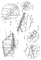
- the carrier 1 comprises a lower part 10 for placing the carrier on a substantially flat surface, and in particular on a roof.
- the lower part 10 consists mainly of a bottom 11, which is formed from a plate and with parallel protrusions or recesses 12.
- the parallel projections or recesses 12 form a ribbed bottom profile and thus increase the flexural strength and stability of the bottom 11.
- Two rows of holes 13 through the bottom plate 11 are provided for drainage of rain water or moisture.
- the four walls 20 extend, which, together with the bottom 11, give the carrier 1 a trough-shaped or box-shaped construction.
- the four walls 20 include a high rear wall 21, a low front wall 22, and two lateral walls 23 which are interconnected and together with the bottom 11 form a ballast receiving chamber 30.
- the walls 20 have parallel protrusions 24 which, as reinforcing ribs, make the structure and profile of the carrier 1 stiffer and more stable. This stability is particularly advantageous when the carrier 1 is exposed to higher loads of wind and snow.
- the walls 20 are bounded by an upper edge 25, which edge 25 includes support surfaces for placing the solar panel S.
- the edge 25 is formed in the form of a flange and constitutes a continuous flat support surface 26, which extends over the entire lateral extent of the carrier.
- the edge 25 is uneven and not continuous flat by recesses or recesses 27, 27 '.
- both the upper edge 25 of the rear wall 21 and the upper edge 25 of the front wall 22 has a plurality of lying in the same plane support surfaces 28 for the solar panel S. In other words, the solar panel S is placed on the support surfaces 26, 28 and of these supported.
- the lateral flanges 25 have a series of spaced fixation holes 29 which serve as attachment means for attaching the solar panel S.
- Each of these fixing holes 29 extends through the respective flange 25 and a formed below the flange 25 lug 31, which serves as a tubular socket for receiving a Screw is used.
- the underside of the flange 25 and thus also the sides of the lugs 31 are provided with reinforcing webs 32 to provide a stronger and more stable mounting structure.
- the centrally located support surfaces 28 of the rear and front walls 21, 22 also have further fixing holes 33 with tubular lugs or bushings 34 which are also stably formed by reinforcing webs 35 with the upper edge 25 of the front and rear walls 21, 22 ,
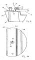
- the fastening means for fixing the solar panel S on the carrier 1 have two lateral clamping rails 40, which are suitable for clamping the solar panel against the support surfaces 26 of the flanges 25.
- Each clamping rail 40 comprises a cover part 41 which is attached via a lateral edge to an edge region of the solar panel S resting on the support surfaces 26, and a fixing part 42 which extends beyond the flange 25 outside the periphery of the solar panel S. It is important that the clamping rails 40 continuously span over at least half and preferably at least three quarters of the elongated dimension of the lateral edge of the solar panel S against the support surfaces 26 of the flanges 25. In this way, the thin-film module S is stably mounted on the carrier 1.
- the fixing part 42 of the clamping rail 40 is provided with oblong holes 43 which can be brought into agreement with the fixing holes 29 by the flange 25, so that screws 44 can be screwed through the rail 40 in the lugs 31 and bushes to the rail 40th and thus to fix the solar panel S in position on the carrier 1.
- the elongated holes 43 have a certain play in the lateral direction with respect to the holes 29 in order to allow an adjustment and precise positioning of the clamping rails 40.
- each clamping rail 40 has a resilient element 45 made of a relatively soft, elastic material, such. B. rubber or similar, which element 45 in a recess 46 at a lower side along the cover part 41 is arranged.
- the elastic element 45 makes the clamping contact with the upper edge region of the solar panel S, rebounds the clamping pressure and distributes it along the lateral edge of the resting on the lateral support surfaces 26 solar panel S.
- the new thin-layer solar panels or modules are rectangular and have a typical size of about 1.1 m x 1.3 m. These panels are normally oriented such that the longer sides (of 1.3 m) extend between the rear and front walls 21, 22 of the carrier and are supported on the lateral edges or flanges 25.
- the solar cells in the modules are arranged such that an edge region of the solar panel of about 5 to 15 mm (for example 10 mm) generates no current and is thus very well suited for attachment to the lateral clamping rails 40. In other words, the cover part 41 of the clamping rail 40 can easily cover this edge region.
- FIGS. 5A and 5B show z. B. elevations 36 on the left and right sides of the front wall 22. These elevations 36 form stops that serve a stable positioning and mounting of the solar panel S on the carrier.
- Each stop 36 has a rear side surface 37 and a lower surface 38, which act as further support surfaces for the front and lower edge E of the solar panel S.
- the front and bottom edges E of the solar panel S are supported against the side surfaces 37 and centered on the carrier 1, whereafter the clamping rails 40 can be fixed to the edges of the panel.
- the side surfaces 37 of the stops 36 therefore function as a slip-off protection for the solar panel S and the lower surfaces 38 of the stops 36 are in one plane with the other support surfaces 26, 28th
- each of these recesses 27 serves as a means for mounting a stiffening of the carrier;
- each recess 27 is suitable for receiving a respective end of a stiffening strut (not shown).
- the strut is received in the recesses 27 so that it extends between the front and rear walls 21, 22, and that its upper side forms an additional support surface for the solar panel S.
- the strut causes stiffening and reinforcement of the carrier 1 in the direction between the front and rear walls.
- Such a strut is in the embodiment of FIGS. 6 to 8B shown more clearly.
- FIGS. 5E and 5F show another recess or notch 27 'in the rear wall 21 of the carrier.
- the cables which connect the solar cells of the panels or the modules with a local power consumer or consumer network or with a storage system can be guided through these notches 27 'and through the chamber 30 of the carrier 1.
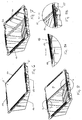
- FIGS. 6 and 7 an arrangement according to the invention is shown, consisting of a support 1 according to the invention and a solar panel S mounted thereon.
- the lateral clamping rails 40 can be clearly seen.
- These further clamping rails 50 are in close-up in the FIGS. 8 to 8B shown.
- the shape or construction of the clamping rails 50 corresponds to that in the FIGS. 4 and 4A shown lateral clamping rails 40 and they are fixed to the rear and front edge of the carrier or the panel.
- Additional rails 50 function as a wind suction protection against the suction force of a northbound wind blowing from behind over the carrier and the solar panel mounted thereon.
- the high side of the beam 1 is always directed north to align the solar panel with the sun.
- the chamber 30 of the box-shaped carrier 1 is filled with ballast to hold it in place. This can z. B. already existing on the roof gravel, which was originally in the place of the carrier, or paving stones, which are supplied for this purpose with. Since the solar panel S is relatively thin, the suction force of the wind blowing over the support could be strong enough to strongly bend a panel unsecured at its upper edge, or even tear it from the wearer.
- the upper and lower clamping rails 50 therefore serve as a backup for the solar panel S against such wind suction.
- stiffening strut 60 In the FIGS. 7 and 8 is a between the front and rear walls 21, 22 extending stiffening strut 60 also clearly visible. The respective ends of this strut 60 are inserted into the opposing recesses 27 and the upper side 61 forms an additional support surface for the solar panel S.
- the strut 60 causes stiffening and reinforcement of the carrier 1, which significantly improves the load capacity of the wearer in snowfall.
- the inclination of the walls 20 of the carrier 1, which protrude from the bottom 11 upwards, is set so that the carrier 1 is self-releasing from the mold after vacuum forming or injection-compression molding.
- This shape a plurality of carriers 1 are nestable in the vertical direction, creating a compact stack that is easy to transport.
- This nestable form of the carrier is particularly important because a relatively large number of carriers and solar panels are typically installed on a single roof, e.g. B. in directly adjacent rows that completely cover a large part of the roof area.
- the carrier according to the invention is preferably made of a plastic, such as. As polyurethane, polyethylene o. A., Made in an injection-compression molding method, although a vacuum-forming of the carrier is also possible.
Landscapes
- Engineering & Computer Science (AREA)
- Physics & Mathematics (AREA)
- Life Sciences & Earth Sciences (AREA)
- Sustainable Development (AREA)
- Sustainable Energy (AREA)
- Thermal Sciences (AREA)
- Chemical & Material Sciences (AREA)
- Combustion & Propulsion (AREA)
- Mechanical Engineering (AREA)
- General Engineering & Computer Science (AREA)
- Roof Covering Using Slabs Or Stiff Sheets (AREA)
Priority Applications (1)
| Application Number | Priority Date | Filing Date | Title |
|---|---|---|---|
| EP12006756.6A EP2581688A3 (fr) | 2008-11-11 | 2008-11-11 | Support destiné au montage d'un panneau solaire |
Applications Claiming Priority (2)
| Application Number | Priority Date | Filing Date | Title |
|---|---|---|---|
| EP12006756.6A EP2581688A3 (fr) | 2008-11-11 | 2008-11-11 | Support destiné au montage d'un panneau solaire |
| EP08019706A EP2184560A1 (fr) | 2008-11-11 | 2008-11-11 | Support destiné au montage d'un panneau solaire |
Related Parent Applications (1)
| Application Number | Title | Priority Date | Filing Date |
|---|---|---|---|
| EP08019706.4 Division | 2008-11-11 |
Publications (2)
| Publication Number | Publication Date |
|---|---|
| EP2581688A2 true EP2581688A2 (fr) | 2013-04-17 |
| EP2581688A3 EP2581688A3 (fr) | 2013-06-19 |
Family
ID=40935069
Family Applications (3)
| Application Number | Title | Priority Date | Filing Date |
|---|---|---|---|
| EP08019706A Ceased EP2184560A1 (fr) | 2008-11-11 | 2008-11-11 | Support destiné au montage d'un panneau solaire |
| EP12006756.6A Withdrawn EP2581688A3 (fr) | 2008-11-11 | 2008-11-11 | Support destiné au montage d'un panneau solaire |
| EP09752294A Withdrawn EP2344816A1 (fr) | 2008-11-11 | 2009-11-10 | Support pour monter un panneau solaire |
Family Applications Before (1)
| Application Number | Title | Priority Date | Filing Date |
|---|---|---|---|
| EP08019706A Ceased EP2184560A1 (fr) | 2008-11-11 | 2008-11-11 | Support destiné au montage d'un panneau solaire |
Family Applications After (1)
| Application Number | Title | Priority Date | Filing Date |
|---|---|---|---|
| EP09752294A Withdrawn EP2344816A1 (fr) | 2008-11-11 | 2009-11-10 | Support pour monter un panneau solaire |
Country Status (3)
| Country | Link |
|---|---|
| US (1) | US20120031469A1 (fr) |
| EP (3) | EP2184560A1 (fr) |
| WO (1) | WO2010054795A1 (fr) |
Families Citing this family (25)
| Publication number | Priority date | Publication date | Assignee | Title |
|---|---|---|---|---|
| DE102007045554B3 (de) * | 2007-09-24 | 2009-03-19 | Solarworld Ag | Stapelbares Flachdach-/Bodengestell für Solarpaneele |
| US20120110931A1 (en) * | 2007-11-01 | 2012-05-10 | Patrina Eiffert | Isolation mount and methods therefor |
| US9831817B2 (en) * | 2009-03-03 | 2017-11-28 | Elie Rothschild | Solar panel mounting base and system for solar panel installation |
| DE102010029002A1 (de) * | 2010-05-17 | 2011-11-17 | Hilti Aktiengesellschaft | Montagefuss für Solarmodule sowie Montagesystem mit mehreren solcher Montagefüsse |
| DE102010023562A1 (de) * | 2010-06-09 | 2011-12-15 | Solon Se | Tragplatte zur Lagerung von Solarmodulen auf einem Flachsubstrat und Tragplattenfeld |
| GB2487914B (en) * | 2011-02-07 | 2015-03-11 | Solar Roof Invest Ltd | Solar panel assemblies |
| US20120240490A1 (en) * | 2011-03-25 | 2012-09-27 | Gangemi Ronald J | Roof mounted photovoltaic system with accessible panel electronics |
| EP2525164A1 (fr) * | 2011-05-20 | 2012-11-21 | Maspi S.r.L. | Structure de support de panneaux solaires |
| US8850754B2 (en) * | 2011-10-17 | 2014-10-07 | Dynoraxx, Inc. | Molded solar panel racking assembly |
| US8418419B1 (en) * | 2011-11-08 | 2013-04-16 | Johns Manville | Base unit for mounting photovoltaic modules |
| JP5912797B2 (ja) * | 2012-04-16 | 2016-04-27 | 三甲株式会社 | ソーラーパネル装置及びその製造方法 |
| JP2013221287A (ja) * | 2012-04-16 | 2013-10-28 | Sanko Co Ltd | ソーラーパネル装置 |
| US9194611B2 (en) | 2012-06-05 | 2015-11-24 | Saudi Arabian Oil Company | Self-ballasted, roof-integrated, lightweight FRC PV mounting system |
| US9249925B2 (en) | 2013-07-03 | 2016-02-02 | Unirac, Inc. | Apparatus for mounting a photovoltaic module |
| DE102014106800B4 (de) | 2014-02-26 | 2015-11-12 | Eisenwerk Wittigsthal Gmbh | Ständeranordnung für ein Solarpaneel |
| EP3164647A1 (fr) * | 2014-07-03 | 2017-05-10 | Basf Se | Support de montage en plastique destiné à des panneaux solaires |
| USD800055S1 (en) * | 2015-06-11 | 2017-10-17 | Elie Rothschild | Solar panel attachment base |
| WO2016200393A1 (fr) * | 2015-06-11 | 2016-12-15 | Elie Rothschild | Base de montage de panneau solaire et système d'installation de panneau solaire |
| US10250181B2 (en) | 2015-10-15 | 2019-04-02 | RBI Solar, Inc. | Solar panel support devices and related solar panel support systems |
| WO2017070393A1 (fr) * | 2015-10-20 | 2017-04-27 | Marvell World Trade Ltd. | Unité de données d'accusé de réception pour de multiples unités de données de liaison montante |
| CN109563707B (zh) * | 2016-06-17 | 2022-01-18 | 力场能源有限责任公司 | 太阳能模块安装和支撑系统 |
| TWI615590B (zh) * | 2016-09-12 | 2018-02-21 | 藍天電腦股份有限公司 | 太陽能板及其桶式支架 |
| FR3145205B1 (fr) | 2023-01-20 | 2025-10-31 | Helioslite | Structure à lests pour panneaux solaires. |
| EP4524493A1 (fr) * | 2023-09-15 | 2025-03-19 | Solardirekt Systems GmbH | Support pour la mise en place d'au moins un module solaire sur un sous-sol et procédé de disposition d'au moins un module solaire sur un tel support |
| DE102023130837A1 (de) * | 2023-11-07 | 2025-05-08 | Robert Zimmermann | Solarmodulbefestigungsvorrichtung |
Citations (1)
| Publication number | Priority date | Publication date | Assignee | Title |
|---|---|---|---|---|
| EP0857926A1 (fr) | 1997-02-06 | 1998-08-12 | Coöperatief Advies en Onderzoeksburo u.a. Ecofys | Dispositif pour supporter un panneau solaire et panneau solaire comprenant ce dispositif |
Family Cites Families (10)
| Publication number | Priority date | Publication date | Assignee | Title |
|---|---|---|---|---|
| US4114595A (en) * | 1977-07-06 | 1978-09-19 | Harold Reed Barker | Solar energy collector and glazing system |
| US4993583A (en) * | 1989-04-14 | 1991-02-19 | Coats & Clark | Display container |
| JP4776087B2 (ja) * | 2001-04-26 | 2011-09-21 | 京セラ株式会社 | 屋根パネル及びそれを用いた屋根アレイ |
| JP3727871B2 (ja) * | 2001-08-27 | 2005-12-21 | 三菱重工業株式会社 | 太陽電池パネル用架台 |
| DE20200672U1 (de) * | 2002-01-17 | 2002-06-20 | VACU-FORM Wischemann GmbH & Co.KG,, 48499 Salzbergen | Halterung für Solarmodule |
| DE10321422B4 (de) * | 2003-05-12 | 2005-09-29 | PRIMA Bau- und Dämmsysteme Ges. m.b.H. & Co. KG | Sonnenkollektor |
| NL1031317C2 (nl) | 2006-03-07 | 2007-09-10 | Ubbink Econergy Solar Gmbh | Steun voor zonnepaneel. |
| DE102006026297B3 (de) * | 2006-06-02 | 2007-08-09 | Solardirekt Gmbh & Co. Kg | Längenvariable Vorrichtung zum Tragen eines oder mehrerer Solarpaneele |
| DE202007008659U1 (de) * | 2007-06-18 | 2007-08-23 | Solarmarkt Ag | Solarmodul-Montagesystem |
| NL2001092C2 (nl) * | 2007-12-14 | 2009-06-16 | Renusol Gmbh | Drager voor een zonnepaneel. |
-
2008
- 2008-11-11 EP EP08019706A patent/EP2184560A1/fr not_active Ceased
- 2008-11-11 EP EP12006756.6A patent/EP2581688A3/fr not_active Withdrawn
-
2009
- 2009-11-10 US US13/128,461 patent/US20120031469A1/en not_active Abandoned
- 2009-11-10 WO PCT/EP2009/008019 patent/WO2010054795A1/fr not_active Ceased
- 2009-11-10 EP EP09752294A patent/EP2344816A1/fr not_active Withdrawn
Patent Citations (1)
| Publication number | Priority date | Publication date | Assignee | Title |
|---|---|---|---|---|
| EP0857926A1 (fr) | 1997-02-06 | 1998-08-12 | Coöperatief Advies en Onderzoeksburo u.a. Ecofys | Dispositif pour supporter un panneau solaire et panneau solaire comprenant ce dispositif |
Also Published As
| Publication number | Publication date |
|---|---|
| WO2010054795A1 (fr) | 2010-05-20 |
| EP2581688A3 (fr) | 2013-06-19 |
| US20120031469A1 (en) | 2012-02-09 |
| EP2344816A1 (fr) | 2011-07-20 |
| EP2184560A1 (fr) | 2010-05-12 |
Similar Documents
| Publication | Publication Date | Title |
|---|---|---|
| EP2581688A2 (fr) | Support destiné au montage d'un panneau solaire | |
| DE69815168T2 (de) | Stützvorrichtung für ein Solarpaneel und Aufbau mit einer solchen Stützvorrichtung | |
| DE102006026297B3 (de) | Längenvariable Vorrichtung zum Tragen eines oder mehrerer Solarpaneele | |
| DE102008037964A1 (de) | Montagevorrichtung für Solarmodule mit einem großen Aspektverhältnis | |
| EP2040014A2 (fr) | Structure au sol / à toit plat empilable pour panneaux solaires | |
| EP2223345A1 (fr) | Support pour un panneau solaire | |
| WO2013113307A2 (fr) | Corps flottant en forme de plaque et ensemble de corps flottants en forme de plaque | |
| EP2296190A2 (fr) | Agencement, sous-structure et installation photovoltaïque | |
| DE102009025365A1 (de) | Doppelniveauklammer für Photovoltaikmodule | |
| DE202011100205U1 (de) | Unterkonstruktion für Solaranlage sowie Solaranlage | |
| WO2009040081A1 (fr) | Support de sol/toit plat empilable pour panneaux solaires | |
| EP2385323A2 (fr) | Châssis de fixation de modules solaires | |
| EP2395299A1 (fr) | Plaque de support pour le stockage de modules solaires sur un substrat plat et ensemble de plaques de support | |
| DE202010015817U1 (de) | Solarmodulanordnung | |
| DE102009054242A1 (de) | Vorrichtung zur Befestigung mindestens eines Solarmoduls | |
| WO2011082730A2 (fr) | Dispositif de support de module solaire | |
| DE102006061284A1 (de) | Plattenförmiges photovoltaisches Solarmodul mit Rahmen aus Formprofilen | |
| DE102005032859B3 (de) | Befestigungssystem für Solarmodule | |
| DE202009002040U1 (de) | Halterung für ein Solarmodul | |
| EP2522928B1 (fr) | Dispositif destiné au montage de constructions sur une surface plane ou une surface à faible inclinaison | |
| EP2447620A1 (fr) | Dispositif d'agencement de panneaux solaires et/ou de collecteurs de chaleur sur une base ainsi que système comprenant au moins deux de ces dispositifs | |
| DE102021119422A1 (de) | Anordnung mit Solarmodulen zur Abtrennung eines ersten Raumbereichs von einem zweiten Raumbereich | |
| DE102021104862A1 (de) | Traggestell zu einer schrägen Befestigung eines Solarmoduls auf einem Dach | |
| DE102011122340A1 (de) | Photovoltaikanlage und ein Verfahren zur Herstellung einer Photovoltaikanlage | |
| EP2525163B1 (fr) | Unité de transport pour module solaire |
Legal Events
| Date | Code | Title | Description |
|---|---|---|---|
| PUAI | Public reference made under article 153(3) epc to a published international application that has entered the european phase |
Free format text: ORIGINAL CODE: 0009012 |
|
| AC | Divisional application: reference to earlier application |
Ref document number: 2184560 Country of ref document: EP Kind code of ref document: P |
|
| AK | Designated contracting states |
Kind code of ref document: A2 Designated state(s): AT BE BG CH CY CZ DE DK EE ES FI FR GB GR HR HU IE IS IT LI LT LU LV MC MT NL NO PL PT RO SE SI SK TR |
|
| PUAL | Search report despatched |
Free format text: ORIGINAL CODE: 0009013 |
|
| AK | Designated contracting states |
Kind code of ref document: A3 Designated state(s): AT BE BG CH CY CZ DE DK EE ES FI FR GB GR HR HU IE IS IT LI LT LU LV MC MT NL NO PL PT RO SE SI SK TR |
|
| RAP1 | Party data changed (applicant data changed or rights of an application transferred) |
Owner name: RENUSOL GMBH |
|
| RIC1 | Information provided on ipc code assigned before grant |
Ipc: F24J 2/46 20060101ALI20130514BHEP Ipc: F24J 2/52 20060101AFI20130514BHEP |
|
| STAA | Information on the status of an ep patent application or granted ep patent |
Free format text: STATUS: THE APPLICATION IS DEEMED TO BE WITHDRAWN |
|
| 18D | Application deemed to be withdrawn |
Effective date: 20131220 |