EP2581714B1 - Procédé et dispositif de détermination d'une vitesse d'écoulement absolue d'un flux massique ou volumique - Google Patents
Procédé et dispositif de détermination d'une vitesse d'écoulement absolue d'un flux massique ou volumique Download PDFInfo
- Publication number
- EP2581714B1 EP2581714B1 EP12187952.2A EP12187952A EP2581714B1 EP 2581714 B1 EP2581714 B1 EP 2581714B1 EP 12187952 A EP12187952 A EP 12187952A EP 2581714 B1 EP2581714 B1 EP 2581714B1
- Authority
- EP
- European Patent Office
- Prior art keywords
- reference value
- flow speed
- fluctuations
- determined
- absolute
- Prior art date
- Legal status (The legal status is an assumption and is not a legal conclusion. Google has not performed a legal analysis and makes no representation as to the accuracy of the status listed.)
- Active
Links
Images


Classifications
-
- G—PHYSICS
- G01—MEASURING; TESTING
- G01F—MEASURING VOLUME, VOLUME FLOW, MASS FLOW OR LIQUID LEVEL; METERING BY VOLUME
- G01F1/00—Measuring the volume flow or mass flow of fluid or fluent solid material wherein the fluid passes through a meter in a continuous flow
- G01F1/05—Measuring the volume flow or mass flow of fluid or fluent solid material wherein the fluid passes through a meter in a continuous flow by using mechanical effects
- G01F1/34—Measuring the volume flow or mass flow of fluid or fluent solid material wherein the fluid passes through a meter in a continuous flow by using mechanical effects by measuring pressure or differential pressure
- G01F1/36—Measuring the volume flow or mass flow of fluid or fluent solid material wherein the fluid passes through a meter in a continuous flow by using mechanical effects by measuring pressure or differential pressure the pressure or differential pressure being created by the use of flow constriction
- G01F1/38—Measuring the volume flow or mass flow of fluid or fluent solid material wherein the fluid passes through a meter in a continuous flow by using mechanical effects by measuring pressure or differential pressure the pressure or differential pressure being created by the use of flow constriction the pressure or differential pressure being measured by means of a movable element, e.g. diaphragm, piston, Bourdon tube or flexible capsule
- G01F1/383—Measuring the volume flow or mass flow of fluid or fluent solid material wherein the fluid passes through a meter in a continuous flow by using mechanical effects by measuring pressure or differential pressure the pressure or differential pressure being created by the use of flow constriction the pressure or differential pressure being measured by means of a movable element, e.g. diaphragm, piston, Bourdon tube or flexible capsule with electrical or electro-mechanical indication
-
- G—PHYSICS
- G01—MEASURING; TESTING
- G01F—MEASURING VOLUME, VOLUME FLOW, MASS FLOW OR LIQUID LEVEL; METERING BY VOLUME
- G01F1/00—Measuring the volume flow or mass flow of fluid or fluent solid material wherein the fluid passes through a meter in a continuous flow
- G01F1/05—Measuring the volume flow or mass flow of fluid or fluent solid material wherein the fluid passes through a meter in a continuous flow by using mechanical effects
- G01F1/20—Measuring the volume flow or mass flow of fluid or fluent solid material wherein the fluid passes through a meter in a continuous flow by using mechanical effects by detection of dynamic effects of the flow
- G01F1/32—Measuring the volume flow or mass flow of fluid or fluent solid material wherein the fluid passes through a meter in a continuous flow by using mechanical effects by detection of dynamic effects of the flow using swirl flowmeters
- G01F1/3209—Measuring the volume flow or mass flow of fluid or fluent solid material wherein the fluid passes through a meter in a continuous flow by using mechanical effects by detection of dynamic effects of the flow using swirl flowmeters using Karman vortices
-
- G—PHYSICS
- G01—MEASURING; TESTING
- G01F—MEASURING VOLUME, VOLUME FLOW, MASS FLOW OR LIQUID LEVEL; METERING BY VOLUME
- G01F1/00—Measuring the volume flow or mass flow of fluid or fluent solid material wherein the fluid passes through a meter in a continuous flow
- G01F1/05—Measuring the volume flow or mass flow of fluid or fluent solid material wherein the fluid passes through a meter in a continuous flow by using mechanical effects
- G01F1/20—Measuring the volume flow or mass flow of fluid or fluent solid material wherein the fluid passes through a meter in a continuous flow by using mechanical effects by detection of dynamic effects of the flow
- G01F1/32—Measuring the volume flow or mass flow of fluid or fluent solid material wherein the fluid passes through a meter in a continuous flow by using mechanical effects by detection of dynamic effects of the flow using swirl flowmeters
- G01F1/325—Means for detecting quantities used as proxy variables for swirl
- G01F1/3259—Means for detecting quantities used as proxy variables for swirl for detecting fluid pressure oscillations
-
- G—PHYSICS
- G01—MEASURING; TESTING
- G01F—MEASURING VOLUME, VOLUME FLOW, MASS FLOW OR LIQUID LEVEL; METERING BY VOLUME
- G01F1/00—Measuring the volume flow or mass flow of fluid or fluent solid material wherein the fluid passes through a meter in a continuous flow
- G01F1/05—Measuring the volume flow or mass flow of fluid or fluent solid material wherein the fluid passes through a meter in a continuous flow by using mechanical effects
- G01F1/34—Measuring the volume flow or mass flow of fluid or fluent solid material wherein the fluid passes through a meter in a continuous flow by using mechanical effects by measuring pressure or differential pressure
- G01F1/50—Correcting or compensating means
-
- G—PHYSICS
- G01—MEASURING; TESTING
- G01F—MEASURING VOLUME, VOLUME FLOW, MASS FLOW OR LIQUID LEVEL; METERING BY VOLUME
- G01F1/00—Measuring the volume flow or mass flow of fluid or fluent solid material wherein the fluid passes through a meter in a continuous flow
- G01F1/66—Measuring the volume flow or mass flow of fluid or fluent solid material wherein the fluid passes through a meter in a continuous flow by measuring frequency, phase shift or propagation time of electromagnetic or other waves, e.g. using ultrasonic flowmeters
- G01F1/666—Measuring the volume flow or mass flow of fluid or fluent solid material wherein the fluid passes through a meter in a continuous flow by measuring frequency, phase shift or propagation time of electromagnetic or other waves, e.g. using ultrasonic flowmeters by detecting noise and sounds generated by the flowing fluid
-
- G—PHYSICS
- G01—MEASURING; TESTING
- G01F—MEASURING VOLUME, VOLUME FLOW, MASS FLOW OR LIQUID LEVEL; METERING BY VOLUME
- G01F15/00—Details of, or accessories for, apparatus of groups G01F1/00 - G01F13/00 insofar as such details or appliances are not adapted to particular types of such apparatus
- G01F15/02—Compensating or correcting for variations in pressure, density or temperature
- G01F15/028—Compensating or correcting for variations in pressure, density or temperature for low flow rates
-
- G—PHYSICS
- G01—MEASURING; TESTING
- G01F—MEASURING VOLUME, VOLUME FLOW, MASS FLOW OR LIQUID LEVEL; METERING BY VOLUME
- G01F25/00—Testing or calibration of apparatus for measuring volume, volume flow or liquid level or for metering by volume
- G01F25/10—Testing or calibration of apparatus for measuring volume, volume flow or liquid level or for metering by volume of flowmeters
-
- G—PHYSICS
- G01—MEASURING; TESTING
- G01F—MEASURING VOLUME, VOLUME FLOW, MASS FLOW OR LIQUID LEVEL; METERING BY VOLUME
- G01F25/00—Testing or calibration of apparatus for measuring volume, volume flow or liquid level or for metering by volume
- G01F25/10—Testing or calibration of apparatus for measuring volume, volume flow or liquid level or for metering by volume of flowmeters
- G01F25/15—Testing or calibration of apparatus for measuring volume, volume flow or liquid level or for metering by volume of flowmeters specially adapted for gas meters
-
- G—PHYSICS
- G01—MEASURING; TESTING
- G01F—MEASURING VOLUME, VOLUME FLOW, MASS FLOW OR LIQUID LEVEL; METERING BY VOLUME
- G01F1/00—Measuring the volume flow or mass flow of fluid or fluent solid material wherein the fluid passes through a meter in a continuous flow
- G01F1/05—Measuring the volume flow or mass flow of fluid or fluent solid material wherein the fluid passes through a meter in a continuous flow by using mechanical effects
- G01F1/34—Measuring the volume flow or mass flow of fluid or fluent solid material wherein the fluid passes through a meter in a continuous flow by using mechanical effects by measuring pressure or differential pressure
- G01F1/36—Measuring the volume flow or mass flow of fluid or fluent solid material wherein the fluid passes through a meter in a continuous flow by using mechanical effects by measuring pressure or differential pressure the pressure or differential pressure being created by the use of flow constriction
- G01F1/40—Details of construction of the flow constriction devices
- G01F1/44—Venturi tubes
-
- G—PHYSICS
- G01—MEASURING; TESTING
- G01F—MEASURING VOLUME, VOLUME FLOW, MASS FLOW OR LIQUID LEVEL; METERING BY VOLUME
- G01F1/00—Measuring the volume flow or mass flow of fluid or fluent solid material wherein the fluid passes through a meter in a continuous flow
- G01F1/66—Measuring the volume flow or mass flow of fluid or fluent solid material wherein the fluid passes through a meter in a continuous flow by measuring frequency, phase shift or propagation time of electromagnetic or other waves, e.g. using ultrasonic flowmeters
- G01F1/662—Constructional details
-
- G—PHYSICS
- G01—MEASURING; TESTING
- G01F—MEASURING VOLUME, VOLUME FLOW, MASS FLOW OR LIQUID LEVEL; METERING BY VOLUME
- G01F1/00—Measuring the volume flow or mass flow of fluid or fluent solid material wherein the fluid passes through a meter in a continuous flow
- G01F1/68—Measuring the volume flow or mass flow of fluid or fluent solid material wherein the fluid passes through a meter in a continuous flow by using thermal effects
Definitions
- the invention relates to a method for determining an absolute flow rate of a volume or mass flow.
- a method for determining flow velocity is known from DIN EN ISO 5167: "The measuring principle is based on the installation of the throttle device (e.g. an orifice plate, a nozzle or a Venturi tube) in a pipeline through which the flow is full. The installation of the throttle device creates a Difference in static pressure between the plus pressure tapping in the inlet and the minus pressure tapping in the narrowest throttle cross-section or in the outlet. The flow rate can be determined from this measured effective pressure, from the material properties of the fluid and from the geometric data (in each case under operating conditions). It is assumed that this throttling device is geometrically similar to a device calibrated under the same operating conditions (see ISO 5167-2, ISO 5167-3 or ISO 5167-4). figure 1 shows an example of a throttling device with the location of the effective pressure tapping upstream of the throttling element 4' and in the throttling constriction 4".
- the throttle device e.g. an orifice plate, a nozzle or a Venturi tube
- the flow velocity is typically dependent on the square of the effective pressure, as in figure 2 shown schematically.
- the accuracy of the determination of the flow or the flow velocity therefore depends to a large extent on the accuracy of the differential pressure measurement.
- figure 3 the influence of a measurement error (offset) in the differential pressure measurement on the determination of the flow velocity is illustrated.
- Deviations in measurement are caused by the effects of temperature (temperature drift, mechanical stresses between the measuring element, housing and adhesive), its own weight (position of the sensor element), the weight of media on the sensor element (e.g. condensate) or non-linearities in the sensor characteristic.
- the measurement signal can be changed by electrochemical changes on the measuring element, for example an electrolytically changed protective gel layer.
- An improvement in the measuring accuracy of the differential pressure sensors is advantageous in order to be able to expand the applicability of this technology in the area of small and very small flow rates with good measuring accuracy.
- the smallest effective pressures to be measured e.g. when the engine is idling
- offset drift the range of the typical uncertainty of the effective pressure sensor
- a known method in this regard is the vortex/eddy counting method.
- a bluff body is placed in a stirring piece. which causes a vortex to form in the flow (Karmann vortex street). As a result, periodic vortices are released.
- the shedding frequency of the vortices is a measure of the flow velocity.
- a differential pressure sensor is used as a signal generator.
- the vortex shedding frequency can be determined from the frequency of the discrete pressure pulses in the differential pressure signal.
- the pressure troughs and the pressure peaks or the zero crossings of positive and negative pressures are recognized and counted, essentially regardless of the absolute value of the respective pressure values. It is true that the vortices can also be recognized by means of a differential pressure measurement; however, the exact amounts of the differential pressures themselves are not related to the flow velocity or are not used to determine it.
- the presence of a flow is checked by comparing the reference value fluctuation with a limit value, and if there is no flow, an offset drift that occurs is corrected by renewed measurement of the sensor value of the current offsets.
- Turbulent flow is characterized by fluctuations in flow velocity around the mean flow velocity.
- the ratio of flow velocity and mean flow velocity is referred to in flow technology as the degree of turbulence TU.
- the general rule is: the higher the mean flow velocity, the greater the range of fluctuation.
- the flow can be characterized by statistical values such as amplitude, standard deviation, mean value and frequency.
- the degree of turbulence can then be determined from the standard deviation and mean flow velocity.
- the effective pressure sensor can be used observe analogous behavior.
- the range of fluctuation also increases in the differential pressure signal. Fluctuation values that are higher than the background noise of the sensor can also be observed below the turbulent flow range, so that the range of application can be extended downwards.
- the document DE 10 2009 001 525 A1 shows a method and eddy current measuring device for monitoring and/or measuring a wall flow of a two-phase or multi-phase medium flowing in a pipeline, in which the flow velocity is calculated as a function of a determined reference value fluctuation.
- the document U.S. 2010/011869 A1 shows a process pulsation diagnostic system that includes a primary element, a sensor, and a processor.
- the primary element creates a differential pressure along a fluid flow.
- the sensor scans the differential pressure.
- the processor generates a pulsation diagnosis based on a standard deviation of the differential pressure such that the pulsation diagnosis is indicative of a degree of process pulsation in the fluid flow.
- a method that correlates vibration values of an acceleration sensor attached to the pipe wall with the flow of a multiphase fluid.
- different physical variables acceleration
- the acceleration signal comes from the effects of force on the pipe wall. These effects of force arise as a result of pressure changes during the flow of multi-phase fluids, but can also be the effects of interference sources such as pumps, turbines, valves or pulse changes due to pipe bends, T-pieces and containers.
- force pressure * reference area
- a correlation can be established between the variation in the force effect and the mean flow rate in multi-phase fluid flows, but there is no direct physical correlation.
- the frequency signal can also be influenced by a changed speed of a pump or a changed pipe layout (additional elbow or T-piece). A doubling of the signal fluctuation is also not accompanied by a doubling of the flow velocity
- U.S. 5,741,980 B1 A similar method for measuring the flow velocity of multiphase fluids is shown in U.S. 5,741,980 B1 .
- an acoustic sensor is held against the pipe wall. Measured vibrations are filtered. An envelope curve of the vibrations is then generated from which characteristic flow values can be determined.
- U.S. 4,787,252A a method for measuring the flow rate by ultrasound is described. The emitted ultrasonic signals are specifically provided with a coding. A signal transmission time of the ultrasonic signal is then determined from a time offset.
- the US 3, 908, 761 A discloses a method for determining the flow rate of a multiphase fluid.
- pressure fluctuations resulting from the interaction of the different phases are used to determine the flow velocity.
- the idea of the present invention is therefore in particular to determine the mean flow rate as a function of the range of fluctuation.
- the method for differential pressure methods is also suitable for other methods in which the fluctuation in the measured variable is causally related to the flow velocity or mass or volume flow.
- Other methods in this sense are e.g. the transit time method in ultrasonic measurement technology, thermoanemometer methods (e.g. hot film sensor, constant temperature anemometer).
- the inflow speed can also be determined from the fluctuation of the vortex frequencies in the vortex method. Due to the large number of different physical measured variables that are possible in each case, such as differential pressure, current, temperature, time, frequency, or even a speed value etc. output by the sensor and possibly falsified, these are summarized below under the term reference value.
- the fluctuation of the reference value is referred to as the reference value fluctuation.
- the influencing variables can be integrated via characteristic diagrams or characteristic curves that have been determined, for example, experimentally.
- the absolute flow rate can preferably also be calculated as a function of the mean reference value.
- Calculation parameters which are used when calculating the absolute flow rate as a function of the reference value fluctuations, preferably include values that take into account the degree of turbulence of the flow or also, in particular, depict it.
- the degree of turbulence can be essentially independent of the current flow rate and can be largely constant within a measuring arrangement.
- a defined limit value is preferably established.
- the absolute flow rate is determined according to the procedure mentioned above.
- the absolute flow rate is determined using the reference values without evaluating the reference value fluctuations.
- the defined limit value can be selected in such a way that above the limit value calculations of the flow velocity based only on the dynamic pressure difference are essentially error-free. Below this defined limit value, on the other hand, the calculation then takes place on the basis of the reference value fluctuations, so that the sources of error already mentioned have no influence on the determination of the absolute flow rate in the result.
- Calibration is preferably carried out, which in particular takes place automatically.
- a reference value is measured at a high flow rate, in particular when a reference value is above a defined limit value.
- the reference value is then equated with the absolute flow rate.
- calculation parameters are adjusted.
- the calculation parameters can in particular be values that also include or depict the degree of turbulence. The fact is exploited. that at high flow velocities the accuracy of the flow velocity determination based on the dynamic pressure difference measurement can already be very exact even without considering the fluctuations.
- the calibration values thus obtained can then also be used for the smaller ones speed ranges are used.
- a manual calibration of the measurement arrangement can thus be omitted. After the calibration run, the measuring device can then be ready for operation without having to be calibrated in a complicated manner, for example by hand.
- the invention also relates to a measuring arrangement which implements a method for determining an absolute flow rate according to one of the preceding claims.
- the measuring arrangement includes a pipeline and a differential pressure gauge. Furthermore, a data processing unit is provided, which can also be part of the differential pressure device. A throttling point is provided in the pipeline so that the flow rate is locally increased at this point, which leads to a reduction in the dynamic pressure there.
- the mass flow in the pipeline is identical in the area of the two pressure sensors.
- the measuring arrangement can also include a dynamic pressure probe, an ultrasonic measuring device or a thermal anemometer, which supplies the speed reference values.
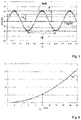
- the figure 5 shows an exemplary section of the time course of the speed fluctuation in a flowing fluid at an average speed of 10m/s and an assumed sinusoidal speed fluctuation, which can be characterized by statistical variables such as amplitude, standard deviation ⁇ , mean value v M , dp M and frequency f.
- the degree of turbulence can be determined from, for example, the standard deviation ⁇ and the mean flow velocity v M .
- the variance or the standard deviation ⁇ of the fluctuations are particularly suitable for evaluating the reference value fluctuations (see figures 5 and 7 ), the amplitude A or the frequency f of the reference value fluctuations.
- the influencing variables can be integrated via characteristic diagrams that have been determined experimentally, for example.
- the absolute flow rate can then result, for example, from a correlation of statistical or numerical variables based on the reference value fluctuation with the flow rate.
- figure 8 shows the correlation between the fluctuation value and the mean face velocity;
- the fluctuation value here is an example of the standard deviation determined from a series of dp(t) measured values.
- a correlation of statistical or numerical variables W (for example the standard deviation ⁇ , the variance, etc.) on the basis of the reference value fluctuations with the flow rate is illustrated as an example for an effective pressure sensor signal.
- the offset of a differential pressure sensor can also be determined and corrected.
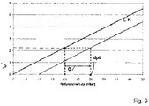
- figure 9 shows how, based on a reference value fluctuation, a reference value assigned via a characteristic curve is determined and compared to the measured (average) reference value. The difference then is the offset.
Landscapes
- Physics & Mathematics (AREA)
- Fluid Mechanics (AREA)
- General Physics & Mathematics (AREA)
- Electromagnetism (AREA)
- Measuring Volume Flow (AREA)
Claims (11)
- Procédé, destiné à déterminer une vitesse d'écoulement (VM) absolue d'un débit volumétrique ou d'un débit massique, comprenant les étapes de procédé suivantes, consistant à :mesurer des valeurs de référence (dpi, fi, li, Pi, ti, Ui, Vi) continues dans un tube de mesure (1) disposant d'un tronçon (3) rétréci, d'un premier capteur de pression (4') placé dans un tronçon de tube (2) non rétréci du tube de mesure (1) et d'un deuxième capteur de pression (4") placé dans le tronçon (3) rétréci du tube de mesure (1),déterminer des fluctuations des valeurs de référence,calculer ou reproduire la vitesse d'écoulement (VM) en dépendance d'une fonction d'évaluation numérique et/ou statistique des fluctuations des valeurs de référence, notamment d'une valeur de fluctuation (W) générée à partir de celle-ci, comme l'amplitude (A), l'écart standard (σ), la variance des fluctuations des valeurs de référence,en tant que valeurs de référence étant utilisées des valeurs de mesure dont chaque valeur individuelle se trouve dans une corrélation physique directe avec la vitesse d'écoulement,la présence d'un écoulement étant vérifiée à l'aide d'une comparaison de la fluctuation des valeurs de référence avec une valeur limite et dans le cas où aucun écoulement n'est présent, une dérive de décalage qui se produit étant corrigée par un relevé de mesures renouvelé de la valeur des capteurs de la dérive actuelle.
- Procédé selon la revendication 1, caractérisé en ce que l'on utilise en tant que valeurs de référence des valeurs de vitesse (Vi) et en ce que les fluctuations des valeurs de référence sont créées par des fluctuations desdites valeurs de vitesse (Vi).
- Procédé selon l'une quelconque des revendications précédentes, caractérisé en ce que l'on détermine la vitesse d'écoulement (VM) absolue en dépendance de la variance des fluctuations des valeurs de référence.
- Procédé selon l'une quelconque des revendications précédentes, caractérisé en ce que la vitesse d'écoulement (VM) absolue en dépendance de l'écart standard des fluctuations des valeurs de référence.
- Procédé selon l'une quelconque des revendications précédentes, caractérisé en ce l'on détermine une amplitude des fluctuations des valeurs de référence (dpi, fi, li, Pi, ti, Ui, Vi), et en ce que l'on calcule la vitesse d'écoulement (VM) absolue en dépendance de l'amplitude des fluctuations des valeurs de référence.
- Procédé selon l'une quelconque des revendications précédentes, caractérisé en ce que l'on détermine la vitesse d'écoulement (VM) absolue en dépendance de la fréquence (fi, 1/Ti) des fluctuations des valeurs de référence.
- Procédé selon l'une quelconque des revendications précédentes, caractérisé en ce que le calcul de la vitesse d'écoulement (VM) absolue s'effectue par ailleurs en dépendance d'une valeur de référence (dpM, fm, IM, PM, tM, UM, Vm) moyenne.
- Procédé selon la revendication précédente, caractérisé en ce que des paramètres de calcul destinés à déterminer la vitesse d'écoulement (VM) absolue comprennent le degré de turbulence de l'écoulement.
- Procédé, destiné à déterminer une vitesse d'écoulement (VM) absolue d'un débit volumétrique, la vitesse d'écoulement (VM) absolue étant déterminée par un procédé selon l'une quelconque des revendications précédentes, dans le cas où des valeurs de référence (dpi, fi, li, Pi, ti, Ui, Vi) sont inférieures à une valeur limite définie, et la vitesse d'écoulement (VM) absolue étant déterminée sans évaluation numérique ou statistique des fluctuations des valeurs de référence, dans le cas où des valeurs de référence (dpi, fi, li, Pi, ti, Ui, Vi) sont supérieures à la valeur limite définie.
- Procédé selon l'une quelconque des revendications précédentes, caractérisé en ce qu'avant la mesure continue, l'on procède à un étalonnage, des fluctuations des valeurs de référence à vitesse d'écoulement élevée, notamment en présence d'une valeur de référence supérieure à une valeur limite définie étant déterminées, les fluctuations des valeurs de référence étant affectées à une vitesse d'écoulement (VM) absolue et par la suite, des paramètres de calcul étant adaptés.
- Ensemble de mesure, lequel est aménagé pour réaliser un procédé selon l'une quelconque des revendications précédentes, comprenant un tube de mesure (1) disposant d'un tronçon (3) rétréci, un premier capteur de pression (4') placé dans un tronçon de tube (2) non rétréci du tube de mesure (1), un deuxième capteur de pression (4") placé dans le tronçon (3) rétréci du tube de mesure (1) et une unité de traitement des données.
Applications Claiming Priority (1)
| Application Number | Priority Date | Filing Date | Title |
|---|---|---|---|
| DE102011115708A DE102011115708A1 (de) | 2011-10-12 | 2011-10-12 | Verfahren zum Ermitteln einer absoluten Strömungsgeschwindigkeit eines Volumen- oder Massenstroms |
Publications (2)
| Publication Number | Publication Date |
|---|---|
| EP2581714A1 EP2581714A1 (fr) | 2013-04-17 |
| EP2581714B1 true EP2581714B1 (fr) | 2022-12-07 |
Family
ID=47263028
Family Applications (1)
| Application Number | Title | Priority Date | Filing Date |
|---|---|---|---|
| EP12187952.2A Active EP2581714B1 (fr) | 2011-10-12 | 2012-10-10 | Procédé et dispositif de détermination d'une vitesse d'écoulement absolue d'un flux massique ou volumique |
Country Status (3)
| Country | Link |
|---|---|
| US (1) | US9488509B2 (fr) |
| EP (1) | EP2581714B1 (fr) |
| DE (1) | DE102011115708A1 (fr) |
Families Citing this family (3)
| Publication number | Priority date | Publication date | Assignee | Title |
|---|---|---|---|---|
| CN110926570B (zh) * | 2018-09-20 | 2021-01-01 | 中国石油天然气股份有限公司 | 对临界流文丘里喷嘴进行校准的方法和装置 |
| US11220967B1 (en) | 2020-10-06 | 2022-01-11 | Garrett Transportation I, Inc. | Mass flow measurement system using adaptive calibration and sensor diagnostics |
| CN115046614B (zh) * | 2022-05-17 | 2024-10-15 | 中国航空工业集团公司哈尔滨空气动力研究所 | 一种进气道试验低压空气文丘里流量计实况校准方法 |
Citations (3)
| Publication number | Priority date | Publication date | Assignee | Title |
|---|---|---|---|---|
| DE3523888A1 (de) * | 1985-07-04 | 1987-01-08 | Battelle Institut E V | Verfahren und vorrichtung zur kontinuierlichen bestimmung der ausbreitungsgeschwindigkeit von stroemenden gasen oder fluessigkeiten |
| US20100011869A1 (en) * | 2007-07-20 | 2010-01-21 | Rosemount Inc. | Differential pressure diagnostic for process fluid pulsations |
| DE102009001525A1 (de) * | 2009-03-12 | 2010-09-16 | Endress + Hauser Flowtec Ag | Verfahren und Wirbelströmungsmessgerät zum Überwachen und/oder Messen einer Wandströmung eines in einer Rohrleitung strömenden, zwei- oder mehrphasigen Mediums |
Family Cites Families (13)
| Publication number | Priority date | Publication date | Assignee | Title |
|---|---|---|---|---|
| US3908761A (en) | 1973-05-02 | 1975-09-30 | Shell Oil Co | Method for determining liquid production from a well |
| US4596133A (en) * | 1983-07-29 | 1986-06-24 | Panametrics, Inc. | Apparatus and methods for measuring fluid flow parameters |
| US4787252A (en) | 1987-09-30 | 1988-11-29 | Panametrics, Inc. | Differential correlation analyzer |
| US5373026A (en) | 1992-12-15 | 1994-12-13 | The Dow Chemical Company | Methods of insulating with plastic structures containing thermal grade carbon black |
| US5673026A (en) * | 1994-06-14 | 1997-09-30 | Texaco Inc. | Stopped flow detection using statistical methods |
| US5741980A (en) | 1994-11-02 | 1998-04-21 | Foster-Miller, Inc. | Flow analysis system and method |
| JP3510378B2 (ja) * | 1995-03-30 | 2004-03-29 | 東京瓦斯株式会社 | ガス流量計 |
| US5864183A (en) * | 1996-08-28 | 1999-01-26 | Voith Hydro, Inc. | Method and apparatus for optimizing performance of a pump-turbine |
| US6170338B1 (en) | 1997-03-27 | 2001-01-09 | Rosemont Inc. | Vortex flowmeter with signal processing |
| US6412352B1 (en) | 1999-03-24 | 2002-07-02 | Bechtel Bwxt Idaho, Llc | Method and apparatus for measuring the mass flow rate of a fluid |
| KR100487690B1 (ko) * | 1999-06-24 | 2005-05-06 | 마쯔시다덴기산교 가부시키가이샤 | 유량계 |
| WO2003077757A1 (fr) * | 2002-03-12 | 2003-09-25 | The Regents Of The University Of California | Vitesse de flux transversal d'imagerie au moyen de largeur de bande de la tomographie de doppler optique resolue en phase de deplacement de frequence doppler |
| US20130006130A1 (en) * | 2009-12-28 | 2013-01-03 | Gambro Lundia Ab | Device and method for monitoring a fluid flow rate in a cardiovascular system |
-
2011
- 2011-10-12 DE DE102011115708A patent/DE102011115708A1/de active Pending
-
2012
- 2012-10-10 EP EP12187952.2A patent/EP2581714B1/fr active Active
- 2012-10-12 US US13/650,826 patent/US9488509B2/en active Active
Patent Citations (3)
| Publication number | Priority date | Publication date | Assignee | Title |
|---|---|---|---|---|
| DE3523888A1 (de) * | 1985-07-04 | 1987-01-08 | Battelle Institut E V | Verfahren und vorrichtung zur kontinuierlichen bestimmung der ausbreitungsgeschwindigkeit von stroemenden gasen oder fluessigkeiten |
| US20100011869A1 (en) * | 2007-07-20 | 2010-01-21 | Rosemount Inc. | Differential pressure diagnostic for process fluid pulsations |
| DE102009001525A1 (de) * | 2009-03-12 | 2010-09-16 | Endress + Hauser Flowtec Ag | Verfahren und Wirbelströmungsmessgerät zum Überwachen und/oder Messen einer Wandströmung eines in einer Rohrleitung strömenden, zwei- oder mehrphasigen Mediums |
Also Published As
| Publication number | Publication date |
|---|---|
| US20130096850A1 (en) | 2013-04-18 |
| US9488509B2 (en) | 2016-11-08 |
| DE102011115708A1 (de) | 2013-04-18 |
| EP2581714A1 (fr) | 2013-04-17 |
Similar Documents
| Publication | Publication Date | Title |
|---|---|---|
| EP2406585B1 (fr) | Procédé et appareil de mesure d'écoulement tourbillonnaire, destinés à surveiller et/ou mesurer un écoulement pariétal d'un fluide traversant une conduite tubulaire et possédant deux phases ou plus | |
| EP3428583B1 (fr) | Procédé de fonctionnement d'un compteur de fluide et compteur de fluide | |
| EP2513612B1 (fr) | Procédé pour faire fonctionner un débitmètre massique coriolis ainsi que débitmètre massique coriolis | |
| DE10254053B4 (de) | Verfahren und Vorrichtung zur Bestimmung und/oder Überwachung eines Volumen- und/oder Massenstroms | |
| EP3325923B1 (fr) | Débitmètre selon le principe de comptage de tourbillons | |
| EP0046965A1 (fr) | Procédé et appareil pour la détermination dynamique du débit massique independant de la densité | |
| EP2786107A2 (fr) | Procédé de calorimétrie au moyen d'un débitmètre à ultrasons | |
| DE2512644A1 (de) | Vorrichtung zur messung des durchflusses und/oder viskositaet von fluiden | |
| DE102012109237A1 (de) | Durchflussmessgerät, sowie Verwendung dieses Durchflussgerätes und Verfahren zur Ermittlung der Fließgeschwindigkeit | |
| EP2572169A1 (fr) | Procédé permettant de déterminer le débit d'un milieu passant à travers un tube de mesure | |
| DE102012220505B4 (de) | Überwachung eines Kondensatableiters | |
| EP2581714B1 (fr) | Procédé et dispositif de détermination d'une vitesse d'écoulement absolue d'un flux massique ou volumique | |
| DE102007053105B4 (de) | Verfahren und Vorrichtung zur Volumenstrommessung von Fluiden in Rohrleitungen | |
| DE102005059062A1 (de) | Vorrichtung zur Bestimmung eines Massenstroms | |
| EP2715293B1 (fr) | Dispositif de mesure avec capteur thermique pour mesurer le débit d'un fluide | |
| DE102011050716B4 (de) | Verfahren und Vorrichtung zur Online-Messung der Viskosität eines Fluids | |
| DE102014205040A1 (de) | Durchflussmesser und Verfahren für einen Durchflussmesser | |
| DE102020131298A1 (de) | Verfahren zur Durchfluss- und/oder Mengenmessung in einer fluidführenden Rohrleitung mit stark schwankenden Durchflussmengen sowie eine Anordnung zur Durchführung des Verfahrens | |
| DE102012109234A1 (de) | Durchflussmessgerät, sowie Verwendung dieses Durchflussgerätes und Verfahren zur Ermittlung der Fließgeschwindigkeit | |
| DE102014208277A1 (de) | Sensor und Verfahren zum Erfassen zumindest einer messbaren Messgröße eines Mediums in einem Rohr | |
| EP1731883B1 (fr) | Procédé pour détecter un changement géométrique d'un canal de mesure de débit par ultrasons | |
| DE102010014693B3 (de) | Fluid-Durchflussmesssystem, Kalibriervorrichtung für ein Fluid-Durchflussmesssystem und Verfahren zum Kalibrieren eines Durchflussmessgerätes | |
| WO2021110434A1 (fr) | Procédé de détermination et/ou de surveillance d'au moins une propriété rhéologique d'un milieu | |
| EP1512948A1 (fr) | Débitmètre pour gaz avec un diagnostic d'écoulement | |
| EP4521072B1 (fr) | Transmetteur de pression active pour mesurer des courants de fluides gazeux et liquides et procédé correspondant |
Legal Events
| Date | Code | Title | Description |
|---|---|---|---|
| PUAI | Public reference made under article 153(3) epc to a published international application that has entered the european phase |
Free format text: ORIGINAL CODE: 0009012 |
|
| AK | Designated contracting states |
Kind code of ref document: A1 Designated state(s): AL AT BE BG CH CY CZ DE DK EE ES FI FR GB GR HR HU IE IS IT LI LT LU LV MC MK MT NL NO PL PT RO RS SE SI SK SM TR |
|
| AX | Request for extension of the european patent |
Extension state: BA ME |
|
| 17P | Request for examination filed |
Effective date: 20131017 |
|
| RBV | Designated contracting states (corrected) |
Designated state(s): AL AT BE BG CH CY CZ DE DK EE ES FI FR GB GR HR HU IE IS IT LI LT LU LV MC MK MT NL NO PL PT RO RS SE SI SK SM TR |
|
| 17Q | First examination report despatched |
Effective date: 20151211 |
|
| STAA | Information on the status of an ep patent application or granted ep patent |
Free format text: STATUS: EXAMINATION IS IN PROGRESS |
|
| REG | Reference to a national code |
Ref country code: DE Ref legal event code: R079 Ref document number: 502012017112 Country of ref document: DE Free format text: PREVIOUS MAIN CLASS: G01F0001380000 Ipc: G01F0001440000 |
|
| RIC1 | Information provided on ipc code assigned before grant |
Ipc: G01F 25/10 20220101ALI20220321BHEP Ipc: G01F 15/02 20060101ALI20220321BHEP Ipc: G01F 1/38 20060101ALI20220321BHEP Ipc: G01F 1/50 20060101ALI20220321BHEP Ipc: G01F 1/44 20060101AFI20220321BHEP |
|
| GRAP | Despatch of communication of intention to grant a patent |
Free format text: ORIGINAL CODE: EPIDOSNIGR1 |
|
| STAA | Information on the status of an ep patent application or granted ep patent |
Free format text: STATUS: GRANT OF PATENT IS INTENDED |
|
| INTG | Intention to grant announced |
Effective date: 20220523 |
|
| RAP1 | Party data changed (applicant data changed or rights of an application transferred) |
Owner name: SYSTEC AUTOMOTIVE GMBH |
|
| GRAS | Grant fee paid |
Free format text: ORIGINAL CODE: EPIDOSNIGR3 |
|
| GRAA | (expected) grant |
Free format text: ORIGINAL CODE: 0009210 |
|
| STAA | Information on the status of an ep patent application or granted ep patent |
Free format text: STATUS: THE PATENT HAS BEEN GRANTED |
|
| AK | Designated contracting states |
Kind code of ref document: B1 Designated state(s): AL AT BE BG CH CY CZ DE DK EE ES FI FR GB GR HR HU IE IS IT LI LT LU LV MC MK MT NL NO PL PT RO RS SE SI SK SM TR |
|
| REG | Reference to a national code |
Ref country code: GB Ref legal event code: FG4D Free format text: NOT ENGLISH |
|
| REG | Reference to a national code |
Ref country code: CH Ref legal event code: EP Ref country code: AT Ref legal event code: REF Ref document number: 1536559 Country of ref document: AT Kind code of ref document: T Effective date: 20221215 |
|
| REG | Reference to a national code |
Ref country code: DE Ref legal event code: R096 Ref document number: 502012017112 Country of ref document: DE |
|
| REG | Reference to a national code |
Ref country code: IE Ref legal event code: FG4D Free format text: LANGUAGE OF EP DOCUMENT: GERMAN |
|
| REG | Reference to a national code |
Ref country code: LT Ref legal event code: MG9D |
|
| REG | Reference to a national code |
Ref country code: NL Ref legal event code: MP Effective date: 20221207 |
|
| PG25 | Lapsed in a contracting state [announced via postgrant information from national office to epo] |
Ref country code: SE Free format text: LAPSE BECAUSE OF FAILURE TO SUBMIT A TRANSLATION OF THE DESCRIPTION OR TO PAY THE FEE WITHIN THE PRESCRIBED TIME-LIMIT Effective date: 20221207 Ref country code: NO Free format text: LAPSE BECAUSE OF FAILURE TO SUBMIT A TRANSLATION OF THE DESCRIPTION OR TO PAY THE FEE WITHIN THE PRESCRIBED TIME-LIMIT Effective date: 20230307 Ref country code: LT Free format text: LAPSE BECAUSE OF FAILURE TO SUBMIT A TRANSLATION OF THE DESCRIPTION OR TO PAY THE FEE WITHIN THE PRESCRIBED TIME-LIMIT Effective date: 20221207 Ref country code: FI Free format text: LAPSE BECAUSE OF FAILURE TO SUBMIT A TRANSLATION OF THE DESCRIPTION OR TO PAY THE FEE WITHIN THE PRESCRIBED TIME-LIMIT Effective date: 20221207 Ref country code: ES Free format text: LAPSE BECAUSE OF FAILURE TO SUBMIT A TRANSLATION OF THE DESCRIPTION OR TO PAY THE FEE WITHIN THE PRESCRIBED TIME-LIMIT Effective date: 20221207 |
|
| PG25 | Lapsed in a contracting state [announced via postgrant information from national office to epo] |
Ref country code: RS Free format text: LAPSE BECAUSE OF FAILURE TO SUBMIT A TRANSLATION OF THE DESCRIPTION OR TO PAY THE FEE WITHIN THE PRESCRIBED TIME-LIMIT Effective date: 20221207 Ref country code: PL Free format text: LAPSE BECAUSE OF FAILURE TO SUBMIT A TRANSLATION OF THE DESCRIPTION OR TO PAY THE FEE WITHIN THE PRESCRIBED TIME-LIMIT Effective date: 20221207 Ref country code: LV Free format text: LAPSE BECAUSE OF FAILURE TO SUBMIT A TRANSLATION OF THE DESCRIPTION OR TO PAY THE FEE WITHIN THE PRESCRIBED TIME-LIMIT Effective date: 20221207 Ref country code: HR Free format text: LAPSE BECAUSE OF FAILURE TO SUBMIT A TRANSLATION OF THE DESCRIPTION OR TO PAY THE FEE WITHIN THE PRESCRIBED TIME-LIMIT Effective date: 20221207 Ref country code: GR Free format text: LAPSE BECAUSE OF FAILURE TO SUBMIT A TRANSLATION OF THE DESCRIPTION OR TO PAY THE FEE WITHIN THE PRESCRIBED TIME-LIMIT Effective date: 20230308 |
|
| PG25 | Lapsed in a contracting state [announced via postgrant information from national office to epo] |
Ref country code: NL Free format text: LAPSE BECAUSE OF FAILURE TO SUBMIT A TRANSLATION OF THE DESCRIPTION OR TO PAY THE FEE WITHIN THE PRESCRIBED TIME-LIMIT Effective date: 20221207 |
|
| PG25 | Lapsed in a contracting state [announced via postgrant information from national office to epo] |
Ref country code: SM Free format text: LAPSE BECAUSE OF FAILURE TO SUBMIT A TRANSLATION OF THE DESCRIPTION OR TO PAY THE FEE WITHIN THE PRESCRIBED TIME-LIMIT Effective date: 20221207 Ref country code: RO Free format text: LAPSE BECAUSE OF FAILURE TO SUBMIT A TRANSLATION OF THE DESCRIPTION OR TO PAY THE FEE WITHIN THE PRESCRIBED TIME-LIMIT Effective date: 20221207 Ref country code: PT Free format text: LAPSE BECAUSE OF FAILURE TO SUBMIT A TRANSLATION OF THE DESCRIPTION OR TO PAY THE FEE WITHIN THE PRESCRIBED TIME-LIMIT Effective date: 20230410 Ref country code: EE Free format text: LAPSE BECAUSE OF FAILURE TO SUBMIT A TRANSLATION OF THE DESCRIPTION OR TO PAY THE FEE WITHIN THE PRESCRIBED TIME-LIMIT Effective date: 20221207 Ref country code: CZ Free format text: LAPSE BECAUSE OF FAILURE TO SUBMIT A TRANSLATION OF THE DESCRIPTION OR TO PAY THE FEE WITHIN THE PRESCRIBED TIME-LIMIT Effective date: 20221207 |
|
| PG25 | Lapsed in a contracting state [announced via postgrant information from national office to epo] |
Ref country code: SK Free format text: LAPSE BECAUSE OF FAILURE TO SUBMIT A TRANSLATION OF THE DESCRIPTION OR TO PAY THE FEE WITHIN THE PRESCRIBED TIME-LIMIT Effective date: 20221207 Ref country code: IS Free format text: LAPSE BECAUSE OF FAILURE TO SUBMIT A TRANSLATION OF THE DESCRIPTION OR TO PAY THE FEE WITHIN THE PRESCRIBED TIME-LIMIT Effective date: 20230407 Ref country code: AL Free format text: LAPSE BECAUSE OF FAILURE TO SUBMIT A TRANSLATION OF THE DESCRIPTION OR TO PAY THE FEE WITHIN THE PRESCRIBED TIME-LIMIT Effective date: 20221207 |
|
| REG | Reference to a national code |
Ref country code: DE Ref legal event code: R097 Ref document number: 502012017112 Country of ref document: DE |
|
| PLBE | No opposition filed within time limit |
Free format text: ORIGINAL CODE: 0009261 |
|
| STAA | Information on the status of an ep patent application or granted ep patent |
Free format text: STATUS: NO OPPOSITION FILED WITHIN TIME LIMIT |
|
| PG25 | Lapsed in a contracting state [announced via postgrant information from national office to epo] |
Ref country code: DK Free format text: LAPSE BECAUSE OF FAILURE TO SUBMIT A TRANSLATION OF THE DESCRIPTION OR TO PAY THE FEE WITHIN THE PRESCRIBED TIME-LIMIT Effective date: 20221207 |
|
| 26N | No opposition filed |
Effective date: 20230908 |
|
| PG25 | Lapsed in a contracting state [announced via postgrant information from national office to epo] |
Ref country code: SI Free format text: LAPSE BECAUSE OF FAILURE TO SUBMIT A TRANSLATION OF THE DESCRIPTION OR TO PAY THE FEE WITHIN THE PRESCRIBED TIME-LIMIT Effective date: 20221207 |
|
| P01 | Opt-out of the competence of the unified patent court (upc) registered |
Effective date: 20231229 |
|
| PG25 | Lapsed in a contracting state [announced via postgrant information from national office to epo] |
Ref country code: IT Free format text: LAPSE BECAUSE OF FAILURE TO SUBMIT A TRANSLATION OF THE DESCRIPTION OR TO PAY THE FEE WITHIN THE PRESCRIBED TIME-LIMIT Effective date: 20221207 Ref country code: MC Free format text: LAPSE BECAUSE OF FAILURE TO SUBMIT A TRANSLATION OF THE DESCRIPTION OR TO PAY THE FEE WITHIN THE PRESCRIBED TIME-LIMIT Effective date: 20221207 |
|
| REG | Reference to a national code |
Ref country code: CH Ref legal event code: PL |
|
| REG | Reference to a national code |
Ref country code: BE Ref legal event code: MM Effective date: 20231031 |
|
| PG25 | Lapsed in a contracting state [announced via postgrant information from national office to epo] |
Ref country code: LU Free format text: LAPSE BECAUSE OF NON-PAYMENT OF DUE FEES Effective date: 20231010 |
|
| GBPC | Gb: european patent ceased through non-payment of renewal fee |
Effective date: 20231010 |
|
| PG25 | Lapsed in a contracting state [announced via postgrant information from national office to epo] |
Ref country code: LU Free format text: LAPSE BECAUSE OF NON-PAYMENT OF DUE FEES Effective date: 20231010 |
|
| PG25 | Lapsed in a contracting state [announced via postgrant information from national office to epo] |
Ref country code: GB Free format text: LAPSE BECAUSE OF NON-PAYMENT OF DUE FEES Effective date: 20231010 |
|
| PG25 | Lapsed in a contracting state [announced via postgrant information from national office to epo] |
Ref country code: CH Free format text: LAPSE BECAUSE OF NON-PAYMENT OF DUE FEES Effective date: 20231031 |
|
| PG25 | Lapsed in a contracting state [announced via postgrant information from national office to epo] |
Ref country code: GB Free format text: LAPSE BECAUSE OF NON-PAYMENT OF DUE FEES Effective date: 20231010 Ref country code: FR Free format text: LAPSE BECAUSE OF NON-PAYMENT OF DUE FEES Effective date: 20231031 Ref country code: CH Free format text: LAPSE BECAUSE OF NON-PAYMENT OF DUE FEES Effective date: 20231031 |
|
| PG25 | Lapsed in a contracting state [announced via postgrant information from national office to epo] |
Ref country code: BE Free format text: LAPSE BECAUSE OF NON-PAYMENT OF DUE FEES Effective date: 20231031 |
|
| PG25 | Lapsed in a contracting state [announced via postgrant information from national office to epo] |
Ref country code: IE Free format text: LAPSE BECAUSE OF NON-PAYMENT OF DUE FEES Effective date: 20231010 |
|
| PG25 | Lapsed in a contracting state [announced via postgrant information from national office to epo] |
Ref country code: IE Free format text: LAPSE BECAUSE OF NON-PAYMENT OF DUE FEES Effective date: 20231010 |
|
| PG25 | Lapsed in a contracting state [announced via postgrant information from national office to epo] |
Ref country code: BG Free format text: LAPSE BECAUSE OF FAILURE TO SUBMIT A TRANSLATION OF THE DESCRIPTION OR TO PAY THE FEE WITHIN THE PRESCRIBED TIME-LIMIT Effective date: 20221207 |
|
| PG25 | Lapsed in a contracting state [announced via postgrant information from national office to epo] |
Ref country code: BG Free format text: LAPSE BECAUSE OF FAILURE TO SUBMIT A TRANSLATION OF THE DESCRIPTION OR TO PAY THE FEE WITHIN THE PRESCRIBED TIME-LIMIT Effective date: 20221207 |
|
| REG | Reference to a national code |
Ref country code: AT Ref legal event code: MM01 Ref document number: 1536559 Country of ref document: AT Kind code of ref document: T Effective date: 20231010 |
|
| PG25 | Lapsed in a contracting state [announced via postgrant information from national office to epo] |
Ref country code: AT Free format text: LAPSE BECAUSE OF NON-PAYMENT OF DUE FEES Effective date: 20231010 |
|
| PG25 | Lapsed in a contracting state [announced via postgrant information from national office to epo] |
Ref country code: AT Free format text: LAPSE BECAUSE OF NON-PAYMENT OF DUE FEES Effective date: 20231010 |
|
| PG25 | Lapsed in a contracting state [announced via postgrant information from national office to epo] |
Ref country code: CY Free format text: LAPSE BECAUSE OF FAILURE TO SUBMIT A TRANSLATION OF THE DESCRIPTION OR TO PAY THE FEE WITHIN THE PRESCRIBED TIME-LIMIT; INVALID AB INITIO Effective date: 20121010 |
|
| PG25 | Lapsed in a contracting state [announced via postgrant information from national office to epo] |
Ref country code: HU Free format text: LAPSE BECAUSE OF FAILURE TO SUBMIT A TRANSLATION OF THE DESCRIPTION OR TO PAY THE FEE WITHIN THE PRESCRIBED TIME-LIMIT; INVALID AB INITIO Effective date: 20121010 |
|
| PG25 | Lapsed in a contracting state [announced via postgrant information from national office to epo] |
Ref country code: TR Free format text: LAPSE BECAUSE OF FAILURE TO SUBMIT A TRANSLATION OF THE DESCRIPTION OR TO PAY THE FEE WITHIN THE PRESCRIBED TIME-LIMIT Effective date: 20221207 |
|
| PGFP | Annual fee paid to national office [announced via postgrant information from national office to epo] |
Ref country code: DE Payment date: 20251020 Year of fee payment: 14 |