EP2581725A2 - Verfahren und Systeme für die automatische Rollelement-Lagerfehlererfassung - Google Patents
Verfahren und Systeme für die automatische Rollelement-Lagerfehlererfassung Download PDFInfo
- Publication number
- EP2581725A2 EP2581725A2 EP12188051.2A EP12188051A EP2581725A2 EP 2581725 A2 EP2581725 A2 EP 2581725A2 EP 12188051 A EP12188051 A EP 12188051A EP 2581725 A2 EP2581725 A2 EP 2581725A2
- Authority
- EP
- European Patent Office
- Prior art keywords
- vibration signal
- bearing
- processor
- digital vibration
- signal
- Prior art date
- Legal status (The legal status is an assumption and is not a legal conclusion. Google has not performed a legal analysis and makes no representation as to the accuracy of the status listed.)
- Withdrawn
Links
Images


Classifications
-
- G—PHYSICS
- G01—MEASURING; TESTING
- G01M—TESTING STATIC OR DYNAMIC BALANCE OF MACHINES OR STRUCTURES; TESTING OF STRUCTURES OR APPARATUS, NOT OTHERWISE PROVIDED FOR
- G01M13/00—Testing of machine parts
- G01M13/04—Bearings
- G01M13/045—Acoustic or vibration analysis
Definitions
- the present application relates generally to rotating machines and, more particularly, to methods and systems for use in detecting rolling-element bearing faults in a rotating machine.
- At least some known power generation systems such as wind turbines, include a generator that supplies electrical power to an electrical grid or to another power distribution system. Such generators are driven by a rotating drive shaft that is supported by bearings. A bearing monitoring system is sometimes used to monitor the bearings and/or other rotating elements.
- At least some known bearing monitoring systems execute an enveloping algorithm on an incoming signal, such as a vibration signal. More specifically, such algorithms enable identification of particular frequencies within the incoming signal that may suggest a bearing fault. The particular frequencies that suggest a bearing fault vary depending on the bearing, the power generation system, and other factors. Therefore, at least some known bearing monitoring systems are generally only capable of detecting bearing faults that produce expected frequencies. Thus, a bearing monitoring system may ignore some frequencies that may be indicative of bearing faults simply because the bearing monitoring system is not configured to examine such frequencies. Accordingly, systems are needed which automatically detect bearing faults without reference to frequencies of known bearing defects.
- a monitoring system includes at least one sensor configured to detect a frequency of at least one rotating component being monitored.
- the monitoring system also includes a processor programmed to receive, from the at least one sensor, a sensor signal that includes at least one frequency indicative of a predetermined condition, convert the sensor signal to a digital vibration signal, generate an envelope spectrum from the digital vibration signal, and detect a bearing fault based on a fundamental frequency of the envelope spectrum and a first detection threshold.
- a bearing monitoring system includes a processor programmed to receive, from at least one sensor, a sensor signal that includes at least one frequency indicative of a predetermined condition, convert the sensor signal to a digital vibration signal, generate an envelope spectrum from the digital vibration signal, and detect a bearing fault based on a fundamental frequency of the envelope spectrum and a first detection threshold.
- a method of monitoring a rotating machine includes receiving, from at least one sensor monitoring the machine, a sensor signal that includes at least one frequency indicative of a predetermined condition, converting the sensor signal to a digital vibration signal, generating an envelope spectrum from the digital vibration signal, and detecting a bearing fault in the machine based on a fundamental frequency of the envelope spectrum and a first detection threshold.
- FIG. 1 illustrates an exemplary bearing monitoring system 100 that may be used to monitor a rotating machine 101.
- machine 101 is a variable speed machine, such as a wind turbine, a hydroelectric generator, and/or any other rotating machine that operates with a variable speed.
- machine 101 may be a synchronous speed machine.
- machine 101 drives a drive shaft 102 that is coupled to a load 104.
- Drive shaft 102 is at least partially supported by one or more bearings 106 housed within a support structure 108, such as a gearbox.
- bearings 106 may be housed within load 104, and/or within any suitable structure that enables bearings 106 to support drive shaft 102.
- bearings 106 are maintained in rotational contact with drive shaft 102 and support structure 108. If one or more bearings 106 develops a crack, spall, or any other defect, each of those bearings 106 may oscillate or "ring" (hereinafter referred to as a "ring event") at a natural frequency of support structure 108 when the area of the defect on the bearing 106 contacts drive shaft 102 and/or support structure 108 during rotation of drive shaft 102. Generally, one or more ring events occur at a frequency that is proportional to a rotational speed of machine 101.
- Ring events generally induce vibrations into support structure 108 and/or bearings 106.
- One or more vibration sensors 110 such as accelerometers, detect and measure the ring event vibrations and transmit a signal representative of the vibration measurements to a signal processing system 114 for processing and/or analysis.
- signal processing system 114 is a bearing analysis system, and more specifically, each vibration sensor 110 transmits a signal, such as a vibration signal, to signal processing system 114.
- the vibration signal includes a plurality of frequency components, such as, without limitation, one or more shaft vibration frequencies, and/or one or more noise frequencies.
- the vibration signal may include one or more frequencies, such as one or more bearing defect frequencies.
- a speed sensor 112 measures a rotational speed of drive shaft 102 and transmits one or more signals indicative of the speed measurements to bearing analysis system 114 for processing and/or analysis.
- speed sensor 112 may measure a rotational speed of drive shaft 102 at a plurality of different times during each revolution of drive shaft 102. More specifically, in the exemplary embodiment, speed sensor 112 is an angular encoder that produces an event, or an encoder signal, at substantially equally angularly-spaced positions of drive shaft 102. Alternatively, speed sensor 112 may be an optical sensor that detects a once-per-turn mark on drive shaft 102. Such events or marks may be used to determine a rotational speed of drive shaft 102. Moreover, in the exemplary embodiment, measurements from vibration sensor 110 and/or any other suitable sensor are acquired, or sampled, synchronously with respect to the events.
- FIG. 2 is a block diagram of an exemplary bearing analysis system 114 that may be used to analyze an operation of machine 101 (shown in FIG. 1 ).
- system 114 includes a processor 202, a display 204, a memory 206, a human interface device 207, and a communication interface 208.
- Display 204, memory 206, and communication interface 208 are each coupled to, and are in data communication with, processor 202.
- processor 202, display 204, memory 206, and/or communication interface 208 is positioned within a remote system (not shown) that is communicatively coupled to system 114.
- Processor 202 includes any suitable programmable system including one or more systems and microcontrollers, microprocessors, reduced instruction set circuits (RISC), application specific integrated circuits (ASIC), programmable logic circuits (PLC), field programmable gate arrays (FPGA), and/or any other circuit capable of executing the functions described herein.
- RISC reduced instruction set circuits
- ASIC application specific integrated circuits
- PLC programmable logic circuits
- FPGA field programmable gate arrays
- Display 204 includes, without limitation, a liquid crystal display (LCD), a cathode ray tube (CRT), a plasma display, and/or any suitable visual output device capable of displaying graphical data and/or text to a user.
- LCD liquid crystal display
- CRT cathode ray tube
- plasma display and/or any suitable visual output device capable of displaying graphical data and/or text to a user.
- Memory 206 includes a computer readable medium, such as, without limitation, a hard disk drive, a solid state drive, a diskette, a flash drive, a compact disc, a digital video disc, random access memory (RAM), and/or any suitable storage device that enables processor 202 to store, retrieve, and/or execute instructions and/or data.
- Memory 206 may include one or more local and/or remote storage devices.
- memory 206 stores data from vibration sensor 110 and/or speed sensor 112 (both shown in FIG. 1 ), such as one or more values of a vibration signal and/or a speed signal.
- Human interface device 207 is coupled to processor 202 and receives input from a user.
- Human interface device 207 may include, for example, a keyboard, a pointing device, a mouse, a stylus, a touch sensitive panel (e.g., a touch pad or a touch screen), a gyroscope, an accelerometer, a position detector, and/or an audio input interface (e.g., including a microphone).
- Communication interface 208 may include, without limitation, a network interface controller (NIC), a network adapter, a transceiver, and/or any suitable communication device that enables system 114 to operate as described herein.
- Communication interface 208 may connect to a network (not shown) and/or to one or more data communication systems using any suitable communication protocol, such as a wired Ethernet protocol or a wireless Ethernet protocol.
- processor 202 executes instructions and/or accesses data stored in memory 206 to analyze and/or process measurements and/or signals from one or more vibration sensors 110 and/or speed sensors 112 (both shown in FIG. 1 ). Processor 202 receives the signals indicative of the sensed measurements and detects a bearing fault, as described in more detail below.
- FIG. 3 is a flow diagram of an exemplary method 300 of detecting a bearing fault by analyzing a vibration signal.
- method 300 is executed by system 114 (shown in FIG. 2 ) and/or by any other suitable system that enables a frequency to be identified as described herein.
- Instructions and/or data for method 300 are stored in a computer readable medium, such as memory 206 (shown in FIG. 2 ), and the instructions are executed by processor 202 (shown in FIG. 2 ) to perform the method 300.
- system 114 and/or processor 202 receives 301 a sensor signal having at least one frequency from at least one sensor.
- a sensor signal having at least one frequency from at least one sensor.
- an analog vibration signal from vibration sensor 110 may be received 301.
- system 114 and/or processor 202 may receive 301 any suitable signal from vibration sensor 110.
- Each signal received 301 is then converted 302 to a digital vibration signal that may be stored 304 in memory 206 for at least one revolution of machine 101 (shown in FIG. 1 ), i.e., until drive shaft 102 (shown in FIG. 1 ) has rotated through one complete revolution.
- the vibration signal is then modified 306 by enveloping or demodulating the signal using a suitable enveloping algorithm.
- the signal before the vibration signal is modified 306, the signal may be high-pass filtered, band-pass filtered, low-pass filtered, rectified, and/or smoothed during the demodulation process.
- the filtered vibration signal is modified by replacing the signed amplitude with an unsigned or direct amplitude before enveloping 306.
- the vibration signal may be analyzed 307 to detect skewness before the signal is modified 306 using any known technique. If a skewness, or the absolute value of a skewness, is above a predefined threshold, the implementation of method 300 may be aborted. For example, a skewness with an absolute value above one may indicate that electrical noise is present in the vibration signal. If the implementation of method 300 is aborted due to skewness, processor 202 may display or communicate a message indicating the cause of the abortion.
- the vibration signal is modified 306, one or more high frequency components of the original vibration signal are removed and an envelope signal, having a lower frequency than a frequency of the original vibration signal, is produced.
- the vibration signal includes one or more bearing defect frequencies
- the envelope signal includes one or more amplitude peaks that may repeat at a bearing defect repetition frequency.
- the bearing defect repetition frequency is proportional to, or approximately equal to, the rotational frequency of drive shaft 102. As drive shaft 102 may rotate at a variable speed, the bearing defect repetition frequency may vary throughout each revolution of drive shaft 102 and/or throughout the vibration signal.
- system 114 and/or processor 202 performs a transform 316 on the enveloped signal to generate an envelope spectrum.
- the transform 316 is a Fast Fourier Transform.
- the transform 316 may be any digital Fourier transform or any other transform that enables method 300 to be implemented, and to function, as described herein.
- System 114 and/or processor 202 also receives 312 one or more signals indicative of speed measurements from speed sensor 112 (shown in FIG. 1 ).
- the speed signals are converted to digital data (i.e., speed data) within system 100.
- the speed data is a predefined value based on a rotational speed of drive shaft 102 and as suggested by theory or dictated by design.
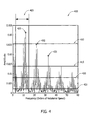
- system 114 and/or processor 202 uses the speed data to convert the envelope spectrum into orders of the speed data. For example, if the envelope spectrum were displayed on a graph, such as graph 400 shown in FIG. 4 , the Y-axis may be the amplitude of the enveloped spectrum and the X-axis may be the frequency in ascending orders of the speed data, i.e., the rotational speed of drive shaft 102.
- fault frequency range 405 may include the entire range of the vibration signal or a predetermined range that is smaller than the entire range.
- fault frequency range 405 is selected to be a frequency range that is most likely to contain rolling-element bearing fault frequencies, such as between about 2.75 * rotational speed to about 15 * rotational speed.
- system 114 and/or processor 202 calculates 317 at least one detection threshold.
- a detection threshold is calculated 317 according to the following formula: median + predefined detection factor * standard deviation.
- the predefined detection factor is preferably an integer, such as 1, 2, or 4.
- three detection thresholds are calculated 317: a first or fundamental threshold 410, a second threshold 415, and a third threshold 420, using predefined detection factors 4, 2, and 1, respectively.
- a mean may be used rather than the median.
- System 114 and/or processor 202 identifies 318 any peak that exceeds the fundamental threshold within the fault frequency range. Peaks may be identified 318 using any known technique for distinguishing and/or locating peaks or local maxima. The frequency of any peak exceeding the fundamental threshold is saved to memory 206 and is hereafter referred to as a "fundamental frequency" 425. More than one fundamental frequency 425 may be identified 318 within the fault frequency range and saved to memory 206.
- any fundamental frequency 425 is approximately (i.e., +/- 5%, +/- 10%, or +/- 25%) twice that of an electrical line frequency, that fundamental frequency 425 may be indicative of a problem with the rotor bar and not a bearing.
- the electrical line frequency is the frequency of the electrical current generated by machine 101 as measured by at least one sensor (not shown) or a predetermined value that may be stored in memory 206. If a possible rotor bar problem is detected, system 114 and/or processor 202 may report a possible rotor bar problem using display 204 or communication interface 208.
- system 114 and/or processor 202 analyzes 320 whether fundamental frequency 425 is suggestive of a bearing fault.
- the first phase of the analysis includes identifying 321 a first harmonic 430 and a second harmonic 435 of the fundamental frequency.
- the first 430 and second 435 harmonics are identified 321 by locating local spectrum lines nearest to double and triple the fundamental frequency, respectively.
- the next phase of analysis 320 includes comparing the first 430 and second 435 harmonics with the second 415 and third 420 thresholds using a test set to determine whether the vibration signal suggests a bearing fault. More specifically, the test set may include determining (a) whether the amplitude of first harmonic 430 is greater than second threshold 415, (b) whether the amplitude of first harmonic 430 is greater than a predefined peak ratio multiplied by the amplitude of fundamental frequency 425, (c) whether the amplitude of first harmonic 430 is less than the amplitude of fundamental frequency 425, (d) whether the amplitude of second harmonic 435 is greater than third threshold 420, and/or (e) whether the amplitude of second harmonic 435 is less than the amplitude of first harmonic 430.
- the predefined peak ratio is 0.5.
- a bearing fault is detected when no rotor bar problem is detected and all tests in the test set are determined to be true. Rotor bar tests are performed and bearing faults are detected for each fundamental frequency 425. If a possible bearing fault is detected among any of the fundamental frequencies 425, system 114 and/or processor 202 may report the bearing fault 322 by displaying a message using display 204 and/or by transmitting a signal using communication interface 208 indicative of a possible bearing fault. The message may include the fundamental frequency 425 of each bearing fault and/or the direct amplitude of the vibration signal or the filtered vibration signal.
- any of the predefined values and/or parameters used in implementing method 300 such as, but not limited to, the speed data, an electrical line frequency, corners for the band pass filter, the predefined skewness threshold, the fault frequency range, the predetermined detection factors and the predefined peak ratio are configurable to facilitate adjustment of method 300. More specifically, such predefined values and parameters may be input using human interface device 207 or communication interface 208, or stored in memory 206 for use by processor 202.
- System 114 facilitates automatically detecting bearing defect frequencies from rotating machines. As compared to known systems which may be limited to detecting only known defect frequencies, system 114 is capable of detecting defect frequencies without reference to known defect frequencies. Known detection systems look for a predetermined set of frequencies known to indicate a bearing fault. In contrast, system 114 acquires measurements from vibration sensor 110 and detects patterns suggestive of a bearing fault. As such, method 300 operates without any knowledge of the particular bearings in use and/or of the frequencies at which bearing faults are expected to be detected.
- system 114 may only need band pass filter corners, a skewness threshold, a fault frequency range expressed as a multiple of the rotational shaft speed, at least one detection factor, and a peak ratio in addition to the inputs of the vibration signal, rotational shaft speed and electrical line frequency.
- the above-described embodiments provide efficient and cost-effective systems and methods for use in automatically detecting a bearing fault in a rotating machine.
- the methods described herein envelope a vibration signal and apply a transform to the enveloped data in orders of rotational shaft speed.
- the methods use certain relationships among envelope spectral line amplitudes and their harmonics to detect bearing faults. As such, the methods detect a bearing fault without reference to predefined fault frequencies.
- the methods are designed to ignore false positive sources such as induction motor rotor bar passage, generator electrical noise, generator bearing fluting (EDM), and/or gearbox mesh harmonics by specifically rejecting induction motor rotor bar effects and identifying the complex patterns of spectral harmonics that are characteristic of actual bearing faults.
- Exemplary embodiments of methods and systems for automatically detecting a bearing fault in a rotating machine are described above in detail.
- the methods and systems are not limited to the specific embodiments described herein, but rather, components of the systems and/or steps of the methods may be utilized independently and separately from other components and/or steps described herein.
- the methods may also be used in combination with other measuring systems and methods, and are not limited to practice with only the rotating machine as described herein. Rather, the exemplary embodiment can be implemented and utilized in connection with many other power system applications.
Landscapes
- Physics & Mathematics (AREA)
- Acoustics & Sound (AREA)
- General Physics & Mathematics (AREA)
- Testing Of Devices, Machine Parts, Or Other Structures Thereof (AREA)
- Measurement Of Mechanical Vibrations Or Ultrasonic Waves (AREA)
Applications Claiming Priority (1)
| Application Number | Priority Date | Filing Date | Title |
|---|---|---|---|
| US13/272,978 US20130096848A1 (en) | 2011-10-13 | 2011-10-13 | Methods and systems for automatic rolling-element bearing fault detection |
Publications (1)
| Publication Number | Publication Date |
|---|---|
| EP2581725A2 true EP2581725A2 (de) | 2013-04-17 |
Family
ID=47046407
Family Applications (1)
| Application Number | Title | Priority Date | Filing Date |
|---|---|---|---|
| EP12188051.2A Withdrawn EP2581725A2 (de) | 2011-10-13 | 2012-10-10 | Verfahren und Systeme für die automatische Rollelement-Lagerfehlererfassung |
Country Status (4)
| Country | Link |
|---|---|
| US (1) | US20130096848A1 (de) |
| EP (1) | EP2581725A2 (de) |
| JP (1) | JP2013088431A (de) |
| CN (1) | CN103048132A (de) |
Cited By (26)
| Publication number | Priority date | Publication date | Assignee | Title |
|---|---|---|---|---|
| CN103728135A (zh) * | 2013-12-16 | 2014-04-16 | 西安交通大学 | 一种非负矩阵分解的轴承故障特征提取和诊断方法 |
| US20150204757A1 (en) * | 2014-01-17 | 2015-07-23 | United States Of America As Represented By The Secretary Of The Navy | Method for Implementing Rolling Element Bearing Damage Diagnosis |
| CN106053061A (zh) * | 2016-06-29 | 2016-10-26 | 潍坊学院 | 一种基于非线性模式分解和谱峭度的包络分析方法 |
| CN106053069A (zh) * | 2016-06-29 | 2016-10-26 | 潍坊学院 | 一种滚动轴承的ssd、谱峭度和平滑迭代包络分析方法 |
| CN106153338A (zh) * | 2016-06-29 | 2016-11-23 | 潍坊学院 | 一种旋转机械的elmd和有理样条平滑包络分析方法 |
| CN106153333A (zh) * | 2016-06-29 | 2016-11-23 | 潍坊学院 | 一种基于小波分解滤波的包络分析方法 |
| CN106168538A (zh) * | 2016-06-29 | 2016-11-30 | 潍坊学院 | 一种滚动轴承的itd、谱峭度和平滑迭代包络分析方法 |
| CN106198018A (zh) * | 2016-06-29 | 2016-12-07 | 潍坊学院 | 一种旋转机械的eemd和平滑迭代包络分析方法 |
| CN106198014A (zh) * | 2016-06-29 | 2016-12-07 | 潍坊学院 | 一种基于经验模式分解和谱峭度的包络分析方法 |
| CN106198011A (zh) * | 2016-06-29 | 2016-12-07 | 潍坊学院 | 一种旋转机械的elmd和三次样条平滑包络分析方法 |
| CN106198016A (zh) * | 2016-06-29 | 2016-12-07 | 潍坊学院 | 一种滚动轴承的nmd、谱峭度和平滑迭代包络分析方法 |
| CN106198013A (zh) * | 2016-06-29 | 2016-12-07 | 潍坊学院 | 一种基于经验模式分解滤波的包络分析方法 |
| CN106198012A (zh) * | 2016-06-29 | 2016-12-07 | 潍坊学院 | 一种基于局部均值分解和谱峭度的包络分析方法 |
| CN106198009A (zh) * | 2016-06-29 | 2016-12-07 | 潍坊学院 | 一种滚动轴承的emd、谱峭度和平滑迭代包络分析方法 |
| CN106198010A (zh) * | 2016-06-29 | 2016-12-07 | 潍坊学院 | 一种基于局部均值分解滤波的包络分析方法 |
| CN106198017A (zh) * | 2016-06-29 | 2016-12-07 | 潍坊学院 | 一种滚动轴承的lmd、谱峭度和平滑迭代包络分析方法 |
| CN106404396A (zh) * | 2016-08-30 | 2017-02-15 | 四川中烟工业有限责任公司 | 一种滚动轴承的故障诊断方法 |
| WO2017187333A1 (en) * | 2016-04-26 | 2017-11-02 | University Of Pretoria | A method and system for monitoring rotor blades of a turbomachine using blade tip timing (btt) |
| CN107664580A (zh) * | 2016-07-27 | 2018-02-06 | 上海王智测控技术有限公司 | 一种电动机健康状态监测仪 |
| CN108051213A (zh) * | 2018-01-12 | 2018-05-18 | 上海电力学院 | 一种滚动轴承在线故障检测方法 |
| CN106198015B (zh) * | 2016-06-29 | 2018-05-25 | 潍坊学院 | 一种滚动轴承的vmd、谱峭度和平滑迭代包络分析方法 |
| EP3421786A1 (de) * | 2017-06-02 | 2019-01-02 | General Electric Company | Systeme und verfahren zur erkennung von schäden in windturbinenlagern |
| EP3462602A1 (de) * | 2017-09-29 | 2019-04-03 | Rockwell Automation Technologies, Inc. | Verfahren und vorrichtung zur online-zustandsüberwachung von motoranwendungen mit variabler drehzahl |
| EP3809109A1 (de) * | 2019-10-16 | 2021-04-21 | Siemens Aktiengesellschaft | Intelligente motordatenanalyse mit echtzeit-algorithmus |
| CN113155466A (zh) * | 2021-05-24 | 2021-07-23 | 合肥工业大学 | 轴承故障视觉振动检测方法及系统 |
| CN113495229A (zh) * | 2020-04-01 | 2021-10-12 | 卡特彼勒公司 | 检测发电机绕组故障的系统和方法 |
Families Citing this family (38)
| Publication number | Priority date | Publication date | Assignee | Title |
|---|---|---|---|---|
| US10359473B2 (en) * | 2012-05-29 | 2019-07-23 | Nutech Ventures | Detecting faults in turbine generators |
| US10591519B2 (en) | 2012-05-29 | 2020-03-17 | Nutech Ventures | Detecting faults in wind turbines |
| FR2994261B1 (fr) * | 2012-07-31 | 2014-07-18 | Eurocopter France | Procede de detection de defauts d'un roulement par analyse vibratoire |
| CN102798529B (zh) * | 2012-08-30 | 2015-03-25 | 桂林电子科技大学 | 大型风力机组轴承故障诊断方法及系统 |
| US9791856B2 (en) * | 2013-01-25 | 2017-10-17 | General Electric Company | Fault frequency set detection system and method |
| NO336991B1 (no) | 2014-01-10 | 2015-12-14 | Vibsim | Fremgangsmåte og innretning for vibrasjonsanalyse |
| CN104374576A (zh) * | 2014-11-25 | 2015-02-25 | 沈阳化工大学 | 一种提取低速轴承故障应力波的方法 |
| US10378994B2 (en) * | 2015-03-05 | 2019-08-13 | Ai Alpine Us Bidco Inc. | Wireless vibration monitoring of movable engine parts |
| US9984551B2 (en) * | 2016-03-15 | 2018-05-29 | Ashworth Bros., Inc. | System and method for anticipating low-speed bearing failure |
| ITUA20163745A1 (it) * | 2016-05-24 | 2017-11-24 | Nuovo Pignone Tecnologie Srl | Metodo e sistema per monitorare lo stato di salute di un cuscinetto a rotolamento di una macchina, e macchina equipaggiata con tale sistema |
| EP3255776A1 (de) * | 2016-06-07 | 2017-12-13 | ABB Technology AG | Verfahren und vorrichtung zur bestimmung von torsionaler ablenkung einer drehwelle in einem elektromechanischen antriebsstrang |
| CN106153339B (zh) * | 2016-06-29 | 2018-05-01 | 潍坊学院 | 一种基于变分模式分解滤波的包络分析方法 |
| CN105973603B (zh) * | 2016-06-29 | 2018-03-13 | 潍坊学院 | 一种旋转机械的eemd和有理样条平滑包络分析方法 |
| CN106053060B (zh) * | 2016-06-29 | 2018-03-27 | 潍坊学院 | 一种基于非线性模式分解滤波的包络分析方法 |
| CN109635307A (zh) * | 2016-06-29 | 2019-04-16 | 潍坊学院 | 滚动轴承的wt、谱峭度和平滑迭代解调故障诊断方法 |
| CN109635306A (zh) * | 2016-06-29 | 2019-04-16 | 潍坊学院 | 基于小波分解和谱峭度的旋转机械故障诊断方法 |
| CN106096198B (zh) * | 2016-06-29 | 2019-02-22 | 潍坊学院 | 一种基于变分模式分解和谱峭度的包络分析方法 |
| CN106053059B (zh) * | 2016-06-29 | 2018-03-27 | 潍坊学院 | 一种基于内秉时间尺度分解滤波的包络分析方法 |
| JP6665062B2 (ja) * | 2016-08-31 | 2020-03-13 | Ntn株式会社 | 状態監視装置 |
| EP3611489B1 (de) * | 2017-04-13 | 2023-07-05 | NTN Corporation | Zustandsüberwachungsvorrichtung, zustandsüberwachungssystem und zustandsüberwachungsverfahren |
| US10852214B2 (en) | 2017-05-19 | 2020-12-01 | Nutech Ventures | Detecting faults in wind turbines |
| FR3076348B1 (fr) * | 2017-12-28 | 2020-01-17 | Safran | Procede et dispositif de surveillance d'un roulement equipant un dispositif tournant |
| US10607470B2 (en) * | 2018-01-23 | 2020-03-31 | Computational Systems, Inc. | Vibrational analysis systems and methods |
| EP3627134B1 (de) * | 2018-09-21 | 2021-06-30 | Siemens Gamesa Renewable Energy A/S | Verfahren zur erfassung einer beschädigung in einem lager |
| US11939955B2 (en) * | 2019-03-28 | 2024-03-26 | Ntn Corporation | Condition monitoring system |
| US11306955B2 (en) | 2019-05-02 | 2022-04-19 | Simmonds Precision Products, Inc. | Method of monitoring a shutdown cycle of an air cycle machine of an aircraft |
| US11099101B2 (en) | 2019-05-03 | 2021-08-24 | Mitsubishi Electric Research Laboratories, Inc. | Method for estimating bearing fault severity for induction motors |
| US20210279573A1 (en) * | 2020-03-04 | 2021-09-09 | Robert Bosch Gmbh | Detecting when a piece of material is caught between a chuck and a tool |
| EP3875925A1 (de) * | 2020-03-07 | 2021-09-08 | Honeywell International Inc. | Vibrationsüberwachung einer flugplatzbeleuchtung |
| CN114982125B (zh) * | 2020-08-11 | 2026-01-06 | 通用电气技术有限公司 | 用于对于旋转机器的改进的异常检测的系统和方法 |
| CN113945380B (zh) * | 2021-09-24 | 2024-04-09 | 江苏大学 | 一种脱粒滚筒轴承振动故障分析方法及系统和联合收割机 |
| DE102021211493A1 (de) * | 2021-10-12 | 2023-04-13 | Aktiebolaget Skf | Vorrichtung und Verfahren zum Abschätzen einer Last in einem Lager |
| CN114417910B (zh) * | 2021-12-07 | 2025-09-09 | 上海朋禾智能科技有限公司 | 一种转动设备的故障监测方法 |
| EP4261406A1 (de) * | 2022-04-11 | 2023-10-18 | Ørsted Wind Power A/S | Verfahren zur früherkennung von materialermüdung in windturbineninstallationen |
| FR3134892B1 (fr) * | 2022-04-22 | 2024-04-26 | Safran | Méthode de surveillance d’une machine tournante pour la détection d’un défaut d’un roulement d’aéronefs |
| CN115235390B (zh) * | 2022-05-26 | 2023-07-25 | 国网安徽省电力有限公司亳州供电公司 | 耐候钢锈层厚度检测方法及系统 |
| CN116007934A (zh) * | 2023-01-03 | 2023-04-25 | 三一汽车制造有限公司 | 齿轮故障检测、判定方法、装置、控制器以及作业机械 |
| CN117250001A (zh) * | 2023-11-17 | 2023-12-19 | 云翔赛博(山东)数字技术有限公司 | 电机轴承故障检测方法和系统 |
Family Cites Families (8)
| Publication number | Priority date | Publication date | Assignee | Title |
|---|---|---|---|---|
| US5511422A (en) * | 1993-04-09 | 1996-04-30 | Monitoring Technology Corporation | Method and apparatus for analyzing and detecting faults in bearings and other rotating components that slip |
| US5895857A (en) * | 1995-11-08 | 1999-04-20 | Csi Technology, Inc. | Machine fault detection using vibration signal peak detector |
| US5943634A (en) * | 1996-05-14 | 1999-08-24 | Csi Technology, Inc. | Vibration data analysis based on time waveform parameters |
| US5852793A (en) * | 1997-02-18 | 1998-12-22 | Dme Corporation | Method and apparatus for predictive diagnosis of moving machine parts |
| US6259372B1 (en) * | 1999-01-22 | 2001-07-10 | Eaton Corporation | Self-powered wireless transducer |
| US7089154B2 (en) * | 2001-08-09 | 2006-08-08 | Rovsing Dynamics A/S | Automatic machinery fault diagnostic method and apparatus |
| DE60318232T2 (de) * | 2002-10-17 | 2008-12-11 | Denso Corp., Kariya-shi | Wechselstromelektrodrehmaschine mit verringerungsverfahren für magnetisches rauschen, motorsteuereinrichtung und wechselstromelektrodrehmaschine damit |
| RU2483423C1 (ru) * | 2009-03-26 | 2013-05-27 | Мицубиси Электрик Корпорейшн | Контроллер для вращающейся машины переменного тока |
-
2011
- 2011-10-13 US US13/272,978 patent/US20130096848A1/en not_active Abandoned
-
2012
- 2012-10-10 JP JP2012224645A patent/JP2013088431A/ja active Pending
- 2012-10-10 EP EP12188051.2A patent/EP2581725A2/de not_active Withdrawn
- 2012-10-11 CN CN201210383636XA patent/CN103048132A/zh active Pending
Non-Patent Citations (1)
| Title |
|---|
| None |
Cited By (44)
| Publication number | Priority date | Publication date | Assignee | Title |
|---|---|---|---|---|
| CN103728135A (zh) * | 2013-12-16 | 2014-04-16 | 西安交通大学 | 一种非负矩阵分解的轴承故障特征提取和诊断方法 |
| US20150204757A1 (en) * | 2014-01-17 | 2015-07-23 | United States Of America As Represented By The Secretary Of The Navy | Method for Implementing Rolling Element Bearing Damage Diagnosis |
| WO2017187333A1 (en) * | 2016-04-26 | 2017-11-02 | University Of Pretoria | A method and system for monitoring rotor blades of a turbomachine using blade tip timing (btt) |
| US10895496B2 (en) | 2016-04-26 | 2021-01-19 | University Of Pretoria | Method and system for monitoring rotor blades of a turbomachine using blade tip timing (BTT) |
| CN106198015B (zh) * | 2016-06-29 | 2018-05-25 | 潍坊学院 | 一种滚动轴承的vmd、谱峭度和平滑迭代包络分析方法 |
| CN106153338A (zh) * | 2016-06-29 | 2016-11-23 | 潍坊学院 | 一种旋转机械的elmd和有理样条平滑包络分析方法 |
| CN106168538A (zh) * | 2016-06-29 | 2016-11-30 | 潍坊学院 | 一种滚动轴承的itd、谱峭度和平滑迭代包络分析方法 |
| CN106198018A (zh) * | 2016-06-29 | 2016-12-07 | 潍坊学院 | 一种旋转机械的eemd和平滑迭代包络分析方法 |
| CN106198014A (zh) * | 2016-06-29 | 2016-12-07 | 潍坊学院 | 一种基于经验模式分解和谱峭度的包络分析方法 |
| CN106198011A (zh) * | 2016-06-29 | 2016-12-07 | 潍坊学院 | 一种旋转机械的elmd和三次样条平滑包络分析方法 |
| CN106198016A (zh) * | 2016-06-29 | 2016-12-07 | 潍坊学院 | 一种滚动轴承的nmd、谱峭度和平滑迭代包络分析方法 |
| CN106198013A (zh) * | 2016-06-29 | 2016-12-07 | 潍坊学院 | 一种基于经验模式分解滤波的包络分析方法 |
| CN106198012A (zh) * | 2016-06-29 | 2016-12-07 | 潍坊学院 | 一种基于局部均值分解和谱峭度的包络分析方法 |
| CN106198009A (zh) * | 2016-06-29 | 2016-12-07 | 潍坊学院 | 一种滚动轴承的emd、谱峭度和平滑迭代包络分析方法 |
| CN106198010A (zh) * | 2016-06-29 | 2016-12-07 | 潍坊学院 | 一种基于局部均值分解滤波的包络分析方法 |
| CN106198017A (zh) * | 2016-06-29 | 2016-12-07 | 潍坊学院 | 一种滚动轴承的lmd、谱峭度和平滑迭代包络分析方法 |
| CN106053061A (zh) * | 2016-06-29 | 2016-10-26 | 潍坊学院 | 一种基于非线性模式分解和谱峭度的包络分析方法 |
| CN106168538B (zh) * | 2016-06-29 | 2018-07-03 | 潍坊学院 | 一种滚动轴承的itd、谱峭度和平滑迭代包络分析方法 |
| CN106198009B (zh) * | 2016-06-29 | 2018-05-29 | 潍坊学院 | 一种滚动轴承的emd、谱峭度和平滑迭代包络分析方法 |
| CN106053061B (zh) * | 2016-06-29 | 2018-03-13 | 潍坊学院 | 一种基于非线性模式分解和谱峭度的包络分析方法 |
| CN106053069B (zh) * | 2016-06-29 | 2018-07-31 | 潍坊学院 | 一种滚动轴承的ssd、谱峭度和平滑迭代包络分析方法 |
| CN106198018B (zh) * | 2016-06-29 | 2018-05-25 | 潍坊学院 | 一种旋转机械的eemd和平滑迭代包络分析方法 |
| CN106153333A (zh) * | 2016-06-29 | 2016-11-23 | 潍坊学院 | 一种基于小波分解滤波的包络分析方法 |
| CN106053069A (zh) * | 2016-06-29 | 2016-10-26 | 潍坊学院 | 一种滚动轴承的ssd、谱峭度和平滑迭代包络分析方法 |
| CN106198010B (zh) * | 2016-06-29 | 2018-06-22 | 潍坊学院 | 一种基于局部均值分解滤波的包络分析方法 |
| CN106198017B (zh) * | 2016-06-29 | 2018-05-29 | 潍坊学院 | 一种滚动轴承的lmd、谱峭度和平滑迭代包络分析方法 |
| CN106198013B (zh) * | 2016-06-29 | 2018-05-29 | 潍坊学院 | 一种基于经验模式分解滤波的包络分析方法 |
| CN106153333B (zh) * | 2016-06-29 | 2018-06-22 | 潍坊学院 | 一种基于小波分解滤波的包络分析方法 |
| CN106153338B (zh) * | 2016-06-29 | 2018-06-22 | 潍坊学院 | 一种旋转机械的elmd和有理样条平滑包络分析方法 |
| CN106198014B (zh) * | 2016-06-29 | 2018-05-29 | 潍坊学院 | 一种基于经验模式分解和谱峭度的包络分析方法 |
| CN107664580A (zh) * | 2016-07-27 | 2018-02-06 | 上海王智测控技术有限公司 | 一种电动机健康状态监测仪 |
| CN106404396A (zh) * | 2016-08-30 | 2017-02-15 | 四川中烟工业有限责任公司 | 一种滚动轴承的故障诊断方法 |
| EP3421786A1 (de) * | 2017-06-02 | 2019-01-02 | General Electric Company | Systeme und verfahren zur erkennung von schäden in windturbinenlagern |
| US10655607B2 (en) | 2017-06-02 | 2020-05-19 | General Electric Company | Systems and methods for detecting damage in wind turbine bearings |
| EP3462602A1 (de) * | 2017-09-29 | 2019-04-03 | Rockwell Automation Technologies, Inc. | Verfahren und vorrichtung zur online-zustandsüberwachung von motoranwendungen mit variabler drehzahl |
| US10746590B2 (en) | 2017-09-29 | 2020-08-18 | Rockwell Automation Technologies, Inc. | Method and apparatus for online condition monitoring of variable speed motor applications |
| CN108051213A (zh) * | 2018-01-12 | 2018-05-18 | 上海电力学院 | 一种滚动轴承在线故障检测方法 |
| EP3809109A1 (de) * | 2019-10-16 | 2021-04-21 | Siemens Aktiengesellschaft | Intelligente motordatenanalyse mit echtzeit-algorithmus |
| WO2021073976A1 (en) | 2019-10-16 | 2021-04-22 | Siemens Aktiengesellschaft | Smart motor data analytics with real-time algorithm |
| CN114556070A (zh) * | 2019-10-16 | 2022-05-27 | 西门子股份公司 | 具有实时算法的智能马达数据分析 |
| US11692866B2 (en) | 2019-10-16 | 2023-07-04 | Siemens Aktiengesellschaft | Smart motor data analytics with real-time algorithm |
| CN113495229A (zh) * | 2020-04-01 | 2021-10-12 | 卡特彼勒公司 | 检测发电机绕组故障的系统和方法 |
| CN113155466A (zh) * | 2021-05-24 | 2021-07-23 | 合肥工业大学 | 轴承故障视觉振动检测方法及系统 |
| CN113155466B (zh) * | 2021-05-24 | 2024-04-23 | 合肥工业大学 | 轴承故障视觉振动检测方法及系统 |
Also Published As
| Publication number | Publication date |
|---|---|
| JP2013088431A (ja) | 2013-05-13 |
| US20130096848A1 (en) | 2013-04-18 |
| CN103048132A (zh) | 2013-04-17 |
Similar Documents
| Publication | Publication Date | Title |
|---|---|---|
| EP2581725A2 (de) | Verfahren und Systeme für die automatische Rollelement-Lagerfehlererfassung | |
| US10495693B2 (en) | Wind turbine fault detection using acoustic, vibration, and electrical signals | |
| EP2743670B1 (de) | Fehlererkennungssystem und dazugehöriges Verfahren | |
| US6822839B2 (en) | Method and apparatus of detecting internal motor faults in an induction machine | |
| KR101298973B1 (ko) | 고압 유도전동기 종합 온라인 상태 진단 장치 및 방법 | |
| US10088838B2 (en) | Method for diagnostic monitoring of a wind turbine generator system | |
| CN110163190B (zh) | 一种滚动轴承故障诊断方法及装置 | |
| EP2434266A2 (de) | Seitenbandenergieverhältnisverfahren für Zahnradeingriffsfehlererkennung | |
| CN104111154B (zh) | 风力发电机组的振动趋势分析方法和振动趋势分析系统 | |
| CN103620354A (zh) | 用于监测去磁的方法 | |
| CN101464212A (zh) | 风力涡轮机的基于振动自动情况监测方法和设备 | |
| KR101381822B1 (ko) | 전동기에서의 진동신호 분석방법 | |
| CN103543393A (zh) | 一种组合电器局部放电的诊断方法及检测系统 | |
| CN102706560A (zh) | 一种风力发电机组的状态监测方法和装置 | |
| JP7213211B2 (ja) | インバータの劣化監視診断方法 | |
| KR100608235B1 (ko) | 유도전동기의 실시간 수명 예측, 결함 감지 방법 및 장치 | |
| EP2761315A1 (de) | Verfahren zur bestimmung von stationären signalen zur diagnose eines elektromechanischen systems | |
| CA2668132A1 (en) | Stray flux processing method and system | |
| US20130151199A1 (en) | Systems and methods for use in monitoring an industrial facility | |
| JP6793565B2 (ja) | 状態分析装置、表示方法、およびプログラム | |
| CN106092567A (zh) | 旋转机械故障振动同步测量方法 | |
| JP6283591B2 (ja) | 回転機械の自動振動診断装置 | |
| EP2560059B1 (de) | Berechnungsvorrichtung und Verfahren zur Präsentation von Daten zur Identifizierung von Fehlern innerhalb von Leistungssystemen | |
| CN101769785A (zh) | 一种注水机组振动状态的点检方法及检测装置 | |
| GB2607975A (en) | Method and apparatus for motor bearing fault detection using sensed current |
Legal Events
| Date | Code | Title | Description |
|---|---|---|---|
| PUAI | Public reference made under article 153(3) epc to a published international application that has entered the european phase |
Free format text: ORIGINAL CODE: 0009012 |
|
| AK | Designated contracting states |
Kind code of ref document: A2 Designated state(s): AL AT BE BG CH CY CZ DE DK EE ES FI FR GB GR HR HU IE IS IT LI LT LU LV MC MK MT NL NO PL PT RO RS SE SI SK SM TR |
|
| AX | Request for extension of the european patent |
Extension state: BA ME |
|
| STAA | Information on the status of an ep patent application or granted ep patent |
Free format text: STATUS: THE APPLICATION IS DEEMED TO BE WITHDRAWN |
|
| 18D | Application deemed to be withdrawn |
Effective date: 20150501 |