EP2581769A2 - Multi-feuille pour unité de rétroéclairage et procédé associé - Google Patents
Multi-feuille pour unité de rétroéclairage et procédé associé Download PDFInfo
- Publication number
- EP2581769A2 EP2581769A2 EP12186715.4A EP12186715A EP2581769A2 EP 2581769 A2 EP2581769 A2 EP 2581769A2 EP 12186715 A EP12186715 A EP 12186715A EP 2581769 A2 EP2581769 A2 EP 2581769A2
- Authority
- EP
- European Patent Office
- Prior art keywords
- prism
- sheet
- base layer
- layer
- pet film
- Prior art date
- Legal status (The legal status is an assumption and is not a legal conclusion. Google has not performed a legal analysis and makes no representation as to the accuracy of the status listed.)
- Withdrawn
Links
- 238000000034 method Methods 0.000 title claims description 5
- 239000002131 composite material Substances 0.000 claims abstract description 52
- 238000004519 manufacturing process Methods 0.000 claims abstract description 38
- 230000001681 protective effect Effects 0.000 claims abstract description 15
- 239000004973 liquid crystal related substance Substances 0.000 claims abstract description 7
- 239000010410 layer Substances 0.000 claims description 86
- 229920002799 BoPET Polymers 0.000 claims description 50
- 239000002346 layers by function Substances 0.000 claims description 37
- 239000012790 adhesive layer Substances 0.000 claims description 34
- 239000011347 resin Substances 0.000 claims description 22
- 229920005989 resin Polymers 0.000 claims description 22
- 239000011324 bead Substances 0.000 claims description 11
- 229920000139 polyethylene terephthalate Polymers 0.000 claims description 5
- 239000005020 polyethylene terephthalate Substances 0.000 claims description 5
- 239000010408 film Substances 0.000 claims description 2
- 239000012788 optical film Substances 0.000 claims 4
- 238000009792 diffusion process Methods 0.000 description 22
- 238000001723 curing Methods 0.000 description 11
- 230000003287 optical effect Effects 0.000 description 9
- 238000003848 UV Light-Curing Methods 0.000 description 4
- 239000000853 adhesive Substances 0.000 description 2
- 230000001070 adhesive effect Effects 0.000 description 2
- 238000009833 condensation Methods 0.000 description 2
- 230000005494 condensation Effects 0.000 description 2
- 230000003247 decreasing effect Effects 0.000 description 1
- 230000000694 effects Effects 0.000 description 1
- 238000003475 lamination Methods 0.000 description 1
- 238000005259 measurement Methods 0.000 description 1
- 239000010409 thin film Substances 0.000 description 1
- 230000037303 wrinkles Effects 0.000 description 1
Images


Classifications
-
- G—PHYSICS
- G02—OPTICS
- G02B—OPTICAL ELEMENTS, SYSTEMS OR APPARATUS
- G02B6/00—Light guides; Structural details of arrangements comprising light guides and other optical elements, e.g. couplings
- G02B6/0001—Light guides; Structural details of arrangements comprising light guides and other optical elements, e.g. couplings specially adapted for lighting devices or systems
- G02B6/0011—Light guides; Structural details of arrangements comprising light guides and other optical elements, e.g. couplings specially adapted for lighting devices or systems the light guides being planar or of plate-like form
- G02B6/0033—Means for improving the coupling-out of light from the light guide
- G02B6/005—Means for improving the coupling-out of light from the light guide provided by one optical element, or plurality thereof, placed on the light output side of the light guide
- G02B6/0053—Prismatic sheet or layer; Brightness enhancement element, sheet or layer
-
- G—PHYSICS
- G02—OPTICS
- G02B—OPTICAL ELEMENTS, SYSTEMS OR APPARATUS
- G02B5/00—Optical elements other than lenses
- G02B5/04—Prisms
-
- G—PHYSICS
- G02—OPTICS
- G02B—OPTICAL ELEMENTS, SYSTEMS OR APPARATUS
- G02B6/00—Light guides; Structural details of arrangements comprising light guides and other optical elements, e.g. couplings
- G02B6/0001—Light guides; Structural details of arrangements comprising light guides and other optical elements, e.g. couplings specially adapted for lighting devices or systems
- G02B6/0011—Light guides; Structural details of arrangements comprising light guides and other optical elements, e.g. couplings specially adapted for lighting devices or systems the light guides being planar or of plate-like form
- G02B6/0065—Manufacturing aspects; Material aspects
-
- G—PHYSICS
- G02—OPTICS
- G02F—OPTICAL DEVICES OR ARRANGEMENTS FOR THE CONTROL OF LIGHT BY MODIFICATION OF THE OPTICAL PROPERTIES OF THE MEDIA OF THE ELEMENTS INVOLVED THEREIN; NON-LINEAR OPTICS; FREQUENCY-CHANGING OF LIGHT; OPTICAL LOGIC ELEMENTS; OPTICAL ANALOGUE/DIGITAL CONVERTERS
- G02F1/00—Devices or arrangements for the control of the intensity, colour, phase, polarisation or direction of light arriving from an independent light source, e.g. switching, gating or modulating; Non-linear optics
- G02F1/01—Devices or arrangements for the control of the intensity, colour, phase, polarisation or direction of light arriving from an independent light source, e.g. switching, gating or modulating; Non-linear optics for the control of the intensity, phase, polarisation or colour
- G02F1/13—Devices or arrangements for the control of the intensity, colour, phase, polarisation or direction of light arriving from an independent light source, e.g. switching, gating or modulating; Non-linear optics for the control of the intensity, phase, polarisation or colour based on liquid crystals, e.g. single liquid crystal display cells
- G02F1/133—Constructional arrangements; Operation of liquid crystal cells; Circuit arrangements
- G02F1/1333—Constructional arrangements; Manufacturing methods
- G02F1/1335—Structural association of cells with optical devices, e.g. polarisers or reflectors
-
- Y—GENERAL TAGGING OF NEW TECHNOLOGICAL DEVELOPMENTS; GENERAL TAGGING OF CROSS-SECTIONAL TECHNOLOGIES SPANNING OVER SEVERAL SECTIONS OF THE IPC; TECHNICAL SUBJECTS COVERED BY FORMER USPC CROSS-REFERENCE ART COLLECTIONS [XRACs] AND DIGESTS
- Y10—TECHNICAL SUBJECTS COVERED BY FORMER USPC
- Y10T—TECHNICAL SUBJECTS COVERED BY FORMER US CLASSIFICATION
- Y10T156/00—Adhesive bonding and miscellaneous chemical manufacture
- Y10T156/10—Methods of surface bonding and/or assembly therefor
- Y10T156/1089—Methods of surface bonding and/or assembly therefor of discrete laminae to single face of additional lamina
-
- Y—GENERAL TAGGING OF NEW TECHNOLOGICAL DEVELOPMENTS; GENERAL TAGGING OF CROSS-SECTIONAL TECHNOLOGIES SPANNING OVER SEVERAL SECTIONS OF THE IPC; TECHNICAL SUBJECTS COVERED BY FORMER USPC CROSS-REFERENCE ART COLLECTIONS [XRACs] AND DIGESTS
- Y10—TECHNICAL SUBJECTS COVERED BY FORMER USPC
- Y10T—TECHNICAL SUBJECTS COVERED BY FORMER US CLASSIFICATION
- Y10T428/00—Stock material or miscellaneous articles
- Y10T428/24—Structurally defined web or sheet [e.g., overall dimension, etc.]
- Y10T428/24479—Structurally defined web or sheet [e.g., overall dimension, etc.] including variation in thickness
- Y10T428/24612—Composite web or sheet
Definitions
- the present invention relates to a three-layer composite sheet for a backlight unit for use in a liquid crystal display (LCD) and a method of manufacturing the same. More particularly the present invention relates to a two-layer or three-layer composite prism sheet for a backlight unit for LCD such as a thin-film transistor (TFT)-LCD, which is used as a display part of a notebook computer, etc., and to a method of manufacturing the same, and specifically to a two-layer or three-layer composite optical sheet suitable for use in a printless light guide plate of an edge-lighting backlight unit of the LCD and a method of manufacturing the same.
- LCD liquid crystal display
- TFT thin-film transistor
- FIG. 1 schematically illustrates a backlight unit using the prism light guide plate.
- the backlight unit comprises a prism light guide plate 11 having a prism pattern 10 formed on the bottom surface thereof, and a reverse prism sheet 13 disposed on the prism light guide plate 11 and having a prism pattern 12 formed on the bottom surface thereof.
- FIG. 2 schematically illustrates a backlight unit using the printless light guide plate.
- this unit comprises a printless light guide plate 20, a diffusion sheet 21 bonded to the upper surface of the printless light guide plate 20, a prism sheet 22 bonded to the upper surface of the diffusion sheet 21 and having a prism pattern formed in a vertical direction thereon, a prism sheet 23 bonded to the upper surface of the prism sheet 22 and having a prism pattern formed in a horizontal direction thereon, and a protective sheet 24 bonded to the upper surface of the prism sheet 23.
- the backlight unit using the printless light guide plate may be configured without the protective sheet 24.
- an optical sheet comprising a combination of three or four sheets of a diffusion sheet 21/a prism sheet (vertical) 22/ a prism sheet (horizontal) 23 or a diffusion sheet 21/a prism sheet (vertical) 22/a prism sheet (horizontal) 23/a protective sheet 24 as illustrated in FIG. 2 .
- the sequence of the prism sheet (horizontal) 23/the prism sheet (vertical) 22 is also possible.
- FIG. 3 illustrates the direction of travel of light caused by the backlight unit using two sheets, an upper and a lower prism sheet.
- the diffusion sheet 31 functions to screen the pattern of the light guide plate 30 which scatters light and also enables the obliquely directed light emitted from the light guide plate 30 to travel to some extent in the perpendicular direction.
- the prism sheet 32 functions to condense the light, which has traveled to some extent in the perpendicular direction by means of the diffusion sheet 31, so that the light is sent in the perpendicular direction.
- the backlight unit for notebook PCs condenses light in the completely perpendicular direction using two sheets comprising the lower vertical prism sheet 32 and the upper horizontal prism sheet 33.
- the backlight unit for LCD-TVs uses a single horizontal prism sheet because the use of two prism sheets may increase luminance but decrease the viewing angle from both sides.
- the prism sheet is problematic because prism-shaped mountains are exposed on the surface and may thus easily generate scratches upon handling or after assembly.
- a protective sheet may be disposed on the prism sheet.
- the composite sheet for a backlight unit is exemplified by a two-layer composite sheet comprising a prism sheet 40 and a lens sheet 41 attached thereon.
- the two-layer composite sheet has low luminance which is insufficient for substituting a diffusion sheet/a prism sheet (vertical)/a prism sheet (horizontal)/a protective sheet, and may merely substitute for two lens sheets.
- the reason why the conventional two-layer composite sheet has low luminance is that although the lower prism sheet enables the obliquely directed light to travel to some extent upwards as in the diffusion sheet, the ability of the upper lens sheet to condense light is lower than that of the prism sheet.
- the two sheets of the prism sheet and the lens sheet are configured such that the lens sheet is positioned on the diffusion sheet so as to maximally exhibit the light condensing function of these two sheets. In all these cases, however, a total of three sheets including the two-layer composite sheet have to be used.
- the printless light guide plate is used in LCDs, in particular, LCD-TVs requires a plurality of optical sheets, undesirably making it impossible to achieve slimness, decreasing assembly productivity and increasing the cost of the backlight unit.
- an object of the present invention is to provide a two-layer or three-layer composite sheet, suitable for use as an optical sheet for a backlight unit for LCD-TVs, which may achieve slimness despite using a printless light guide plate and may increase assembly productivity, and also to provide a method of manufacturing the same.
- a first aspect of the present invention provides a composite sheet for a backlight unit using a printless light guide plate in LCD-TVs, comprising a first base layer comprising a first polyethyleneterephthalate (PET) film which is positioned directly on the printless light guide plate, a first functional layer having a first prism pattern formed on an upper surface of the first base layer, a second base layer comprising a second PET film, a second functional layer having a second prism pattern formed in a direction orthogonal to a direction of the first prism pattern of the first functional layer on an upper surface of the second base layer, a first adhesive layer formed on a lower surface of the second base layer, a third base layer comprising a third PET film, a third functional layer having a micro-lens formed on an upper surface of the third base layer or having scattering beads distributed on the upper surface of the third base layer, and a second adhesive layer formed on a lower surface of the third base layer, wherein ribs of the first prism
- PET polyethylenetere
- a second aspect of the present invention provides a method of manufacturing the composite sheet, comprising forming a first prism pattern using a UV resin on a first PET film and curing it using UV light, thus manufacturing a first prism sheet, thinly applying a UV resin on a lower surface of a second PET film, thus forming a first adhesive layer, partially embedding ribs of the prism pattern of the first prism sheet in the first adhesive layer and performing curing using UV light, thus manufacturing a first flat panel prism sheet, forming a second prism pattern in a direction orthogonal to a direction of the first prism pattern using a UV resin on an upper surface of the first flat panel prism sheet and curing it using UV light, thus manufacturing a second prism sheet, thinly applying a UV resin on a lower surface of a third PET film, thus forming a second adhesive layer, partially embedding ribs of the second prism pattern in the second adhesive layer and performing curing using UV light, thus manufacturing a second flat panel prism sheet, and forming
- an optical sheet for a backlight unit for LCD-TVs in particular, a two-layer or three-layer composite sheet which can achieve slimness despite using a printless light guide plate and increase assembly productivity.
- FIG. 5 schematically illustrates a composite sheet for a backlight unit according to an embodiment of the present invention.
- the composite sheet for a backlight unit according to the present invention in particular, the composite sheet for a backlight unit using a printless light guide plate 100 in LCD-TVs, comprises a first base layer 110 comprising a first PET film which is positioned directly on the printless light guide plate 100, a first functional layer 120 having a first prism pattern formed on the upper surface of the first base layer 110, a second base layer 140 comprising a second PET film, a second functional layer 150 having a second prism pattern formed in a direction orthogonal to the first prism pattern of the first functional layer 120 on the upper surface of the second base layer 140, a first adhesive layer 130 formed on the lower surface of the second base layer 140, a third base layer 170 comprising a third PET film, a third functional layer 180 having a micro-lens formed on the upper surface of the third base layer 170 or having scattering beads distributed on the upper
- a first flat panel prism sheet comprising a first prism sheet and a PET film is prepared using a thin PET film, a UV resin, an adhesive and UV curing, a second flat panel prism sheet is formed on the first flat panel prism sheet using the UV resin, the adhesive and UV curing, and a lens sheet having a micro-lens pattern or a diffusion sheet having distributed scattering beads is formed on the upper surface of the second flat panel prism sheet using a UV resin and UV curing, thereby completing a three-layer composite sheet.
- a conventional diffusion sheet which is directly positioned on the printless light guide plate cannot be attached to a prism sheet.
- the first base layer comprising the PET film which is positioned directly on the printless light guide plate, and the prism pattern formed on the upper surface of the base layer are provided, thus forming the first prism sheet, and the prism ribs of the first prism sheet are adhered to the second base layer comprising the PET film, thereby manufacturing the first flat panel prism sheet.
- the second prism sheet having a prism pattern (in a direction orthogonal to the direction of the prism pattern of the first prism sheet) formed on the upper surface of the second base layer is provided, and the prism ribs of the second prism sheet are adhered to the third base layer comprising the third PET film, thereby manufacturing the second flat panel prism sheet.
- the first flat panel prism sheet is integrated with the second flat panel prism sheet.
- the micro-lens pattern is formed on the upper surface of the third base layer corresponding to the upper surface of the second flat panel prism sheet, thus forming the third functional layer which is the lens sheet, consequently completing the three-layer composite sheet.
- the lower first prism sheet enables the obliquely directed light emitted from the printless light guide plate to travel to some extent in the perpendicular direction as in the diffusion sheet, and the second prism sheet functions to condense light so as to travel in a direction more proximate to the perpendicular direction.
- the micro-lens sheet has a light condensing function of about 80% of the prism sheet, as well as a diffusion function as does the diffusion sheet.
- a single sheet of the three-layer composite sheet according to the present invention with or without a diffusion sheet positioned under the composite sheet is enough for the backlight unit using a printless light guide plate in LCD-TVs. Also in order to decrease the thickness of the three-layer composite sheet, lamination is carried out using thin PET films, thereby solving the problems of heat deformation and sheet wrinkle that occur in optical sheets using thick PET films due to the composite structure.
- the thicknesses of the first PET film of the first base layer and of the second PET film of the second base layer may be selectively adopted in the range of 40 ⁇ 60 ⁇ m, and the thickness of the third PET film of the third base layer may be selectively adopted in the range of 100 ⁇ 140 ⁇ m.
- the first PET film of the first base layer is 50 ⁇ m thick
- the second PET film of the second base layer is 50 ⁇ m thick
- the third PET film of the third base layer is 125 ⁇ m thick.
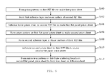
- FIG. 6 is a flowchart illustrating a process of manufacturing the composite sheet for a backlight unit according to an embodiment of the present invention.
- the method of manufacturing the composite sheet for a backlight unit according to the present invention comprises forming a first prism pattern using a UV resin on a first PET film and curing it using UV light thus making a first prism sheet (S100), thinly applying a UV resin on the lower surface of a second PET film thus forming a first adhesive layer (S102), partially embedding the ribs of the prism pattern of the first prism sheet in the first adhesive layer and performing curing using UV light thus making a first flat panel prism sheet (S104), forming a second prism pattern in a direction orthogonal to the direction of the first prism pattern using a UV resin on the upper surface of the first flat panel prism sheet and curing it using UV light thus making a second prism sheet (S106), thinly applying a UV resin on the lower surface of a third PET film thus forming a
- the UV resin is applied in a gel phase to a predetermined thickness on the upper surface of the first PET film which is thin, and the first prism pattern is formed on the upper surface of the first PET film using a prism pattern structure.
- the first PET film having the first prism pattern formed on the upper surface thereof is cured using UV light, thus manufacturing the first prism sheet.
- the first prism sheet is positioned directly on the printless light guide plate and thus performs the same function as does the diffusion sheet.
- the UV resin is applied in a gel phase to a predetermined thickness on the lower surface of the second PET film which is thin, thus forming the first adhesive layer.
- the ribs of the first prism pattern of the first prism sheet are partially embedded in the first adhesive layer and then curing is performed using UV light, thus manufacturing the first flat panel prism sheet.
- the UV resin is applied in a gel phase to a predetermined thickness on the upper surface of the second PET film of the first flat panel prism sheet and the second prism pattern is formed on the upper surface of the second PET film using the prism pattern structure.
- the second prism pattern is in a direction orthogonal to the direction of the first prism pattern.
- the second PET film having the second prism pattern on the upper surface thereof is cured using UV light, thus manufacturing the second prism sheet.
- the second prism sheet functions to convert light, which is incident from the first prism sheet, into a perpendicular direction.
- the UV resin is applied in a gel phase to a predetermined thickness on the lower surface of the third PET film which is thin, thus forming the second adhesive layer.
- the ribs of the second prism sheet are partially embedded in the second adhesive layer and then cured using UV light, thus manufacturing the second flat panel prism sheet.
- the UV resin is applied in a gel phase to a predetermined thickness on the upper surface of the second flat panel prism sheet, and the micro-lens pattern is formed using a micro-lens pattern structure.
- UV curing is performed, thereby manufacturing the composite sheet according to the present invention.
- the composite sheet according to the present invention may be provided in the form of only the second flat panel prism sheet which is integrated with the first flat panel prism sheet.
- the third PET of the second flat panel prism sheet may play a role as a protective sheet.
- the embodiments as described above correspond to some of the variety of embodiments of the present invention.
- the composite sheet for a backlight unit using the printless light guide plate in LCD-TVs specifically, the composite sheet comprising the first prism sheet which performs the function of a diffusion sheet, the second prism sheet integrated with the upper surface of the first prism sheet in a direction orthogonal to the first prism sheet to perform a light condensing function, and a protective sheet or a lens sheet integrated with the upper surface of the second prism sheet, and the method of manufacturing the same may be variously embodied, which is naturally incorporated into the spirit and scope of the present invention.
Landscapes
- Physics & Mathematics (AREA)
- Optics & Photonics (AREA)
- General Physics & Mathematics (AREA)
- Engineering & Computer Science (AREA)
- Manufacturing & Machinery (AREA)
- Nonlinear Science (AREA)
- Crystallography & Structural Chemistry (AREA)
- Chemical & Material Sciences (AREA)
- Mathematical Physics (AREA)
- Planar Illumination Modules (AREA)
- Optical Elements Other Than Lenses (AREA)
- Liquid Crystal (AREA)
- Laminated Bodies (AREA)
- General Engineering & Computer Science (AREA)
Applications Claiming Priority (1)
| Application Number | Priority Date | Filing Date | Title |
|---|---|---|---|
| KR1020110104024A KR20130039463A (ko) | 2011-10-12 | 2011-10-12 | 백라이트유니트용 복합시트 및 그 제조 방법 |
Publications (2)
| Publication Number | Publication Date |
|---|---|
| EP2581769A2 true EP2581769A2 (fr) | 2013-04-17 |
| EP2581769A3 EP2581769A3 (fr) | 2013-07-10 |
Family
ID=47257430
Family Applications (1)
| Application Number | Title | Priority Date | Filing Date |
|---|---|---|---|
| EP12186715.4A Withdrawn EP2581769A3 (fr) | 2011-10-12 | 2012-09-28 | Multi-feuille pour unité de rétroéclairage et procédé associé |
Country Status (6)
| Country | Link |
|---|---|
| US (2) | US20130095297A1 (fr) |
| EP (1) | EP2581769A3 (fr) |
| JP (1) | JP2013083950A (fr) |
| KR (1) | KR20130039463A (fr) |
| CN (1) | CN103115324A (fr) |
| TW (1) | TWI484261B (fr) |
Cited By (1)
| Publication number | Priority date | Publication date | Assignee | Title |
|---|---|---|---|---|
| CN104698517A (zh) * | 2013-12-09 | 2015-06-10 | 纬创资通股份有限公司 | 光学膜片、光学膜片组件及光学膜片的制造方法 |
Families Citing this family (5)
| Publication number | Priority date | Publication date | Assignee | Title |
|---|---|---|---|---|
| CN103760626B (zh) * | 2013-12-26 | 2016-03-02 | 明基材料有限公司 | 调光薄膜 |
| WO2016136786A1 (fr) | 2015-02-27 | 2016-09-01 | シャープ株式会社 | Élément optique de type stratifié, dispositif d'éclairage, dispositif d'affichage, et dispositif de réception de télévision |
| JP6872330B2 (ja) * | 2015-09-28 | 2021-05-19 | 日東電工株式会社 | 光学部材、ならびに、該光学部材を用いた偏光板のセットおよび液晶表示装置 |
| US20190143616A1 (en) * | 2016-06-03 | 2019-05-16 | Lms Co., Ltd. | Method and apparatus for manufacturing optical sheet module |
| KR20190134946A (ko) | 2018-05-24 | 2019-12-05 | 삼성디스플레이 주식회사 | 복합 시트 및 이를 포함하는 표시 장치 |
Family Cites Families (21)
| Publication number | Priority date | Publication date | Assignee | Title |
|---|---|---|---|---|
| US5598280A (en) * | 1993-03-23 | 1997-01-28 | Dai Nippon Printing Co., Ltd. | Film lens and a surface light source using the same |
| US5995288A (en) * | 1997-04-22 | 1999-11-30 | Dai Nippon Printing Co., Ltd. | Optical sheet optical sheet lamination light source device, and light-transmissive type display apparatus |
| KR100271672B1 (ko) * | 1998-05-20 | 2000-11-15 | 구본준 | 시이트 구조의 광학소자 및 그를 이용한 백라이트 유니트 |
| US6628460B1 (en) * | 1998-08-05 | 2003-09-30 | Mitsubishi Rayon Co., Ltd. | Lens sheet and method for producing the same |
| JP4049624B2 (ja) * | 2001-07-27 | 2008-02-20 | 株式会社エンプラス | 面光源装置、画像表示装置及び導光板 |
| JP4019886B2 (ja) * | 2002-09-30 | 2007-12-12 | オムロン株式会社 | 光学フィルム、面光源装置及び液晶表示装置 |
| US7314652B2 (en) * | 2003-02-28 | 2008-01-01 | General Electric Company | Diffuser for flat panel display |
| US6846089B2 (en) * | 2003-05-16 | 2005-01-25 | 3M Innovative Properties Company | Method for stacking surface structured optical films |
| KR100717499B1 (ko) * | 2003-11-12 | 2007-05-14 | 엘지전자 주식회사 | 프리즘 시트, 백라이트 어셈블리 및 디스플레이 장치 |
| KR20060015174A (ko) * | 2004-08-13 | 2006-02-16 | 삼성전자주식회사 | 프리즘 시트 및 이를 구비한 액정표시장치 |
| TW200600919A (en) * | 2004-06-22 | 2006-01-01 | Samsung Electronics Co Ltd | Optical film, backlight assembly and liquid crystal display device having the same |
| US20060164860A1 (en) * | 2005-01-26 | 2006-07-27 | Sanyo Epson Imaging Devices Corp. | Liquid crystal display device |
| JP2007065358A (ja) * | 2005-08-31 | 2007-03-15 | Fujifilm Corp | ディスプレイ用光学シート及びその製造方法 |
| JP2007155938A (ja) * | 2005-12-01 | 2007-06-21 | Fujifilm Corp | ディスプレイ用光学シート及びその製造方法 |
| JP2008003233A (ja) * | 2006-06-21 | 2008-01-10 | Fujifilm Corp | ディスプレイ用光学シート及びその製造方法 |
| KR100848664B1 (ko) * | 2006-11-01 | 2008-07-28 | 성기숙 | 백라이트 유닛용 평판형 프리즘 시트 및 그 제조방법 |
| KR100854752B1 (ko) * | 2007-02-01 | 2008-08-27 | 온누리전자(주) | 확산 수단이 일체화된 백라이트 유닛용 프리즘 시트 및 그제조방법 |
| KR20080072197A (ko) * | 2007-02-01 | 2008-08-06 | 삼성전자주식회사 | 휘도 특성이 개선된 편광 도광판 및 이의 제작 방법 |
| US20090274876A1 (en) * | 2008-04-30 | 2009-11-05 | Dong-Yih Liou | Match of two brightness enhancement films |
| CN103392134B (zh) * | 2011-02-22 | 2016-05-11 | 皇家飞利浦有限公司 | 包括棱柱形层堆叠的准直器以及包括这种准直器的照明单元 |
| JP5789134B2 (ja) * | 2011-06-16 | 2015-10-07 | 株式会社ジャパンディスプレイ | 照明装置、表示装置及び液晶表示装置 |
-
2011
- 2011-10-12 KR KR1020110104024A patent/KR20130039463A/ko not_active Ceased
-
2012
- 2012-09-13 US US13/614,070 patent/US20130095297A1/en not_active Abandoned
- 2012-09-14 JP JP2012203458A patent/JP2013083950A/ja active Pending
- 2012-09-14 TW TW101133613A patent/TWI484261B/zh not_active IP Right Cessation
- 2012-09-24 CN CN201210356162XA patent/CN103115324A/zh active Pending
- 2012-09-28 EP EP12186715.4A patent/EP2581769A3/fr not_active Withdrawn
-
2015
- 2015-04-10 US US14/684,043 patent/US20150211711A1/en not_active Abandoned
Non-Patent Citations (1)
| Title |
|---|
| None |
Cited By (2)
| Publication number | Priority date | Publication date | Assignee | Title |
|---|---|---|---|---|
| CN104698517A (zh) * | 2013-12-09 | 2015-06-10 | 纬创资通股份有限公司 | 光学膜片、光学膜片组件及光学膜片的制造方法 |
| CN104698517B (zh) * | 2013-12-09 | 2017-02-22 | 纬创资通股份有限公司 | 光学膜片、光学膜片组件及光学膜片的制造方法 |
Also Published As
| Publication number | Publication date |
|---|---|
| TWI484261B (zh) | 2015-05-11 |
| KR20130039463A (ko) | 2013-04-22 |
| TW201316091A (zh) | 2013-04-16 |
| CN103115324A (zh) | 2013-05-22 |
| US20150211711A1 (en) | 2015-07-30 |
| JP2013083950A (ja) | 2013-05-09 |
| EP2581769A3 (fr) | 2013-07-10 |
| US20130095297A1 (en) | 2013-04-18 |
Similar Documents
| Publication | Publication Date | Title |
|---|---|---|
| US9182523B2 (en) | Optical film and manufacturing method thereof, liquid cristal display apparatus using the optical film | |
| US20080049330A1 (en) | Light directing laminate | |
| EP2581769A2 (fr) | Multi-feuille pour unité de rétroéclairage et procédé associé | |
| EP3125028B1 (fr) | Dispositif d'affichage à cristaux liquides | |
| JP2010156784A (ja) | 液晶表示装置 | |
| US7859612B2 (en) | Light concentrating sheet, backlight unit including the light concentrating sheet and liquid crystal display module including the backlight unit | |
| KR20110075719A (ko) | 패턴 도광판, 그 제조방법 및 이를 이용한 액정표시장치 백라이트 유닛 | |
| US8421852B2 (en) | Method for manufacturing stereoscopic image display apparatus and stereoscopic image display apparatus | |
| US20140125900A1 (en) | Lcd assemblies and methods for making the same | |
| KR20170051788A (ko) | 액정 표시장치 및 그 제조방법 | |
| KR101868522B1 (ko) | 광학시트 및 이의 제조방법 | |
| US8675155B2 (en) | Liquid crystal display device comprising a first polarizing plate with a cut portion formed directly below a driving chip wherein the cut portion is covered by a bottom surface of a first substrate | |
| US20110038139A1 (en) | Optical film with reduced distortion, method of manufacturing the same, and display apparatus having the same | |
| KR100932606B1 (ko) | 광학필름 및 이를 포함하는 백라이트유닛 | |
| KR20140021925A (ko) | 백라이트 유니트용 광학 시트 및 그 제조 방법 | |
| KR101749750B1 (ko) | 백라이트 유닛 및 액정표시장치 | |
| KR20180056580A (ko) | 고휘도 필름을 포함하는 액정표시장치 | |
| KR101090937B1 (ko) | 구조화된 광학 시트의 패키지 및 그 제조 방법 | |
| KR101264725B1 (ko) | 표시장치 | |
| KR102323788B1 (ko) | 액정표시장치 및 액정표시장치용 도광판 제조방법 | |
| KR102280107B1 (ko) | 광학시트와 이를 구비한 백라이트 유닛 | |
| KR102666668B1 (ko) | 광학용 양면 점착 시트 | |
| KR20170003273A (ko) | 일체형 복합 광학시트 | |
| KR101336939B1 (ko) | 백라이트유니트용 복합시트 및 그 제조 방법 | |
| KR101336937B1 (ko) | 백라이트유니트용 복합시트 및 그 제조 방법 |
Legal Events
| Date | Code | Title | Description |
|---|---|---|---|
| PUAI | Public reference made under article 153(3) epc to a published international application that has entered the european phase |
Free format text: ORIGINAL CODE: 0009012 |
|
| AK | Designated contracting states |
Kind code of ref document: A2 Designated state(s): AL AT BE BG CH CY CZ DE DK EE ES FI FR GB GR HR HU IE IS IT LI LT LU LV MC MK MT NL NO PL PT RO RS SE SI SK SM TR |
|
| AX | Request for extension of the european patent |
Extension state: BA ME |
|
| PUAL | Search report despatched |
Free format text: ORIGINAL CODE: 0009013 |
|
| AK | Designated contracting states |
Kind code of ref document: A3 Designated state(s): AL AT BE BG CH CY CZ DE DK EE ES FI FR GB GR HR HU IE IS IT LI LT LU LV MC MK MT NL NO PL PT RO RS SE SI SK SM TR |
|
| AX | Request for extension of the european patent |
Extension state: BA ME |
|
| RIC1 | Information provided on ipc code assigned before grant |
Ipc: G02F 1/1333 20060101ALI20130531BHEP Ipc: G02B 6/00 20060101AFI20130531BHEP Ipc: F21V 8/00 20060101ALN20130531BHEP |
|
| STAA | Information on the status of an ep patent application or granted ep patent |
Free format text: STATUS: THE APPLICATION IS DEEMED TO BE WITHDRAWN |
|
| 18D | Application deemed to be withdrawn |
Effective date: 20140111 |