EP2581920A2 - Electroaimant - Google Patents
Electroaimant Download PDFInfo
- Publication number
- EP2581920A2 EP2581920A2 EP12007115.4A EP12007115A EP2581920A2 EP 2581920 A2 EP2581920 A2 EP 2581920A2 EP 12007115 A EP12007115 A EP 12007115A EP 2581920 A2 EP2581920 A2 EP 2581920A2
- Authority
- EP
- European Patent Office
- Prior art keywords
- plunger
- connection
- central part
- electromagnet according
- fastening
- Prior art date
- Legal status (The legal status is an assumption and is not a legal conclusion. Google has not performed a legal analysis and makes no representation as to the accuracy of the status listed.)
- Granted
Links
- 239000013013 elastic material Substances 0.000 claims abstract description 8
- 229920001971 elastomer Polymers 0.000 claims description 9
- 239000000806 elastomer Substances 0.000 claims description 6
- 239000007788 liquid Substances 0.000 claims description 6
- 239000011324 bead Substances 0.000 claims description 5
- 229920002725 thermoplastic elastomer Polymers 0.000 claims description 5
- 229920005560 fluorosilicone rubber Polymers 0.000 claims description 4
- 239000000853 adhesive Substances 0.000 claims description 2
- 230000001070 adhesive effect Effects 0.000 claims description 2
- 229920001296 polysiloxane Polymers 0.000 claims 1
- 229920003051 synthetic elastomer Polymers 0.000 claims 1
- 239000005061 synthetic rubber Substances 0.000 claims 1
- 238000007789 sealing Methods 0.000 abstract description 2
- 239000012528 membrane Substances 0.000 description 10
- 238000000926 separation method Methods 0.000 description 9
- 239000000463 material Substances 0.000 description 8
- 229920002943 EPDM rubber Polymers 0.000 description 3
- 244000043261 Hevea brasiliensis Species 0.000 description 3
- 229920000459 Nitrile rubber Polymers 0.000 description 3
- 229920006168 hydrated nitrile rubber Polymers 0.000 description 3
- 229920003052 natural elastomer Polymers 0.000 description 3
- 229920001194 natural rubber Polymers 0.000 description 3
- 229920001084 poly(chloroprene) Polymers 0.000 description 3
- 229920001343 polytetrafluoroethylene Polymers 0.000 description 3
- 239000004810 polytetrafluoroethylene Substances 0.000 description 3
- 239000005060 rubber Substances 0.000 description 3
- 229920006169 Perfluoroelastomer Polymers 0.000 description 2
- -1 Polytetrafluorethylen Polymers 0.000 description 2
- 238000011109 contamination Methods 0.000 description 2
- 230000001419 dependent effect Effects 0.000 description 2
- 230000005489 elastic deformation Effects 0.000 description 2
- 230000002349 favourable effect Effects 0.000 description 2
- 238000000034 method Methods 0.000 description 2
- 238000003860 storage Methods 0.000 description 2
- 229920003048 styrene butadiene rubber Polymers 0.000 description 2
- 238000004804 winding Methods 0.000 description 2
- KUDUQBURMYMBIJ-UHFFFAOYSA-N 2-prop-2-enoyloxyethyl prop-2-enoate Chemical compound C=CC(=O)OCCOC(=O)C=C KUDUQBURMYMBIJ-UHFFFAOYSA-N 0.000 description 1
- 239000002174 Styrene-butadiene Substances 0.000 description 1
- 229920006311 Urethane elastomer Polymers 0.000 description 1
- 229920000800 acrylic rubber Polymers 0.000 description 1
- 230000009286 beneficial effect Effects 0.000 description 1
- 150000001875 compounds Chemical class 0.000 description 1
- 238000005260 corrosion Methods 0.000 description 1
- 230000007797 corrosion Effects 0.000 description 1
- 230000007423 decrease Effects 0.000 description 1
- 230000000694 effects Effects 0.000 description 1
- 239000013536 elastomeric material Substances 0.000 description 1
- 230000005288 electromagnetic effect Effects 0.000 description 1
- QHZOMAXECYYXGP-UHFFFAOYSA-N ethene;prop-2-enoic acid Chemical compound C=C.OC(=O)C=C QHZOMAXECYYXGP-UHFFFAOYSA-N 0.000 description 1
- 239000012530 fluid Substances 0.000 description 1
- 229920002313 fluoropolymer Polymers 0.000 description 1
- 239000004811 fluoropolymer Substances 0.000 description 1
- 238000009472 formulation Methods 0.000 description 1
- 238000007654 immersion Methods 0.000 description 1
- 238000003780 insertion Methods 0.000 description 1
- 230000037431 insertion Effects 0.000 description 1
- 238000005304 joining Methods 0.000 description 1
- 239000000696 magnetic material Substances 0.000 description 1
- 239000000203 mixture Substances 0.000 description 1
- 229920000058 polyacrylate Polymers 0.000 description 1
- 229920000728 polyester Polymers 0.000 description 1
- 238000010008 shearing Methods 0.000 description 1
- 238000004904 shortening Methods 0.000 description 1
- 229920002379 silicone rubber Polymers 0.000 description 1
- 239000004945 silicone rubber Substances 0.000 description 1
- 230000008719 thickening Effects 0.000 description 1
- 238000004073 vulcanization Methods 0.000 description 1
- 238000003466 welding Methods 0.000 description 1
Images
Classifications
-
- H—ELECTRICITY
- H01—ELECTRIC ELEMENTS
- H01F—MAGNETS; INDUCTANCES; TRANSFORMERS; SELECTION OF MATERIALS FOR THEIR MAGNETIC PROPERTIES
- H01F7/00—Magnets
- H01F7/06—Electromagnets; Actuators including electromagnets
- H01F7/08—Electromagnets; Actuators including electromagnets with armatures
- H01F7/128—Encapsulating, encasing or sealing
-
- F—MECHANICAL ENGINEERING; LIGHTING; HEATING; WEAPONS; BLASTING
- F16—ENGINEERING ELEMENTS AND UNITS; GENERAL MEASURES FOR PRODUCING AND MAINTAINING EFFECTIVE FUNCTIONING OF MACHINES OR INSTALLATIONS; THERMAL INSULATION IN GENERAL
- F16K—VALVES; TAPS; COCKS; ACTUATING-FLOATS; DEVICES FOR VENTING OR AERATING
- F16K27/00—Construction of housing; Use of materials therefor
- F16K27/02—Construction of housing; Use of materials therefor of lift valves
- F16K27/029—Electromagnetically actuated valves
-
- F—MECHANICAL ENGINEERING; LIGHTING; HEATING; WEAPONS; BLASTING
- F16—ENGINEERING ELEMENTS AND UNITS; GENERAL MEASURES FOR PRODUCING AND MAINTAINING EFFECTIVE FUNCTIONING OF MACHINES OR INSTALLATIONS; THERMAL INSULATION IN GENERAL
- F16K—VALVES; TAPS; COCKS; ACTUATING-FLOATS; DEVICES FOR VENTING OR AERATING
- F16K31/00—Actuating devices; Operating means; Releasing devices
- F16K31/02—Actuating devices; Operating means; Releasing devices electric; magnetic
- F16K31/06—Actuating devices; Operating means; Releasing devices electric; magnetic using a magnet, e.g. diaphragm valves, cutting off by means of a liquid
-
- F—MECHANICAL ENGINEERING; LIGHTING; HEATING; WEAPONS; BLASTING
- F16—ENGINEERING ELEMENTS AND UNITS; GENERAL MEASURES FOR PRODUCING AND MAINTAINING EFFECTIVE FUNCTIONING OF MACHINES OR INSTALLATIONS; THERMAL INSULATION IN GENERAL
- F16K—VALVES; TAPS; COCKS; ACTUATING-FLOATS; DEVICES FOR VENTING OR AERATING
- F16K41/00—Spindle sealings
- F16K41/10—Spindle sealings with diaphragm, e.g. shaped as bellows or tube
Definitions
- the invention relates to an electromagnet, in particular for media-controlling valves, in which in an armature space a movably mounted, acting on a plunger armature and a coil of stromstromf technologically occurring wire carrying coil is provided and the armature space limiting magnetic core has a plunger bore which the axially movable plunger receives and a, at least partially made of elastic material existing media or liquid-tight demarcation element between the plunger and the magnetic core is provided.
- valves In the prior art, generic electromagnets are well known for example for the actuation of valves.
- the area of application of the valves is often very different. They are also used, for example, to control aggressive media flows (liquid or gaseous). Often it is undesirable that the aggressive medium (for example, contamination in the medium, changed viscosity, the medium to be switched is chemically incompatible with the magnetic material, this dissolves, for example) in the armature space. It is therefore known to fill the armature space with a defined liquid and to provide a demarcation element between the armature space and the valve space at a suitable location. In the prior art, a separation membrane is used as a demarcation element.
- the diaphragm By filling the armature space with an armature space liquid, the diaphragm is pressure balanced and the possibly considerable pressure load of the electromagnet (this can be up to 200 bar and more, for example in hydraulic applications) has no effect on the compressive strength of the electromagnet.
- the substantially disc-shaped separating membrane is attached on the one hand to the plunger and radially outward on the magnetic core, especially in the plunger bore.
- the plunger movement which is caused on the one hand by the electromagnetic effect (the coil of electrical current flowing through the coil windings generate a magnetic field which moves the armature in the armature space and this movement is transmitted to the plunger, or the return movement takes place, for example, by a reversal of the Electromagnet or by suitable mechanical elements, for example, a return spring or the like) is substantially perpendicular to the flat, disc-like arrangement of Diaphragm.
- the caused by the anchor or the plunger stroke of a few tenths of a millimeter, millimeters or up to 5-8 millimeters must then be carried out in a suitable manner by the separation membrane, which leads to a corresponding mechanical stress on the separation membrane.
- the known separation membrane consist of an elastic material, wherein it is observed that the maximum deformation in the region of the smallest radius or smallest cross section in the separation membrane form, that is, the separation membrane is significantly burdened in particular in the attachment area on the plunger by a hinge-like movement.
- the plunger movement is derived from the armature movement (the plunger is, for example, firmly connected to the armature or floating with corresponding return elements floating on it) and the immersion of the plunger from the inside of the solenoid causes a volume compensation in the Anchor space and the necessarily associated with the armature space plunger bore.
- This relative volume change is to be compensated by the demarcation element accordingly and leads to a compensating movement of the separation membrane.
- the armature movement and the compensating movement of the separation membrane is in opposite directions. This leads to a considerable additional mechanical stress on the separating diaphragm due to shearing forces, which leads to a significant reduction in the service life on the one hand or a limitation of the possible stroke on the other hand.
- the present invention has the object to overcome at least one of the aforementioned disadvantages.
- the invention is based on an electromagnet as described above and proposes that the demarcation element has a fastening region for a tight connection of the demarcation element with the plunger, a connection region for a tight connection of the demarcation element with the magnetic core and a middle part provided between the attachment region and the connection region and the middle part surrounding at least a partial length of the plunger hose or sleeve-like.
- substantially planar design separation membrane as a delimitation element is now proposed in the inventive solution, a significantly modified embodiment of the demarcation element.
- the whistle of the invention is that in the demarcation element, a central part is provided which surrounds at least a partial length of the plunger hose and sleeve-like. Clever way, the entire delimitation element is made of an elastomer in one piece, but without limiting the invention thereto. The central part extends substantially parallel to the plunger and undergoes a corresponding mechanical stress when the plunger is moved.
- a significant advantage of the invention is in particular that the relative stress of the demarcation element can be influenced by the length of the central part or the stroke of the electromagnet according to the invention can be increased by extending the middle part.
- the change in position of the plunger to be compensated (its stroke) is distributed over a larger area with the consequence of a lower mechanical load of the elastomer in the middle part. This circumstance can of course be exploited to realize electromagnets with relatively large strokes, which are used in aggressive media and the armature space should not be acted upon with these media.
- the compensating movement of the diaphragm is now no longer hinged and with a corresponding load of the smallest diameter - that is, the attachment region of the delimitation element on the plunger - but preferably substantially in Middle part, in which there is also correspondingly more elastic material available. It follows with the proposal according to the invention that the motion components acting on the demarcation element in the armature or plunger movement on the one hand and the volume compensation movement on the other hand are uniform. An elastic deformation takes place in the tubular or sleeve-like middle part of the demarcation element, with an elongation of this tubular or sleeve-like middle part, the diameter of the central part is reduced, so that the middle part fits closer to the plunger.
- the compensating movement that occurs in the variant according to the invention is not opposite to the armature movement and does not lead to an additional mechanical load of the demarcation element.
- the elastic deformation is largely uniformly distributed to the tubular or sleeve-like middle part of the demarcation element.
- the resistances to be overcome are also significantly lower.
- the durability of the proposal according to the invention is considerably improved, with the electromagnet of the invention significantly higher switching numbers are achieved.
- the middle part is substantially parallel or coaxial is arranged to the ram.
- Such alignment allows the material stress in the center portion to be as low as possible and no shear forces, etc., to occur, which are responsible for a significant reduction in the life of the solutions in the prior art.
- Due to the tubular or sleeve-like design of the middle part and the attachment area and the connection area are axially - with respect to the longitudinal extension of the plunger or its direction of movement - offset and provided for the magnetic guide magnetic core takes in a space-saving manner, for example, in the interior of the connection area of Demarcation element for fastening purposes.
- the middle part has a length of at least one, preferably at least two, in particular three ram diameters.
- the central part has a length of at least one, preferably at least two, in particular at least three diameters of the plunger bore and the expansion to the plunger bore.
- the middle part preferably comprises at least five or at least 10, at least 20, at least 30, at least 50 or at least 70 or 80 percent of the thickness of the magnetic core.
- the thickness of the magnetic core is defined by the distance of the valve chamber to the armature space, between which the magnetic core is constructive.
- the magnetic core can also take over a storage function for the plunger, but alternatively the plunger is also axially guided either in the armature itself or in the assembly provided in the valve.
- the advantage of the different possible lengths of the central part, which surrounds the plunger tubular or sleeve-like is that thereby the invention proposed demarcation element is adaptable to the respective characteristics of the electromagnet. So you will be at a high stress of the electromagnet, for example due to high switching numbers and / or high lift rather choose a long middle section in the demarcation element.
- the proposal cleverly achieves that the material of the Mitteilteils claimed parallel to the plunger movement direction by a movement of the plunger, so mechanically loaded, or is steered. A Walk or hinge movement is avoided by the proposal, which contributes significantly to corresponding increase in life.
- hose-like region By extending the hose-like region, for example to a multiple (2, 3, 4, 5, 6 or 7 times the diameter of the ram or a diameter of more than 20% of the magnetic core thickness), large ones can also be used Magnetic strokes, so large strokes of the plunger are realized at the same percentage elongation, in particular the Mitteilteils the demarcation element.
- a homogeneous, consistent wall thickness of the middle part is used, through which - seen in the circumferential direction - a similar behavior of the demarcation element results, which loads the storage and guide elements of the plunger in a similar manner.
- the homogeneous constant cross-section also contributes to a homogeneous constant load on the middle part.
- the cross section of the central part is homogeneous and constant when viewed in the longitudinal direction, this feature referring to the either unswitched or switched state of the electromagnet and not describing the situation of the compensating movement.
- the unloaded, non-steered state of the demarcation element is a homogeneous constant cross-section of the central part in turn favorable for a similar load on the middle part and the resulting life the entire proposed by the invention electromagnet.
- the fastening region is preferably in the form of a ring, bead or annular bead projecting inwards in relation to the middle part.
- the connection region which is provided for a tight connection of the demarcation element to the magnetic core, is designed as a flange or annular flange projecting outwards relative to the middle part.
- a plurality of different connection variants for a tight and mechanically strong connection on the one hand of the connection area with the magnetic core on the other hand is provided with the plunger.
- purely mechanical joining techniques such as a press or clamp connection but also material bonding techniques such as a welding or vulcanization, but also an adhesive bond in which an additional layer can be provided for the compound can be used.
- the arrangement of a mounting collar or a mounting groove on the plunger, the mounting location during assembly of the demarcation element is precisely defined.
- a mounting collar or a mounting groove also serves as an abutment, for example in a press or clamp connection.
- a connection collar or a connection groove for fastening the connection region is provided in the plunger bore or expansion.
- the demarcation element provided according to the invention is produced in one piece and in each case consists of the attachment area and the connection area, which receive the sleeve-like or tubular-like middle part between them.
- the demarcation element has a fastening region and termination region formed from a separate element, which have between them the substantially elastically formed central part.
- the demarcation element consists at least partially of elastic material.
- the demarcation element consists of several individually manufactured parts, which are assembled in a suitable manner afterwards.
- the demarcation element not only consists of homogeneous similar material, but the demarcation element has optimized material properties to the respective field of application and is therefore heterogeneous in this respect.
- the electromagnet according to the invention is shown schematically in the figures in different variants.
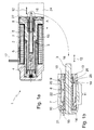
- the in the Fig. 1a and 1b shown electromagnet 1 is used in particular for controlling a valve 24.
- the electromagnet 1 has an armature space 2, in which a movably mounted armature 4 is provided.
- This armature 4 acts on a fixedly or floatingly connected to the armature 4 plunger 3.
- the armature space 2 is surrounded by a coil can be acted upon by electric current 5, which carries the windings of a wire, which can be traversed by current.
- the coil 5 generates a corresponding magnetic field during operation of the electromagnet, which causes the movement of the armature 4 and thus of the plunger 3.
- the armature 3 is axially displaced, whereby then the operation, that is, in the simplest embodiment, an opening or closing of the valve 24 takes place.
- the magnet core 7 adjoins the armature space 2 and limits it in the direction of the valve 24 associated with the electromagnet 1.
- the magnet core 7 has a tappet bore 15 which accommodates the axially movable tappet 3.
- solenoid 1 is used to control a valve 24.
- a valve 24 may for example be used to control aggressive or corrosive media.
- a demarcation element 8 is provided. This demarcation element 8 is formed of an elastic material and extends axially to the plunger 3 in the plunger bore 15. About the demarcation element 8, a liquid-tight closure of the armature space 2 can be achieved with respect to the operated by the solenoid 1 valve 24.
- the demarcation element 8 surrounds the part of the plunger 3, which is directly in operative connection with the valve 24, in the manner of a sleeve or a hose. Due to the elastic design of the demarcation element this can be stretched or compressed by movement of the plunger in the ram movement direction 12 and thereby ensure a permanent seal.
- the demarcation element 8 surrounds the plunger tubular or sleeve-like.
- the fastening element 8 on the one hand has a connection with the plunger 3 in connection, in particular liquid-tight on this adjacent mounting portion 9.
- a connection region 10, which is connected to the magnetic core 7, is provided on the delimitation element 8.
- a liquid-tight connection of demarcation element 8 and anchor 7 is provided.
- a radial projection 25 is provided, which forms a shoulder 26, which is in engagement with the mounting portion 9.
- the mounting portion 9 is in the embodiment of Fig. 1b and 2 B formed as a bead-like thickening of the demarcation element 9. This extends radially relative to the central part 11 of the demarcation element to the plunger 3.
- a clamping ring 19 is provided in order to ensure a securing of the fastening region 9, and to prevent the fastening region 9 from becoming detached from the radial projection 25, a clamping ring 19 is provided.
- the radial projection 25 extends axially to the ram movement direction in the direction of the armature 4 and thereby forms a circumferential mounting collar 18, on which a part of the demarcation element 8 fits tightly.
- the mounting collar has in the course of a chamfer, which tapers to a taper of the diameter of the plunger 3.
- the magnet core protruding beyond the end of the plunger 3 extends into a subsequent to the electromagnet 1 in ram direction 12 valve 24 and actuates this.
- the plunger 3 is passed through the plunger bore 15 in the magnetic core 7 and is there with the armature 4 in combination (see. Fig. 1a and 2a ).
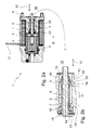
- electromagnets 1 shown differ in the manner of mounting the demarcation element 8 and the magnetic core 7.
- electromagnet 1 available in which the magnetic core 7 already in the in the Fig. 1a shown position is inserted.
- the plunger 3 is in this case already in the plunger bore 15 and projects beyond the magnet core 7 or the plunger bore 15 provided therein.
- the delimitation element 8 is pushed onto the plunger 3 and introduced into the magnet core 7.
- a cover plate 27 is placed on the magnetic core 7.
- This cover plate has a clamping sleeve 22 designed as a sleeve-like extension, which is in the plunger bore 15 and rests against the connection collar 21.
- the demarcation element 8, or its central part 11 extends on the ram bore 15 projecting portion of the plunger 3 along parallel to this and finds its conclusion in the bead-like ring 13, which engages with the mounting collar 18 and the radial projection 25 and slipping of the demarcation element 8 prevented by the plunger.
- An additional assurance is provided by the clamping ring 19, which is also plugged onto the plunger 3 and determines the ring 13 on the plunger 3 or pressed or jammed with this.
- the assembly in the in Fig. 2a shown electromagnet 1 performed such that a component consisting of the plunger 3 with attached demarcation element 8, is provided. This is inserted through the plunger bore 15 in the magnetic core 7 and then secured by the clamping plate 23.
- a connection collar 21 is provided for this purpose, on which the flange 14, which is arranged on the demarcation element 8 and whose connection region 10 forms, rests. An additional assurance is achieved here by placing the clamping plate 23. This prevents slippage of the connection portion 10 from the connection collar 21.
- the central part 11 of the delimitation element 8 extends coaxially to this on the plunger 3 and engages over the provided on the plunger 3 mounting collar 18, which also has a radial projection 25 and a shoulder 26 is formed, with which the ring 13 and the mounting portion 9 of the demarcation element 8 is engaged.
- Tappet side is the delimitation element 8 by a related to Fig. 1b already described clamping ring 19 secured. In this embodiment, no clamping sleeve 22, as in connection with Fig. 1b shown, provided and necessary to perform a backup of the demarcation element 8.
- An assembly of the demarcation element 8 takes place in the direction of arrow B, while in the embodiment of Fig. 1 an assembly in the direction of arrow A takes place.
- Fig. 1b and 2 B show detailed views of the delimitation element 8, which was inserted into the plunger bore 15.
- the demarcation element 8 is connected in the two illustrated embodiments via a clamping connection with the plunger 3. Also, a clamping connection is provided between the magnetic core 7 and the terminal portion 10 of the demarcation element 8.
- the middle part 11 is arranged substantially parallel or coaxial with the plunger 3.
- the central part 11 has a length of three plunger diameters.
- the delimitation element 8 or its middle part 11 moves in the direction of the plunger 3.
- the delimitation element 8 As a result, the delimitation element 8 or its middle part 11 moves in the direction of the plunger 3. From the design of the delimitation element 8 as a sleeve or hose or hose section, there is a uniform reduction in diameter. The wall thickness thus decreases over the entire middle part 11 away to the same extent, if it comes to an expansion of the demarcation element 8. At the same time, the space available in the plunger bore 15 for the inflowing medium is increased by the radial diameter reduction of the demarcation element 8.
- the demarcation element 8 has a bead-like or ring-like fastening region 9 in the exemplary embodiment. This is opposite to the central part 11 projecting radially inward, the It means that it extends radially in the direction of the plunger 3.
- the connection region 10 of the demarcation element 8 is located at the fastening region 9 opposite the end of the central part 11 and is formed as compared to the central part 11 radially outwardly projecting flange 14.
- the flange 14 is arranged annularly around the central part 11 and has a shape corresponding to the connection collar 21, so that a partial engagement of the flange 14 by the connection collar 21 takes place here. To insert the demarcation element 8, this is in the in Fig. 1b shown embodiment from below, that is in the direction of arrow A (see. Fig. 1a ), inserted in the magnetic core 7.
- the assembly consisting of plunger 3 with demarcation element 8 arranged thereon, from the anchor side in the direction of arrow B (see. Fig. 2a ) is inserted into the magnetic core 7 and then secured by the clamping plate 23.
- the assembly consisting of armature 4, plunger 3 and demarcation element 8 can be made available as a component that only in the magnetic core 7 or the assembly that includes the magnetic core 7, are inserted got to.
- an additional cover plate 27 is provided here, which includes a clamping sleeve 22 which brought into engagement with the terminal portion 10 of the demarcation element 8 and the demarcation element 8 in the plunger bore 15 and in the magnetic core 7 secures against accidental falling out. At the same time thereby the fluid-tight seal is ensured.
- the cover plate 27 is additionally secured in the magnetic core 7, for example via a clamping, latching, screwing or other connection that appears suitable.
- the delimitation element 8 is formed in the embodiment of an elastomer and designed such that a high number of switching operations can be performed without fatigue or embrittlement phenomena occur on the demarcation element 8.
- the elastomeric material is resistant to aggressive or corrosive media, which are controlled by the adjoining the solenoid 1 valve 24.
- the electromagnet 1 is shown in the basic position, that is, demarcation element 8 is not stretched or elongated. If the electromagnet 1 is energized, there is a shift of the armature 4 in the armature space 2. In this way, the plunger 3 is further guided into the plunger bore 15 and projects beyond the magnet housing further than shown in the figures. As a result, due to the fact that the delimitation element 8 is fixed in the magnetic core 7, to its elongation or elongation. There is thus a stress on the demarcation element 8 in the longitudinal direction.
Landscapes
- Engineering & Computer Science (AREA)
- General Engineering & Computer Science (AREA)
- Physics & Mathematics (AREA)
- Electromagnetism (AREA)
- Mechanical Engineering (AREA)
- Power Engineering (AREA)
- Magnetically Actuated Valves (AREA)
- Electromagnets (AREA)
Applications Claiming Priority (1)
| Application Number | Priority Date | Filing Date | Title |
|---|---|---|---|
| DE102011115898A DE102011115898A1 (de) | 2011-10-14 | 2011-10-14 | Elektromagnet |
Publications (3)
| Publication Number | Publication Date |
|---|---|
| EP2581920A2 true EP2581920A2 (fr) | 2013-04-17 |
| EP2581920A3 EP2581920A3 (fr) | 2017-12-20 |
| EP2581920B1 EP2581920B1 (fr) | 2018-11-28 |
Family
ID=47115149
Family Applications (1)
| Application Number | Title | Priority Date | Filing Date |
|---|---|---|---|
| EP12007115.4A Not-in-force EP2581920B1 (fr) | 2011-10-14 | 2012-10-11 | Electroaimant |
Country Status (5)
| Country | Link |
|---|---|
| US (1) | US8632051B2 (fr) |
| EP (1) | EP2581920B1 (fr) |
| CN (1) | CN103047468B (fr) |
| BR (1) | BR102012026009B1 (fr) |
| DE (1) | DE102011115898A1 (fr) |
Families Citing this family (6)
| Publication number | Priority date | Publication date | Assignee | Title |
|---|---|---|---|---|
| CN104214339A (zh) * | 2014-09-27 | 2014-12-17 | 零八一电子集团四川力源电子有限公司 | 高速电磁铁的引线柱密封结构 |
| RU171959U1 (ru) * | 2016-09-21 | 2017-06-22 | Акционерное общество "Концерн "Научно-производственное объединение "Аврора" | Герметичный электромагнит |
| DE102017107403A1 (de) * | 2017-04-06 | 2018-10-11 | Kendrion (Villingen) Gmbh | Elektromagnetische Stellvorrichtung insbesondere zum Verstellen von Nockenwellen eines Verbrennungsmotors |
| CN109698052A (zh) * | 2017-10-20 | 2019-04-30 | 三花亚威科电器设备(芜湖)有限公司 | 电磁铁 |
| CN111075929B (zh) * | 2019-11-27 | 2021-12-07 | 维沃移动通信有限公司 | 伸缩组件和电子设备 |
| US20250027574A1 (en) * | 2023-07-21 | 2025-01-23 | Watts Regulator Co. | Retention clip for a valve shaft adapter |
Family Cites Families (27)
| Publication number | Priority date | Publication date | Assignee | Title |
|---|---|---|---|---|
| DE1171282B (de) | 1958-05-07 | 1964-05-27 | Boge Gmbh | Hydro-pneumatischer Einrohr-Teleskopschwingungsdaempfer, insbesondere fuer Kraftfahrzeuge |
| DE1908082U (de) * | 1962-02-01 | 1965-01-07 | Daimler Benz Ag | Hydraulischer schwingungsdaempfer in teleskopbauweise. |
| DE1908082A1 (de) | 1969-02-18 | 1970-09-03 | Adolf Salzer | Radar-Zusatzeinrichtung zur Sichtbarmachung des relativen Kurses aller vom Radarbild erfassten Schiffe |
| JPS51110130A (en) | 1975-03-25 | 1976-09-29 | Nissan Motor | Nainenkikanno taikiosenboshisochi |
| FR2308031A1 (fr) * | 1975-04-18 | 1976-11-12 | Allinquant Fernand | Joint d'etancheite pour tiges coulissantes |
| DE3136174A1 (de) * | 1981-09-12 | 1983-03-31 | Mannesmann Rexroth GmbH, 8770 Lohr | "druckregelventil" |
| DE3240959A1 (de) * | 1981-11-11 | 1983-05-19 | Lucas Industries P.L.C., Birmingham, West Midlands | Fluidsteuerventil |
| DE3616844C2 (de) | 1986-05-17 | 1995-05-24 | Festo Kg | Führungs- und Dichtungsanordnung für die Kolbenstange eines Kolben-Zylinder-Aggregats |
| DE3721208A1 (de) | 1987-06-26 | 1989-01-05 | Rexroth Mannesmann Gmbh | Magnetventil |
| JP3671524B2 (ja) * | 1996-07-18 | 2005-07-13 | 株式会社デンソー | 電磁弁 |
| DE19733660A1 (de) * | 1997-08-04 | 1999-02-25 | Bosch Gmbh Robert | Elektromagnetisches Druckregelventil |
| US6116570A (en) * | 1998-03-30 | 2000-09-12 | Siemens Automotive Corporation | Electromagnetic actuator with internal oil system and improved hydraulic lash adjuster |
| EP1046005B1 (fr) * | 1998-09-24 | 2004-06-16 | Robert Bosch Gmbh | Soupape proportionnelle hydraulique a actionnement electromagnetique |
| DE10107115B4 (de) * | 2001-02-14 | 2004-09-30 | Robert Bosch Gmbh | Drucksteuerventil |
| DE10161388A1 (de) * | 2001-12-14 | 2003-07-03 | Bayer Ag | Ventil |
| JP2003314743A (ja) * | 2002-04-19 | 2003-11-06 | Toyoda Mach Works Ltd | 電磁弁 |
| EP1511954B1 (fr) * | 2002-06-12 | 2006-01-11 | FSP Fluid Systems Partners Holding AG | Soupape a visser |
| DE10238840A1 (de) * | 2002-08-23 | 2004-03-04 | Thomas Magnete Gmbh | Magnetanordnung |
| DE102004051575B4 (de) * | 2004-10-22 | 2015-12-17 | Bosch Rexroth Aktiengesellschaft | Wegesitzventil |
| US7347172B2 (en) * | 2005-05-10 | 2008-03-25 | International Engine Intellectual Property Company, Llc | Hydraulic valve actuation system with valve lash adjustment |
| US8127791B2 (en) * | 2005-12-21 | 2012-03-06 | Saturn Electronics & Engineering, Inc. | Solenoid operated fluid control valve |
| DE102006042215B4 (de) * | 2006-09-08 | 2018-05-30 | Schaeffler Technologies AG & Co. KG | Elektromagnetische Stelleinheit |
| DE102006042214A1 (de) * | 2006-09-08 | 2008-03-27 | Schaeffler Kg | Elektromagnetische Stelleinheit |
| DE102007039148B4 (de) | 2007-08-18 | 2011-06-01 | Thomas Magnete Gmbh | Schnellschaltmagnet |
| DE102008030454A1 (de) | 2008-06-26 | 2009-12-31 | Hydac Electronic Gmbh | Betätigungsvorrichtung |
| US20100180875A1 (en) * | 2009-01-22 | 2010-07-22 | The Scuderi Group, Llc | Seating control device for a valve for a split-cycle engine |
| DE102009041188A1 (de) * | 2009-09-14 | 2011-03-24 | Svm Schultz Verwaltungs-Gmbh & Co. Kg | Elektromagnet mit einem Anker |
-
2011
- 2011-10-14 DE DE102011115898A patent/DE102011115898A1/de not_active Ceased
- 2011-10-14 US US13/273,855 patent/US8632051B2/en not_active Expired - Fee Related
-
2012
- 2012-10-10 BR BR102012026009-3A patent/BR102012026009B1/pt not_active IP Right Cessation
- 2012-10-11 EP EP12007115.4A patent/EP2581920B1/fr not_active Not-in-force
- 2012-10-12 CN CN201210387580.5A patent/CN103047468B/zh not_active Expired - Fee Related
Non-Patent Citations (1)
| Title |
|---|
| None |
Also Published As
| Publication number | Publication date |
|---|---|
| EP2581920A3 (fr) | 2017-12-20 |
| BR102012026009A2 (pt) | 2014-03-04 |
| CN103047468B (zh) | 2017-06-06 |
| CN103047468A (zh) | 2013-04-17 |
| US8632051B2 (en) | 2014-01-21 |
| DE102011115898A1 (de) | 2013-04-18 |
| US20130093548A1 (en) | 2013-04-18 |
| EP2581920B1 (fr) | 2018-11-28 |
| BR102012026009B1 (pt) | 2021-09-28 |
Similar Documents
| Publication | Publication Date | Title |
|---|---|---|
| EP2581920B1 (fr) | Electroaimant | |
| EP1914465B1 (fr) | Connexion à brides pour tuyaux | |
| EP3237734A1 (fr) | Vanne | |
| EP3130828B1 (fr) | Vanne hydraulique | |
| DE102013200533B4 (de) | Ventilpatrone | |
| EP3696455A1 (fr) | Soupape à commande électromagnétique | |
| DE102007005916A1 (de) | Doppelankermagnetventil mit zwei Ventilöffnungen und mindestens einem die Ventilöffnungen verbindenden Kanal | |
| DE102008057575A1 (de) | Aktor mit einem magnetorheologischen Elastomer-Element | |
| DE102016112408B4 (de) | Axial durchströmbares Fluidventil | |
| EP4058697B1 (fr) | Vanne de commande ou de commutation pour un circuit d'agent de refroidissement d'un véhicule à moteur | |
| DE102009022092A1 (de) | Elektromagnetisches Ventil | |
| DE102018127810A1 (de) | Axial durchströmbares Fluidventil | |
| DE102011052516A1 (de) | Elektromagnetventil | |
| EP2226526A2 (fr) | Unité de cylindre à pistons | |
| EP2157587A2 (fr) | Tube polaire et aimant d'actionnement en étant équipé | |
| EP1450087B1 (fr) | Soupape électromagnétique | |
| WO2017186449A1 (fr) | Soupape électromagnétique et procédé de fonctionnement | |
| WO2015049054A1 (fr) | Induit mobile d'une électrovanne et électrovanne équipée d'un tel induit | |
| EP2966331A1 (fr) | Soupape de levage dotee de membrane | |
| EP2600044B1 (fr) | Aimant électrique doté d'un corps de soupape | |
| DE102023122426A1 (de) | Dämpfungsventileinrichtung für einen Stoßdämpfer eines Kraftfahrzeugs | |
| DE102011100286B4 (de) | Ventil | |
| WO2019121532A1 (fr) | Soupape | |
| EP2228575B1 (fr) | Electroaimant | |
| DE10351106A1 (de) | Magnetventil |
Legal Events
| Date | Code | Title | Description |
|---|---|---|---|
| PUAI | Public reference made under article 153(3) epc to a published international application that has entered the european phase |
Free format text: ORIGINAL CODE: 0009012 |
|
| AK | Designated contracting states |
Kind code of ref document: A2 Designated state(s): AL AT BE BG CH CY CZ DE DK EE ES FI FR GB GR HR HU IE IS IT LI LT LU LV MC MK MT NL NO PL PT RO RS SE SI SK SM TR |
|
| AX | Request for extension of the european patent |
Extension state: BA ME |
|
| PUAL | Search report despatched |
Free format text: ORIGINAL CODE: 0009013 |
|
| AK | Designated contracting states |
Kind code of ref document: A3 Designated state(s): AL AT BE BG CH CY CZ DE DK EE ES FI FR GB GR HR HU IE IS IT LI LT LU LV MC MK MT NL NO PL PT RO RS SE SI SK SM TR |
|
| AX | Request for extension of the european patent |
Extension state: BA ME |
|
| RIC1 | Information provided on ipc code assigned before grant |
Ipc: H01F 7/128 20060101ALI20171115BHEP Ipc: H01F 7/127 20060101ALI20171115BHEP Ipc: H01F 7/126 20060101AFI20171115BHEP |
|
| STAA | Information on the status of an ep patent application or granted ep patent |
Free format text: STATUS: REQUEST FOR EXAMINATION WAS MADE |
|
| 17P | Request for examination filed |
Effective date: 20180125 |
|
| RBV | Designated contracting states (corrected) |
Designated state(s): AL AT BE BG CH CY CZ DE DK EE ES FI FR GB GR HR HU IE IS IT LI LT LU LV MC MK MT NL NO PL PT RO RS SE SI SK SM TR |
|
| GRAP | Despatch of communication of intention to grant a patent |
Free format text: ORIGINAL CODE: EPIDOSNIGR1 |
|
| STAA | Information on the status of an ep patent application or granted ep patent |
Free format text: STATUS: GRANT OF PATENT IS INTENDED |
|
| INTG | Intention to grant announced |
Effective date: 20180430 |
|
| GRAS | Grant fee paid |
Free format text: ORIGINAL CODE: EPIDOSNIGR3 |
|
| GRAA | (expected) grant |
Free format text: ORIGINAL CODE: 0009210 |
|
| STAA | Information on the status of an ep patent application or granted ep patent |
Free format text: STATUS: THE PATENT HAS BEEN GRANTED |
|
| AK | Designated contracting states |
Kind code of ref document: B1 Designated state(s): AL AT BE BG CH CY CZ DE DK EE ES FI FR GB GR HR HU IE IS IT LI LT LU LV MC MK MT NL NO PL PT RO RS SE SI SK SM TR |
|
| REG | Reference to a national code |
Ref country code: GB Ref legal event code: FG4D Free format text: NOT ENGLISH |
|
| REG | Reference to a national code |
Ref country code: CH Ref legal event code: EP |
|
| REG | Reference to a national code |
Ref country code: AT Ref legal event code: REF Ref document number: 1071181 Country of ref document: AT Kind code of ref document: T Effective date: 20181215 |
|
| REG | Reference to a national code |
Ref country code: DE Ref legal event code: R096 Ref document number: 502012013891 Country of ref document: DE |
|
| REG | Reference to a national code |
Ref country code: IE Ref legal event code: FG4D Free format text: LANGUAGE OF EP DOCUMENT: GERMAN |
|
| REG | Reference to a national code |
Ref country code: NL Ref legal event code: MP Effective date: 20181128 |
|
| REG | Reference to a national code |
Ref country code: LT Ref legal event code: MG4D |
|
| PG25 | Lapsed in a contracting state [announced via postgrant information from national office to epo] |
Ref country code: ES Free format text: LAPSE BECAUSE OF FAILURE TO SUBMIT A TRANSLATION OF THE DESCRIPTION OR TO PAY THE FEE WITHIN THE PRESCRIBED TIME-LIMIT Effective date: 20181128 Ref country code: LT Free format text: LAPSE BECAUSE OF FAILURE TO SUBMIT A TRANSLATION OF THE DESCRIPTION OR TO PAY THE FEE WITHIN THE PRESCRIBED TIME-LIMIT Effective date: 20181128 Ref country code: NO Free format text: LAPSE BECAUSE OF FAILURE TO SUBMIT A TRANSLATION OF THE DESCRIPTION OR TO PAY THE FEE WITHIN THE PRESCRIBED TIME-LIMIT Effective date: 20190228 Ref country code: IS Free format text: LAPSE BECAUSE OF FAILURE TO SUBMIT A TRANSLATION OF THE DESCRIPTION OR TO PAY THE FEE WITHIN THE PRESCRIBED TIME-LIMIT Effective date: 20190328 Ref country code: FI Free format text: LAPSE BECAUSE OF FAILURE TO SUBMIT A TRANSLATION OF THE DESCRIPTION OR TO PAY THE FEE WITHIN THE PRESCRIBED TIME-LIMIT Effective date: 20181128 Ref country code: BG Free format text: LAPSE BECAUSE OF FAILURE TO SUBMIT A TRANSLATION OF THE DESCRIPTION OR TO PAY THE FEE WITHIN THE PRESCRIBED TIME-LIMIT Effective date: 20190228 Ref country code: HR Free format text: LAPSE BECAUSE OF FAILURE TO SUBMIT A TRANSLATION OF THE DESCRIPTION OR TO PAY THE FEE WITHIN THE PRESCRIBED TIME-LIMIT Effective date: 20181128 Ref country code: LV Free format text: LAPSE BECAUSE OF FAILURE TO SUBMIT A TRANSLATION OF THE DESCRIPTION OR TO PAY THE FEE WITHIN THE PRESCRIBED TIME-LIMIT Effective date: 20181128 |
|
| PG25 | Lapsed in a contracting state [announced via postgrant information from national office to epo] |
Ref country code: RS Free format text: LAPSE BECAUSE OF FAILURE TO SUBMIT A TRANSLATION OF THE DESCRIPTION OR TO PAY THE FEE WITHIN THE PRESCRIBED TIME-LIMIT Effective date: 20181128 Ref country code: AL Free format text: LAPSE BECAUSE OF FAILURE TO SUBMIT A TRANSLATION OF THE DESCRIPTION OR TO PAY THE FEE WITHIN THE PRESCRIBED TIME-LIMIT Effective date: 20181128 Ref country code: SE Free format text: LAPSE BECAUSE OF FAILURE TO SUBMIT A TRANSLATION OF THE DESCRIPTION OR TO PAY THE FEE WITHIN THE PRESCRIBED TIME-LIMIT Effective date: 20181128 Ref country code: GR Free format text: LAPSE BECAUSE OF FAILURE TO SUBMIT A TRANSLATION OF THE DESCRIPTION OR TO PAY THE FEE WITHIN THE PRESCRIBED TIME-LIMIT Effective date: 20190301 Ref country code: PT Free format text: LAPSE BECAUSE OF FAILURE TO SUBMIT A TRANSLATION OF THE DESCRIPTION OR TO PAY THE FEE WITHIN THE PRESCRIBED TIME-LIMIT Effective date: 20190328 |
|
| PG25 | Lapsed in a contracting state [announced via postgrant information from national office to epo] |
Ref country code: NL Free format text: LAPSE BECAUSE OF FAILURE TO SUBMIT A TRANSLATION OF THE DESCRIPTION OR TO PAY THE FEE WITHIN THE PRESCRIBED TIME-LIMIT Effective date: 20181128 |
|
| PG25 | Lapsed in a contracting state [announced via postgrant information from national office to epo] |
Ref country code: DK Free format text: LAPSE BECAUSE OF FAILURE TO SUBMIT A TRANSLATION OF THE DESCRIPTION OR TO PAY THE FEE WITHIN THE PRESCRIBED TIME-LIMIT Effective date: 20181128 Ref country code: PL Free format text: LAPSE BECAUSE OF FAILURE TO SUBMIT A TRANSLATION OF THE DESCRIPTION OR TO PAY THE FEE WITHIN THE PRESCRIBED TIME-LIMIT Effective date: 20181128 Ref country code: CZ Free format text: LAPSE BECAUSE OF FAILURE TO SUBMIT A TRANSLATION OF THE DESCRIPTION OR TO PAY THE FEE WITHIN THE PRESCRIBED TIME-LIMIT Effective date: 20181128 |
|
| REG | Reference to a national code |
Ref country code: DE Ref legal event code: R097 Ref document number: 502012013891 Country of ref document: DE |
|
| PG25 | Lapsed in a contracting state [announced via postgrant information from national office to epo] |
Ref country code: RO Free format text: LAPSE BECAUSE OF FAILURE TO SUBMIT A TRANSLATION OF THE DESCRIPTION OR TO PAY THE FEE WITHIN THE PRESCRIBED TIME-LIMIT Effective date: 20181128 Ref country code: EE Free format text: LAPSE BECAUSE OF FAILURE TO SUBMIT A TRANSLATION OF THE DESCRIPTION OR TO PAY THE FEE WITHIN THE PRESCRIBED TIME-LIMIT Effective date: 20181128 Ref country code: SM Free format text: LAPSE BECAUSE OF FAILURE TO SUBMIT A TRANSLATION OF THE DESCRIPTION OR TO PAY THE FEE WITHIN THE PRESCRIBED TIME-LIMIT Effective date: 20181128 Ref country code: SK Free format text: LAPSE BECAUSE OF FAILURE TO SUBMIT A TRANSLATION OF THE DESCRIPTION OR TO PAY THE FEE WITHIN THE PRESCRIBED TIME-LIMIT Effective date: 20181128 |
|
| REG | Reference to a national code |
Ref country code: DE Ref legal event code: R082 Ref document number: 502012013891 Country of ref document: DE Representative=s name: PATENTANWAELTE OLBRICHT, BUCHHOLD, KEULERTZ PA, DE |
|
| PLBE | No opposition filed within time limit |
Free format text: ORIGINAL CODE: 0009261 |
|
| STAA | Information on the status of an ep patent application or granted ep patent |
Free format text: STATUS: NO OPPOSITION FILED WITHIN TIME LIMIT |
|
| PG25 | Lapsed in a contracting state [announced via postgrant information from national office to epo] |
Ref country code: SI Free format text: LAPSE BECAUSE OF FAILURE TO SUBMIT A TRANSLATION OF THE DESCRIPTION OR TO PAY THE FEE WITHIN THE PRESCRIBED TIME-LIMIT Effective date: 20181128 |
|
| 26N | No opposition filed |
Effective date: 20190829 |
|
| PG25 | Lapsed in a contracting state [announced via postgrant information from national office to epo] |
Ref country code: TR Free format text: LAPSE BECAUSE OF FAILURE TO SUBMIT A TRANSLATION OF THE DESCRIPTION OR TO PAY THE FEE WITHIN THE PRESCRIBED TIME-LIMIT Effective date: 20181128 |
|
| PG25 | Lapsed in a contracting state [announced via postgrant information from national office to epo] |
Ref country code: MC Free format text: LAPSE BECAUSE OF FAILURE TO SUBMIT A TRANSLATION OF THE DESCRIPTION OR TO PAY THE FEE WITHIN THE PRESCRIBED TIME-LIMIT Effective date: 20181128 |
|
| REG | Reference to a national code |
Ref country code: CH Ref legal event code: PL |
|
| PG25 | Lapsed in a contracting state [announced via postgrant information from national office to epo] |
Ref country code: LI Free format text: LAPSE BECAUSE OF NON-PAYMENT OF DUE FEES Effective date: 20191031 Ref country code: LU Free format text: LAPSE BECAUSE OF NON-PAYMENT OF DUE FEES Effective date: 20191011 Ref country code: CH Free format text: LAPSE BECAUSE OF NON-PAYMENT OF DUE FEES Effective date: 20191031 |
|
| REG | Reference to a national code |
Ref country code: BE Ref legal event code: MM Effective date: 20191031 |
|
| PG25 | Lapsed in a contracting state [announced via postgrant information from national office to epo] |
Ref country code: BE Free format text: LAPSE BECAUSE OF NON-PAYMENT OF DUE FEES Effective date: 20191031 |
|
| GBPC | Gb: european patent ceased through non-payment of renewal fee |
Effective date: 20191011 |
|
| PG25 | Lapsed in a contracting state [announced via postgrant information from national office to epo] |
Ref country code: IE Free format text: LAPSE BECAUSE OF NON-PAYMENT OF DUE FEES Effective date: 20191011 Ref country code: FR Free format text: LAPSE BECAUSE OF NON-PAYMENT OF DUE FEES Effective date: 20191031 Ref country code: GB Free format text: LAPSE BECAUSE OF NON-PAYMENT OF DUE FEES Effective date: 20191011 |
|
| REG | Reference to a national code |
Ref country code: AT Ref legal event code: MM01 Ref document number: 1071181 Country of ref document: AT Kind code of ref document: T Effective date: 20191011 |
|
| PG25 | Lapsed in a contracting state [announced via postgrant information from national office to epo] |
Ref country code: AT Free format text: LAPSE BECAUSE OF NON-PAYMENT OF DUE FEES Effective date: 20191011 |
|
| PGFP | Annual fee paid to national office [announced via postgrant information from national office to epo] |
Ref country code: DE Payment date: 20200827 Year of fee payment: 9 Ref country code: IT Payment date: 20201030 Year of fee payment: 9 |
|
| PG25 | Lapsed in a contracting state [announced via postgrant information from national office to epo] |
Ref country code: CY Free format text: LAPSE BECAUSE OF FAILURE TO SUBMIT A TRANSLATION OF THE DESCRIPTION OR TO PAY THE FEE WITHIN THE PRESCRIBED TIME-LIMIT Effective date: 20181128 |
|
| PG25 | Lapsed in a contracting state [announced via postgrant information from national office to epo] |
Ref country code: HU Free format text: LAPSE BECAUSE OF FAILURE TO SUBMIT A TRANSLATION OF THE DESCRIPTION OR TO PAY THE FEE WITHIN THE PRESCRIBED TIME-LIMIT; INVALID AB INITIO Effective date: 20121011 Ref country code: MT Free format text: LAPSE BECAUSE OF FAILURE TO SUBMIT A TRANSLATION OF THE DESCRIPTION OR TO PAY THE FEE WITHIN THE PRESCRIBED TIME-LIMIT Effective date: 20181128 |
|
| REG | Reference to a national code |
Ref country code: DE Ref legal event code: R119 Ref document number: 502012013891 Country of ref document: DE |
|
| PG25 | Lapsed in a contracting state [announced via postgrant information from national office to epo] |
Ref country code: MK Free format text: LAPSE BECAUSE OF FAILURE TO SUBMIT A TRANSLATION OF THE DESCRIPTION OR TO PAY THE FEE WITHIN THE PRESCRIBED TIME-LIMIT Effective date: 20181128 |
|
| PG25 | Lapsed in a contracting state [announced via postgrant information from national office to epo] |
Ref country code: DE Free format text: LAPSE BECAUSE OF NON-PAYMENT OF DUE FEES Effective date: 20220503 |
|
| PG25 | Lapsed in a contracting state [announced via postgrant information from national office to epo] |
Ref country code: IT Free format text: LAPSE BECAUSE OF NON-PAYMENT OF DUE FEES Effective date: 20211011 |