EP2581959A2 - Sekundärbatterie - Google Patents
Sekundärbatterie Download PDFInfo
- Publication number
- EP2581959A2 EP2581959A2 EP12177033.3A EP12177033A EP2581959A2 EP 2581959 A2 EP2581959 A2 EP 2581959A2 EP 12177033 A EP12177033 A EP 12177033A EP 2581959 A2 EP2581959 A2 EP 2581959A2
- Authority
- EP
- European Patent Office
- Prior art keywords
- insulating portion
- secondary battery
- conductive member
- electrode terminal
- safety device
- Prior art date
- Legal status (The legal status is an assumption and is not a legal conclusion. Google has not performed a legal analysis and makes no representation as to the accuracy of the status listed.)
- Withdrawn
Links
Images



Classifications
-
- H—ELECTRICITY
- H01—ELECTRIC ELEMENTS
- H01M—PROCESSES OR MEANS, e.g. BATTERIES, FOR THE DIRECT CONVERSION OF CHEMICAL ENERGY INTO ELECTRICAL ENERGY
- H01M50/00—Constructional details or processes of manufacture of the non-active parts of electrochemical cells other than fuel cells, e.g. hybrid cells
- H01M50/10—Primary casings; Jackets or wrappings
- H01M50/147—Lids or covers
- H01M50/148—Lids or covers characterised by their shape
- H01M50/15—Lids or covers characterised by their shape for prismatic or rectangular cells
-
- H—ELECTRICITY
- H01—ELECTRIC ELEMENTS
- H01M—PROCESSES OR MEANS, e.g. BATTERIES, FOR THE DIRECT CONVERSION OF CHEMICAL ENERGY INTO ELECTRICAL ENERGY
- H01M50/00—Constructional details or processes of manufacture of the non-active parts of electrochemical cells other than fuel cells, e.g. hybrid cells
- H01M50/10—Primary casings; Jackets or wrappings
- H01M50/102—Primary casings; Jackets or wrappings characterised by their shape or physical structure
- H01M50/103—Primary casings; Jackets or wrappings characterised by their shape or physical structure prismatic or rectangular
-
- H—ELECTRICITY
- H01—ELECTRIC ELEMENTS
- H01M—PROCESSES OR MEANS, e.g. BATTERIES, FOR THE DIRECT CONVERSION OF CHEMICAL ENERGY INTO ELECTRICAL ENERGY
- H01M50/00—Constructional details or processes of manufacture of the non-active parts of electrochemical cells other than fuel cells, e.g. hybrid cells
- H01M50/10—Primary casings; Jackets or wrappings
- H01M50/147—Lids or covers
-
- H—ELECTRICITY
- H01—ELECTRIC ELEMENTS
- H01M—PROCESSES OR MEANS, e.g. BATTERIES, FOR THE DIRECT CONVERSION OF CHEMICAL ENERGY INTO ELECTRICAL ENERGY
- H01M50/00—Constructional details or processes of manufacture of the non-active parts of electrochemical cells other than fuel cells, e.g. hybrid cells
- H01M50/50—Current conducting connections for cells or batteries
- H01M50/531—Electrode connections inside a battery casing
-
- H—ELECTRICITY
- H01—ELECTRIC ELEMENTS
- H01M—PROCESSES OR MEANS, e.g. BATTERIES, FOR THE DIRECT CONVERSION OF CHEMICAL ENERGY INTO ELECTRICAL ENERGY
- H01M50/00—Constructional details or processes of manufacture of the non-active parts of electrochemical cells other than fuel cells, e.g. hybrid cells
- H01M50/50—Current conducting connections for cells or batteries
- H01M50/543—Terminals
- H01M50/552—Terminals characterised by their shape
- H01M50/553—Terminals adapted for prismatic, pouch or rectangular cells
-
- H—ELECTRICITY
- H01—ELECTRIC ELEMENTS
- H01M—PROCESSES OR MEANS, e.g. BATTERIES, FOR THE DIRECT CONVERSION OF CHEMICAL ENERGY INTO ELECTRICAL ENERGY
- H01M50/00—Constructional details or processes of manufacture of the non-active parts of electrochemical cells other than fuel cells, e.g. hybrid cells
- H01M50/50—Current conducting connections for cells or batteries
- H01M50/572—Means for preventing undesired use or discharge
- H01M50/584—Means for preventing undesired use or discharge for preventing incorrect connections inside or outside the batteries
- H01M50/59—Means for preventing undesired use or discharge for preventing incorrect connections inside or outside the batteries characterised by the protection means
- H01M50/593—Spacers; Insulating plates
-
- Y—GENERAL TAGGING OF NEW TECHNOLOGICAL DEVELOPMENTS; GENERAL TAGGING OF CROSS-SECTIONAL TECHNOLOGIES SPANNING OVER SEVERAL SECTIONS OF THE IPC; TECHNICAL SUBJECTS COVERED BY FORMER USPC CROSS-REFERENCE ART COLLECTIONS [XRACs] AND DIGESTS
- Y02—TECHNOLOGIES OR APPLICATIONS FOR MITIGATION OR ADAPTATION AGAINST CLIMATE CHANGE
- Y02E—REDUCTION OF GREENHOUSE GAS [GHG] EMISSIONS, RELATED TO ENERGY GENERATION, TRANSMISSION OR DISTRIBUTION
- Y02E60/00—Enabling technologies; Technologies with a potential or indirect contribution to GHG emissions mitigation
- Y02E60/10—Energy storage using batteries
Definitions
- a secondary battery includes a safety device for performing a protection operation, such as detecting a malfunction, for example, over-heating or flow of excess current, or blocking a current flow.
- An embodiment of the present invention includes a secondary battery that can be assembled via a simple operation due to use of a cap plate integrally formed with an insulating portion.
- Another embodiment of the present invention includes a secondary battery that can be made compact due to increased space efficiency for mounting parts.
- a secondary battery according to the present invention includes: a cap plate that seals a case housing an electrode assembly, and includes a conductive member and a first insulating portion which conform to each other via a series of protrusions, for example, in a complementary uneven pattern.
- the secondary battery according to the present invention preferably comprises a safety device including a first lead supported on the first insulating portion; and an electrode terminal that electrically connects the first lead to the electrode assembly.
- series of protrusions which may bean uneven pattern, may be formed at an interface between the conductive member and the first insulating portion.
- the conductive member and the first insulating portion may each have protrusions having increasing widths in their protruding directions.
- the protrusions may have a complementary dove-tail shape to prevent the conductive member and the first insulating portion from separating from each other.
- the cap plate may be an insert molded product in which the conductive member is integrated with the first insulating portion.
- the electrode terminal may fix the first lead on the first insulating portion by passing through the first lead and the first insulating portion.
- the first insulating portion may extend in a passing direction of the electrode terminal.
- upper and lower ends of the electrode terminal that are arranged along the passing direction of the electrode terminal extend in a surface direction of the cap plate.
- the first insulating portion may be integrally formed as a unit.
- the insulating portion comprises top and bottom portions joined by a connecting portion and all portions are integrally formed.
- an upper flange may be formed at an upper end of the electrode terminal which protrudes from the first insulating portion to fix the first lead by compression.
- a lower flange may be formed at a lower end of the electrode terminal to form a surface contact with the electrode assembly.
- an area of the lower flange may be wider than an area of the upper flange.
- the electrode terminal may be formed on a position that is eccentric with respect to a central position of the cap plate.
- the cap plate may further include a second insulating portion that supports a second lead of the safety device.
- the second insulating portion may conform to the conductive member via a series of protrusions, for example, in a complementary uneven pattern.
- the conductive member and the second insulating portion may each have protrusions having increasing widths in their protruding directions.
- the uneven pattern may have a complementary dove-tail shape to prevent the conductive member and the second insulating portion from separating from each other.
- the first insulating portion is formed of a material that is used to form the second insulating portion.
- the safety device includes a safety device body connected between the first and second leads, and the safety device body is disposed on a portion of the conductive member between the first and second insulating portions.
- an electrode terminal and a safety device may be supported while being insulated. Accordingly, there is no need for using a separate insulating element, and thus, the entire assembly process of the secondary battery may be simplified.
- the electrode terminal has different upper and lower flange areas, a terminal plate for securing a sufficient welding area between the electrode assembly and the electrode terminal is not needed.
- the electrode terminal that has a portion protruding from an upper surface of the cap plate is eccentrically disposed with respect to a central position of the cap plate, a mounting space on the cap plate may be increased, and for example, electrical parts may be compactly mounted on the cap plate.
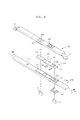
- FIG. 1 is an exploded perspective view of a secondary battery according to an embodiment of the present invention.
- FIG. 2 is an enlarged exploded perspective view of a portion of the secondary battery of FIG. 1 .
- the secondary battery includes a case 20 that houses an electrode assembly 10, a cap plate 110 that closes an open end of the case 20, and a safety device 130 that is mounted on the cap plate 110 and performs a safety operation in response to an abnormal operation, such as over-heating or flow of excess current.
- the electrode assembly 10 may preferably be formed by interposing a separator 15 between a negative electrode plate 13 and a positive electrode plate 14 to separate the negative electrode plate 13 from the positive electrode plate 14, and then winding the negative electrode plate 13, the positive electrode plate 14, and the separator 15 in a jelly-roll shape.
- Each of the negative electrode plate 13 and the positive electrode plate 14 includes an electrode active material.
- the negative electrode plate 13 and the positive electrode plate 14 may preferably respectively include first and second electrode taps 11 and 12 that allow electrical charges formed due to a chemical reaction to flow out of the electrode assembly 10.
- the electrode assembly 10 may preferably be immersed in an electrolyte (not shown) inside the case 20.
- An opening of the case 20 may preferably be shielded by the cap plate 110 after the electrode assembly 10 is placed therein.
- Contact portions of the cap plate 110 and the case 20 may preferably be firmly coupled to each other by welding, for example, laser welding.
- the first electrode tap 11 of the electrode assembly 10 may preferably contact an electrode terminal 150 that protrudes through the cap plate 110, and the second electrode tap 12 of the electrode assembly 10 may preferably contact the cap plate 110.
- the electrode terminal 150 is coupled to the cap plate 110 while being insulated from the cap plate 110, and protrudes through the cap plate 110 to electrically connect the electrode assembly 10 to the safety device 130.
- the safety device 130 may preferably be disposed on the cap plate 110 and may preferably regulate or block charge and discharge currents during malfunctioning, for example, during occurrence of overheat or excess current.
- the safety device 130 may preferably have a positive temperature coefficient (PTC) and may preferably include a fuse, a current block device, a bi-metal, or the like.
- PTC positive temperature coefficient
- the safety device 130 may preferably include a safety device body 135 and first and second leads 131 and 132 extending in opposite directions from the safety device body 135.
- the cap plate 110 may preferably have a safety vent 115 of a rupturable type so that when an inner pressure of the case 20 excesses a set point, a gas discharge path is provided.
- a circuit portion 160 may preferably be mounted on the cap plate 110.
- the circuit portion 160 may preferably include an interconnection pattern (not shown) that enables electric connection with an external device (not shown) and forms a charge and discharge current path.
- an outer connection terminal 165 for electrical connection with an external device may preferably be formed, and first and second connection members 161 and 162 may preferably be disposed on the other surface.
- the first connection member 161 may preferably contact the second lead 132 of the safety device 130, which is a negative electrode terminal.
- the first connection member 161 may preferably be coupled to the second lead 132 by welding.
- the second connection member 162 may preferably contact the cap plate 110 as a positive electrode terminal.
- the circuit portion 160 may preferably function as a protection member for preventing the occurrence of an overcharge, excess current, over-discharge, or the like, together with the safety device 130.
- An upper cover 180 for housing the circuit portion 160 may preferably be disposed on the cap plate 110.
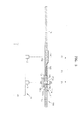
- FIG. 3 is a cross-sectional view taken along a line III-III of FIG. 2 .
- FIG. 4 is an enlarged cross-sectional view of a portion of the secondary battery of FIG. 3 .
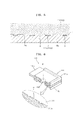
- FIG. 5 is an enlarged cross-sectional view of a portion V of FIG. 4 .
- FIGS. 6 and 7 show perspective views illustrating first and second insulating portions 111 and 112.
- the cap plate 110 is a plate formed by integrating two materials having different electrical characteristics.
- the cap plate 110 includes a conductive member 110a that forms an overall skeleton of the cap plate 110 and the first and, preferably, second insulating portions 111 and 112 that conform to the conductive member 110a.
- the first and second insulating portions 111 and 112 may preferably conform to the conductive member 110a via a series of protrusions, preferably in a complementary uneven pattern.
- a dove-tail shaped uneven pattern D may preferably be formed at an interface of the conductive member 110a and the first and second insulating portions 111 and 112 where the conductive member 110a is complementarily jointed with the first and second insulating portions 111 and 112 to prevent separation from each other.
- the cap plate 110 may preferably be formed as an insert molded product.
- the conductive member, the first insulating portion and/or the second insulating portion preferably each comprise between 1 and 20, preferably 2 and 15, and preferably between 3 and 10 protrusions in the series.
- the conductive member 110a may preferably be connected to the second electrode tap 12 of the electrode assembly 10 to form a positive electrode terminal.
- the second electrode tap 12 of the electrode assembly 10 may preferably be coupled to a lower surface of the conductive member 110a by welding, and an exposed portion of the conductive member 110a may preferably function as a positive electrode terminal.
- first and second insulating portions 111 and 112 may preferably respectively include first and second insulating portions 111 and 112 formed on first and second positions P1 and P2 on the cap plate 110.
- the first and second insulating portions 111 and 112 may preferably be formed on a surface of the conductive member 110a or may preferably pass through the conductive member 110a.
- the first insulating portion may be integrally formed as a unit.
- the second insulating portion if present is also integrally formed as a unit.
- the insulating portions comprise top and bottom portions joined by a connecting portion and all portions are integrally formed.
- integrally formed as a unit it is meant that the insulating portion is a single, seamless component, i.e. the top, bottom and connecting portions are all parts of the same single unit, these terms refer to sections of the single integral unit rather than individual parts.
- the first insulating portion 111 may preferably be formed through the conductive member 110a along a through-hole 110' of the cap plate 110.
- the present invention is not limited thereto.
- the first insulating portion 111 may preferably be formed on the conductive member 110a, not through the conductive member 110a.
- the first insulating portion 111 may preferably support the first lead 131 of the safety device 130 while insulating the first lead 131.
- the first insulating portion 111 electrically insulates the first lead 131 of the safety device 130 from the conductive member 110a and physically supports the first lead 131 of the safety device 130.
- the first insulating portion 111 prevents a short between a positive electrode and a negative electrode, that is, between the first lead 131 that is electrically connected to the first electrode tap 11 of the electrode assembly 10 and the conductive member 110a that is connected to the second electrode tap 12 of the electrode assembly 10.
- the electrode terminal 150 is inserted into the through-hole 110' of the first insulating portion 111.
- the electrode terminal 150 may preferably be inserted from a lower surface of the first insulating portion 111 and an upper portion of the electrode terminal 150 which protrudes from an upper surface of the first insulating portion 111 may preferably be processed by caulking, spinning, or rivetting to form an upper flange 150a that is widened toward a circumference of the electrode terminal 150.
- the upper flange 150a may preferably fix the electrode terminal 150 on the cap plate 110 by compression.
- the electrode terminal 150 may preferably be inserted into a through-hole 130' of the first lead 131 of the safety device 130 and the electrode terminal 150 may preferably fix the first lead 131 by compression.
- the electrode terminal 150 fixes the first lead 131 on the first insulating portion 111 by compression and forms an electrical connection with the safety device 130.
- the electrode terminal 150 may preferably be inserted into the through-hole 130' of the first lead 131 and the first lead 131 may preferably be fixed on the first insulating portion 111 by the upper flange 150a of the electrode terminal 150. In this case, welding between the electrode terminal 150 and the safety device 130 may preferably not be needed.
- the first lead 131 of the safety device 130 may preferably extend from the first position P1 where the first lead 131 is fixed on the first insulating portion 111 toward the third position P3 to be connected with the safety device body 135 disposed on the third position P3.
- the first insulating portion 111 may preferably support the electrode terminal 150 and the first lead 131 of the safety device 130 while insulating the electrode terminal 150 and the first lead 131, thereby preventing an electrical short between the electrode terminal 150 and the first lead 131 and the conductive member 110a.
- the first insulating portion 111 may preferably form the through-hole 110' of the cap plate 110, and may preferably extend toward a surrounding of the through-hole 110' and support the electrode terminal 150 and the first lead 131 while insulating the electrode terminal 150 and the first lead 131.
- the first insulating portion 111 extends along the through-hole 110', and upper and lower ends 111a and 111b of the first insulating portion 111 may preferably extend in a surface direction of the cap plate 110.
- first insulating portion 111 may preferably insulate the first lead 131 and the lower end 111b may preferably insulate a lower flange 150b of the electrode terminal 150.
- a portion of the first insulating portion 111 disposed in the through-hole 110' may preferably be integrated with the upper and lower ends 111a and 111b.
- the first insulating portion 111 may preferably have a gasket function for sealing the through-hole 110' of the cap plate 110. That is, the first insulating portion 111 seals the surrounding of the through-hole 110' while surrounding the electrode terminal 150 to prevent leakage of an electrolyte or permeation of external impurities through the through-hole 110'.
- the electrode terminal 150 may preferably be forcedly inserted into the through-hole 110' of the first insulating portion 111, and if the first insulating portion 111 is formed of a resin-based material, the first insulating portion 111 may preferably firmly contact the circumference of the electrode terminal 150.
- the first insulating portion 111 may preferably conform to and may preferably be integrated with the conductive member 110a, and at the interface of the first insulating portion 111 and the conductive member 110a, the dove-tail shaped uneven pattern D may preferably form a stopper structure for preventing separation of the first insulating portion 111 and the conductive member 110a, thereby allowing the first insulating portion 111 and the conductive member 110a to be firmly coupled to each other.
- the dove-tail shaped pattern D may preferably form a stopper structure for preventing separation of the first insulating portion 111 and the conductive member 110a at the interface therebetween.
- protrusions 111 p and 110ap of the first insulating portion 111 and the conductive member 110a may preferably have gradually increasing widths t1 and t2 in their protruding directions.
- t1 is less than t2
- preferably t1 is between 15% and 75% of t2
- preferably t1 is between 20% and 50% of t2.
- the electrode terminal 150 may preferably effectively fix the first lead 131 on the first insulating portion 111.
- a position (first position P1) of the electrode terminal 150 may preferably be a position (offset distance L) eccentric with respect to a central portion (second position P2) of the cap plate 110.
- an installation space on the cap plate 110 may preferably be effectively used, and for example, electrical devices for controlling charge and discharge operations may preferably be compactly installable.
- a negative electrode terminal may preferably be formable on the central portion (second position P2) of the cap plate 110 by using the safety device 130 that extends from the first position P1 to the central portion (second position P2). That is, the safety device 130 may preferably extend from the first position P1 to the central portion (second position P2) of the cap plate 110 so that the second lead 132 may preferably form a negative electrode terminal on the central portion (second position P2) of the cap plate 110.
- the electrode terminal 150 may preferably allow the electrode assembly 10 and the safety device 130 disposed on opposite sides of the cap plate 110 to be electrically connected to each other.
- the electrode terminal 150 may preferably be electrically connected to the first lead 131 of the safety device 130 through the upper flange 150a and may preferably be electrically connected to the electrode assembly 10 through the lower flange 150b.
- the lower flange 150b of the electrode terminal 150 may preferably have a wider area than the upper flange 150a and may preferably provide a wide area for welding with the electrode assembly 10. That is, a width or radius W2 of the lower flange 150b may preferably be wider than width or radius W1 of the upper flange 150a. Due to the wider area of the lower flange 150b than the upper flange 150a, there is no need to use a terminal plate for increasing a welding area between the electrode terminal 150 and the electrode assembly 10. In preferred embodiments of the present invention W1 is between 15% and 60% of W2, preferably between 20% and 50%, preferably between 30% and 45%.
- the second insulating portion 112 supports the second lead 132 of the safety device 130 while insulating the second lead 132.
- the second insulating portion 112 may preferably be formed on the second position P2 of the cap plate 110, and for example, the central portion of the cap plate 110.
- the second insulating portion 112 may preferably be formed on the surface of the conductive member 110a that forms a skeleton of the cap plate 110.
- the second insulating portion 112 may preferably conform to and may preferably be integrated with the conductive member 110a, and at an interface between the second insulating portion 112 and the conductive member 110a, the dove-tail shaped uneven pattern D may preferably form a stopper structure for preventing separation of the second insulating portion 112 and the conductive member 110a.
- the dove-tail shaped pattern D forms a stopper structure for preventing separation of the second insulating portion 112 and the conductive member 110a at the interface therebetween.
- protrusions 112p and 110ap of the second insulating portion 112 and the conductive member 110a may preferably have gradually increasing widths t1 and t2 in their protruding directions. As discussed above, preferably t1 is less than t2, preferably t1 is between 15% and 75% of t2, and preferably t1 is between 20% and 50% of t2.
- the second lead 132 of the second insulating portion 112 may preferably be electrically connected to the first electrode tap 11 of the electrode assembly 10 through the electrode terminal 150 and may preferably form a negative electrode terminal. That is, the second lead 132 of the safety device 130 may preferably be exposed on the second insulating portion 112 to form a negative electrode terminal.
- the cap plate 110 may preferably be formed as an insert molded product that is formed by integrating the conductive member 110a forming a skeleton of the cap plate 110 with the first and second insulating portions 111 and 112 conforming to the conductive member 110a.
- the conductive member 110a is temporally fixed at a predetermined position inside a mold frame (not shown) and then, a molten molding resin is loaded into the mold frame to form the cap plate 110 that includes the conductive member 110a and the first and second insulating portions 111 and 112 which are all integrated as one body.
- the first and second insulating portions 111 and 112 may preferably be simultaneously formed of the same material.
- the first and second insulating portions 111 and 112 may preferably be formed of a resin-based material.
- the conductive member 110a functions as a positive electrode terminal. Also, due to the integration of the conductive member 110a with the first and second insulating portions 111 and 112 that support the electrode terminal 150 and the safety device 130 which have polities opposite to that of the conductive member 110a while insulating the electrode terminal 150 and the safety device 130, a conventional process for disposing a separate insulating material on the cap plate 110 is not required. Also, due to the formation of a unit module in which the conductive member 110a is integrated with the first and second insulating portions 111 and 112, the whole assembly process for a secondary battery may be simplified.
- the safety device 130 incudes the first and second leads 131 and 132 supported by the first and second insulating portions 111 and 112, and the safety device body 135 interposed between the first and second leads 131 and 132.
- the safety device body 135 may preferably be disposed in a recess R between the first and second insulating portions 111 and 112. That is, because the safety device body 135 is disposed on a portion of the conductive member 110a on which the first and second insulating portions 111 and 112 are not formed, the safety device body 135 precisely senses an inner temperature of the secondary battery.
- a heat transmission member 120 may preferably be interposed between the safety device body 135 and the cap plate 110 (in particular, the conductive member 110a). In an embodiment, the heat transmission member 120 may preferably be interposed between the safety device body 135 and the cap plate 110 to allow the safety device body 135 and the cap plate 110 to thermally contact each other.
- the heat transmission member 120 may preferably be formed of a flexible and thermally conductive material so that the heat transmission member 120 is smoothly deformed between the safety device body 135 and the cap plate 110 and firmly contacts the safety device body 135 and the cap plate 110.
- the heat transmission member 120 may preferably include an adhesive material for firmly contacting the safety device body 135 and the cap plate 110.
- the heat transmission member 120 may preferably be formed of a composite material, such as a mix sheet containing thermally conductive particles.
- the heat transmission member 120 may preferably be formed by application of thermally conductive silicone.
- thermally conductive silicone is applied at a position on which the safety device body 135 is to be mounted, and then, another heat transmission member having a sheet shape is deposited thereon.
- insulating coating or an insulating film may preferably be formed on a surface of the safety device body 135, and these insulating materials may preferably be integrated as an outer material with the safety device body 135.
Landscapes
- Chemical & Material Sciences (AREA)
- Chemical Kinetics & Catalysis (AREA)
- Electrochemistry (AREA)
- General Chemical & Material Sciences (AREA)
- Connection Of Batteries Or Terminals (AREA)
- Sealing Battery Cases Or Jackets (AREA)
Applications Claiming Priority (2)
| Application Number | Priority Date | Filing Date | Title |
|---|---|---|---|
| US201161546416P | 2011-10-12 | 2011-10-12 | |
| US13/475,838 US9331312B2 (en) | 2011-10-12 | 2012-05-18 | Secondary battery |
Publications (2)
| Publication Number | Publication Date |
|---|---|
| EP2581959A2 true EP2581959A2 (de) | 2013-04-17 |
| EP2581959A3 EP2581959A3 (de) | 2014-01-15 |
Family
ID=46516611
Family Applications (1)
| Application Number | Title | Priority Date | Filing Date |
|---|---|---|---|
| EP12177033.3A Withdrawn EP2581959A3 (de) | 2011-10-12 | 2012-07-19 | Sekundärbatterie |
Country Status (4)
| Country | Link |
|---|---|
| US (1) | US9331312B2 (de) |
| EP (1) | EP2581959A3 (de) |
| KR (1) | KR101352976B1 (de) |
| CN (1) | CN103117363A (de) |
Families Citing this family (14)
| Publication number | Priority date | Publication date | Assignee | Title |
|---|---|---|---|---|
| KR101985760B1 (ko) * | 2013-01-17 | 2019-06-04 | 삼성에스디아이 주식회사 | 이차전지 |
| CN105655535B (zh) * | 2014-11-24 | 2018-10-09 | 瑞侃电子(上海)有限公司 | 热保护组件及其制造方法 |
| KR102323949B1 (ko) * | 2015-03-03 | 2021-11-08 | 삼성에스디아이 주식회사 | 상부 커버를 갖는 이차 전지 |
| JP6773942B2 (ja) * | 2016-03-07 | 2020-10-21 | エリーパワー株式会社 | 端子付き電池蓋及び密閉型電池 |
| CN205657096U (zh) * | 2016-05-16 | 2016-10-19 | 宁德时代新能源科技股份有限公司 | 二次电池顶盖 |
| KR102257680B1 (ko) * | 2016-09-07 | 2021-05-28 | 삼성에스디아이 주식회사 | 이차전지 |
| CN106684269A (zh) * | 2017-01-19 | 2017-05-17 | 佛山市康荣精细陶瓷有限公司 | 一种锂电池的盖板结构及其制作方法 |
| EP3385997A1 (de) * | 2017-04-04 | 2018-10-10 | Lithium Energy and Power GmbH & Co. KG | Sekundärzelle und verfahren zur herstellung einer sekundärzelle |
| CN109428023B (zh) * | 2017-08-31 | 2024-04-16 | 宁德时代新能源科技股份有限公司 | 固定架、电池单元以及电池模组 |
| CN110176558B (zh) | 2019-04-09 | 2024-04-19 | 宁德时代新能源科技股份有限公司 | 二次电池顶盖组件及二次电池 |
| KR102876711B1 (ko) * | 2019-07-24 | 2025-10-27 | 에스케이온 주식회사 | 배터리 케이스 |
| US20220209347A1 (en) * | 2020-12-31 | 2022-06-30 | Samsung Sdi Co., Ltd. | Battery module |
| EP4312302A1 (de) * | 2022-07-25 | 2024-01-31 | Prime Planet Energy & Solutions, Inc. | Batterie |
| KR20240140468A (ko) * | 2023-03-17 | 2024-09-24 | 삼성에스디아이 주식회사 | 이차 전지의 외부 터미널 연결 구조 |
Family Cites Families (15)
| Publication number | Priority date | Publication date | Assignee | Title |
|---|---|---|---|---|
| KR100274939B1 (ko) | 1998-08-25 | 2000-12-15 | 장용균 | 리튬전지의 전극단자 실링장치 |
| JP2002343315A (ja) * | 2001-05-10 | 2002-11-29 | Alps Electric Co Ltd | 電池蓋ユニット |
| US20040170887A1 (en) | 2001-08-07 | 2004-09-02 | Kenjin Masumoto | Non-aqueous electrolytic secondary battery |
| KR100591430B1 (ko) | 2004-05-19 | 2006-06-22 | 삼성에스디아이 주식회사 | 이차전지 |
| KR100561308B1 (ko) * | 2004-05-31 | 2006-03-15 | 삼성에스디아이 주식회사 | 이차전지 |
| KR100696791B1 (ko) | 2005-04-27 | 2007-03-19 | 삼성에스디아이 주식회사 | 캡 조립체와 이를 구비하는 리튬이온 이차전지 |
| KR100686800B1 (ko) | 2005-07-26 | 2007-02-26 | 삼성에스디아이 주식회사 | 이차 전지 |
| KR101022634B1 (ko) | 2006-02-20 | 2011-03-22 | 주식회사 엘지화학 | 개선된 구조의 캡 어셈블리 및 이를 포함하는 이차전지 |
| JP2008016190A (ja) | 2006-06-30 | 2008-01-24 | Sanyo Electric Co Ltd | パック電池 |
| JP2008159395A (ja) | 2006-12-22 | 2008-07-10 | Sanyo Electric Co Ltd | パック電池 |
| KR101087046B1 (ko) | 2007-11-29 | 2011-11-25 | 주식회사 엘지화학 | Ptc 소자가 장착된 탑 캡을 포함하는 전지팩 |
| JP5345633B2 (ja) * | 2007-11-29 | 2013-11-20 | エルジー・ケム・リミテッド | 緻密な構造の二次バッテリーパック |
| KR100971339B1 (ko) | 2008-04-18 | 2010-07-20 | 삼성에스디아이 주식회사 | 배터리 팩 |
| KR101002518B1 (ko) | 2008-06-23 | 2010-12-17 | 삼성에스디아이 주식회사 | 이차 전지 |
| CN101752611B (zh) | 2008-12-04 | 2012-11-28 | 深圳市比克电池有限公司 | 锂电池 |
-
2012
- 2012-05-18 US US13/475,838 patent/US9331312B2/en not_active Expired - Fee Related
- 2012-07-19 KR KR1020120078508A patent/KR101352976B1/ko not_active Expired - Fee Related
- 2012-07-19 EP EP12177033.3A patent/EP2581959A3/de not_active Withdrawn
- 2012-07-24 CN CN2012102587336A patent/CN103117363A/zh active Pending
Non-Patent Citations (1)
| Title |
|---|
| None |
Also Published As
| Publication number | Publication date |
|---|---|
| KR101352976B1 (ko) | 2014-01-22 |
| US20130095364A1 (en) | 2013-04-18 |
| KR20130039655A (ko) | 2013-04-22 |
| US9331312B2 (en) | 2016-05-03 |
| EP2581959A3 (de) | 2014-01-15 |
| CN103117363A (zh) | 2013-05-22 |
Similar Documents
| Publication | Publication Date | Title |
|---|---|---|
| EP2581959A2 (de) | Sekundärbatterie | |
| EP2058876B1 (de) | Sekundärbatterie und Verfahren zu deren Herstellung | |
| CN100375318C (zh) | 二次电池 | |
| US8592066B2 (en) | Battery assembly | |
| JP5166462B2 (ja) | バッテリパック | |
| BRPI0820355B1 (pt) | pacote de bateria secundária de estrutura compacta | |
| JP2005203366A (ja) | 二次電池 | |
| EP2581961B1 (de) | Sekundärbatterie | |
| US20110281141A1 (en) | Battery pack | |
| US20130089759A1 (en) | Rechargeable battery | |
| JP4558671B2 (ja) | 二次電池 | |
| US12080918B2 (en) | Secondary battery and secondary battery assembly | |
| EP2378591B1 (de) | Sekundärbatterie | |
| JP2005203371A (ja) | 二次電池 | |
| US8252453B2 (en) | Secondary battery | |
| EP2905821B1 (de) | Wiederaufladbares Batteriepaket | |
| US9293743B2 (en) | Battery pack | |
| JP5258813B2 (ja) | バッテリパック | |
| JP2008016190A (ja) | パック電池 | |
| JP6830771B2 (ja) | 二次電池 | |
| KR100788558B1 (ko) | 팩 전지 | |
| KR101264519B1 (ko) | 이차 전지 및 그 제조 방법 | |
| JP2008159395A (ja) | パック電池 |
Legal Events
| Date | Code | Title | Description |
|---|---|---|---|
| PUAI | Public reference made under article 153(3) epc to a published international application that has entered the european phase |
Free format text: ORIGINAL CODE: 0009012 |
|
| AK | Designated contracting states |
Kind code of ref document: A2 Designated state(s): AL AT BE BG CH CY CZ DE DK EE ES FI FR GB GR HR HU IE IS IT LI LT LU LV MC MK MT NL NO PL PT RO RS SE SI SK SM TR |
|
| AX | Request for extension of the european patent |
Extension state: BA ME |
|
| 17P | Request for examination filed |
Effective date: 20130318 |
|
| PUAL | Search report despatched |
Free format text: ORIGINAL CODE: 0009013 |
|
| AK | Designated contracting states |
Kind code of ref document: A3 Designated state(s): AL AT BE BG CH CY CZ DE DK EE ES FI FR GB GR HR HU IE IS IT LI LT LU LV MC MK MT NL NO PL PT RO RS SE SI SK SM TR |
|
| AX | Request for extension of the european patent |
Extension state: BA ME |
|
| RIC1 | Information provided on ipc code assigned before grant |
Ipc: H01M 2/02 20060101AFI20131211BHEP Ipc: H01M 2/34 20060101ALI20131211BHEP Ipc: H01M 2/04 20060101ALI20131211BHEP |
|
| 17Q | First examination report despatched |
Effective date: 20150910 |
|
| GRAP | Despatch of communication of intention to grant a patent |
Free format text: ORIGINAL CODE: EPIDOSNIGR1 |
|
| INTG | Intention to grant announced |
Effective date: 20160329 |
|
| STAA | Information on the status of an ep patent application or granted ep patent |
Free format text: STATUS: THE APPLICATION IS DEEMED TO BE WITHDRAWN |
|
| 18D | Application deemed to be withdrawn |
Effective date: 20160809 |