EP2581992B1 - Elektrische Verbindungsklemme - Google Patents
Elektrische Verbindungsklemme Download PDFInfo
- Publication number
- EP2581992B1 EP2581992B1 EP12184977.2A EP12184977A EP2581992B1 EP 2581992 B1 EP2581992 B1 EP 2581992B1 EP 12184977 A EP12184977 A EP 12184977A EP 2581992 B1 EP2581992 B1 EP 2581992B1
- Authority
- EP
- European Patent Office
- Prior art keywords
- electrical connection
- plug connector
- connection part
- casing
- connector according
- Prior art date
- Legal status (The legal status is an assumption and is not a legal conclusion. Google has not performed a legal analysis and makes no representation as to the accuracy of the status listed.)
- Not-in-force
Links
Images

Classifications
-
- H—ELECTRICITY
- H01—ELECTRIC ELEMENTS
- H01R—ELECTRICALLY-CONDUCTIVE CONNECTIONS; STRUCTURAL ASSOCIATIONS OF A PLURALITY OF MUTUALLY-INSULATED ELECTRICAL CONNECTING ELEMENTS; COUPLING DEVICES; CURRENT COLLECTORS
- H01R13/00—Details of coupling devices of the kinds covered by groups H01R12/70 or H01R24/00 - H01R33/00
- H01R13/46—Bases; Cases
- H01R13/52—Dustproof, splashproof, drip-proof, waterproof, or flameproof cases
- H01R13/527—Flameproof cases
-
- H—ELECTRICITY
- H01—ELECTRIC ELEMENTS
- H01R—ELECTRICALLY-CONDUCTIVE CONNECTIONS; STRUCTURAL ASSOCIATIONS OF A PLURALITY OF MUTUALLY-INSULATED ELECTRICAL CONNECTING ELEMENTS; COUPLING DEVICES; CURRENT COLLECTORS
- H01R4/00—Electrically-conductive connections between two or more conductive members in direct contact, i.e. touching one another; Means for effecting or maintaining such contact; Electrically-conductive connections having two or more spaced connecting locations for conductors and using contact members penetrating insulation
- H01R4/28—Clamped connections, spring connections
- H01R4/48—Clamped connections, spring connections utilising a spring, clip, or other resilient member
- H01R4/4809—Clamped connections, spring connections utilising a spring, clip, or other resilient member using a leaf spring to bias the conductor toward the busbar
- H01R4/484—Spring housing details
-
- H—ELECTRICITY
- H01—ELECTRIC ELEMENTS
- H01R—ELECTRICALLY-CONDUCTIVE CONNECTIONS; STRUCTURAL ASSOCIATIONS OF A PLURALITY OF MUTUALLY-INSULATED ELECTRICAL CONNECTING ELEMENTS; COUPLING DEVICES; CURRENT COLLECTORS
- H01R4/00—Electrically-conductive connections between two or more conductive members in direct contact, i.e. touching one another; Means for effecting or maintaining such contact; Electrically-conductive connections having two or more spaced connecting locations for conductors and using contact members penetrating insulation
- H01R4/28—Clamped connections, spring connections
- H01R4/48—Clamped connections, spring connections utilising a spring, clip, or other resilient member
- H01R4/4809—Clamped connections, spring connections utilising a spring, clip, or other resilient member using a leaf spring to bias the conductor toward the busbar
- H01R4/48185—Clamped connections, spring connections utilising a spring, clip, or other resilient member using a leaf spring to bias the conductor toward the busbar adapted for axial insertion of a wire end
- H01R4/4819—Clamped connections, spring connections utilising a spring, clip, or other resilient member using a leaf spring to bias the conductor toward the busbar adapted for axial insertion of a wire end the spring shape allowing insertion of the conductor end when the spring is unbiased
- H01R4/4821—Single-blade spring
-
- H—ELECTRICITY
- H01—ELECTRIC ELEMENTS
- H01R—ELECTRICALLY-CONDUCTIVE CONNECTIONS; STRUCTURAL ASSOCIATIONS OF A PLURALITY OF MUTUALLY-INSULATED ELECTRICAL CONNECTING ELEMENTS; COUPLING DEVICES; CURRENT COLLECTORS
- H01R9/00—Structural associations of a plurality of mutually-insulated electrical connecting elements, e.g. terminal strips or terminal blocks; Terminals or binding posts mounted upon a base or in a case; Bases therefor
- H01R9/11—End pieces for multiconductor cables supported by the cable and for facilitating connections to other conductive members, e.g. for liquid cooled welding cables
Definitions
- the invention relates to an electrical connection terminal, suitable for use at higher, about the temperatures required for a fire protection application, comprising an electrical connection part for holding together to be connected electrical conductors by a terminal closure, and the temperature requirements sufficient, the connection part enclosing coat.
- connection terminals are required for connecting electrical conductors with each other, which must withstand certain temperature stresses. These temperature stresses may be those caused by the operation of an electrical load, such as a lamp.
- connection terminals are used so that electrical installations, such as building installations meet the fire protection requirements. According to the fire protection requirements, it is necessary that certain electrical installations, such as communication installations must remain functional even in case of fire, at least for a certain period of time.
- ceramic terminals which are often used as terminal blocks, sitting on a mounting rail.
- These terminals are luster terminals with a ceramic housing, which surrounds a tubular profile of an electrically conductive material as an electrical connection part. In this electrical connection part one or two threaded holes are introduced. There are clamping screws in these. The ends of electrical conductors to be joined together are clamped by means of clamping screws in the tubular profile and are thus held by a terminal closure in the electrical connection part.
- the ceramic housing forms the coat sufficient for the temperature requirements.
- This jacket also forms the electrical insulation to the outside and in the formation of the connection terminal as a terminal block the insulation between adjacent poles.
- the WO 01/09990 shows a method of making a connection to an electrical cable.
- an outer sheath of the cable is removed in a section and stripped the individual wires of the cable. Subsequently, these are conductively connected to a plug part.
- the compound thus created is placed in a mold and encapsulated overall with a plastic material to form an insulating plug housing.
- the sheath of the cable and the connector housing may be made of a refractory or fire-retardant material.
- the plug part can be accommodated in a ceramic insert, which is poured into the overall plastic material in the mold.
- the JP 2009/218141 discloses an electrical connection terminal intended to provide improved protection against withdrawal of an inserted electrical conductor.
- the clamp comprises a housing body and a cover part closing the latter, which has openings for introducing conductors.
- a metallic fitting is installed, which has a front wall, a bottom plate and a rear wall.
- spring terminals are formed, which are deflected when inserting a conductor and clamp it so. Fire safety of the connection terminal is not referred to.
- the invention is therefore the object of developing an electrical connection terminal of the type mentioned in such a way that it not only withstand the requirements for use at higher temperatures, especially those required for a fire protection applications, but that in this Above all, the effort to create an electrical connection between two electrical conductors is simplified.
- an electrical connection terminal mentioned above in which the electrical connection part is designed as a spring clamp and sitting in a plastic housing, which plastic housing is positively arranged in the shell of a temperature-resistant material, wherein the electrical connection part with its plastic housing of the temperature-resistant Sheath is framed such that the electrical connection part is held captive even in the jacket when the plastic housing is destroyed or burned due to a temperature effect.
- the electrical connection part is designed as a spring-type terminal, often also addressed as a plug-in terminal.
- the connection of an electrical conductor to this electrical connection part takes place without tools, namely solely by inserting the stripped conductor end.
- This electrical connection part is seated in a plastic housing, through which the spring-loaded terminal is typically also electrically isolated at the same time.
- the plastic housing, which includes the electrical connection part is arranged in a form-fitting manner in the temperature-resistant jacket, for example a ceramic shell.
- the arrangement of the spring clamp with its plastic housing in the temperature-resistant jacket is designed such that the electrical connection part is also held captive in the jacket when the plastic part surrounding the connecting part destroyed or - as in a fire the rule - burned after a certain time of the fire and therefore no longer available is.
- the electrically conductive components are sufficiently isolated, so that in several cases installed in a junction box connection terminals in such a case, the risk of short circuit is effectively avoided.
- such a connection terminal can be used even if the risk of damage, destruction or a change in the material condition of a plastic housing within the environment of the arrangement of the connection terminal can not be excluded, as is the case, for example, when used in areas of higher temperature environment.
- the plastic housing which becomes brittle due to the effect of temperature, remains between the electrical connection part and the temperature-resistant sheath, held by the sheath, and effectively forms the electrical insulator even in the case of such a state change.
- connection terminal for the production of the claimed connection terminal commercial spring terminals (plug-in terminals) can be used to which the temperature-resistant jacket is attached. This is done in accordance with a preferred embodiment by encapsulating such a spring clamp with the intended for the formation of the temperature-resistant shell material, such as a ceramic material. It is understood that in the course of this casting process at least one conductor receptacle of the housing remains free. The same applies to the rear of the conductor mounting side opposite back mostly test openings. Since such spring-type terminals are mass-produced especially in a multi-pole design, they form a cost-effective starting product from which the above-described connection terminals can be made.
- spring-type terminals are mass-produced especially in a multi-pole design, they form a cost-effective starting product from which the above-described connection terminals can be made.
- a latch is provided on the conductor mounting side of the spring-loaded terminal, which extends transversely to the row of the poles and is integrally formed on the opposite side walls of the jacket.
- Such a configuration lends itself to a multi-pole spring-type terminal, wherein one of the poles is no longer usable by the bolt for the electrical connection. It is understood that in such a configuration, a plurality of bars can be provided. If only such a bolt is provided, it is advisable to arrange this centered or mittignah with respect to the ranking of the poles.
- the typically multi-pole spring-loaded terminal for forming the temperature-resistant shell of ceramic material can be encapsulated, which then surrounds the plastic housing hardens around.
- one or more connecting members may be formed on the temperature-resistant jacket of the connecting terminal. These may serve the purpose of connecting individual connection terminals of this type with each other and / or fix them in a junction box.
- the design of the connecting members as part of the temperature-resistant shell has the consequence that even in a region of higher temperature, such as in a fire, the mechanical connection of the spring clamps is maintained with each other. This requires in such links, which are connected to an additional link that this also meets the temperature requirements.
- the connecting members may be projections formed on the jacket with an opening. Depending on the configuration of the same and of the extension, the opening may, for example, engage a screw, a pin or a clamp for producing the connection.
- An electrical connection terminal 1 comprises a heat-resistant ceramic jacket 2.
- the jacket 2 is made of a ceramic material which is not only heat-resistant but also has electrically insulating properties.
- a commercial spring cage terminal 3 which is designed in the illustrated embodiment 5-pin.
- FIG. 1 shows the connection terminal 1 with respect to its conductor mounting side 4.
- the conductor mounting side 4 is the side at which electrical conductors are inserted into the connection terminal 1 with its stripped end for the purpose of contacting. Therefore, the conductor mounting side 4 is open with respect to the spring clamp 3 disposed in the sheath 2. Consequently, at least some of the five conductor receptacles of the spring-loaded terminal 3 are accessible and not covered by the jacket 2.
- connection terminal 1 can therefore be used as a 4-pin connection terminal.
- the spring-loaded terminal 3 is a commercially available terminal, also referred to as a plug-in terminal. This comprises a clamping rail made of conductive metal, each pole being associated with a spring clip. For this reason, the four usable poles of the connection terminal 1 are assigned one and the same electrical conductor and can therefore be referred to in principle as connection points. Nonetheless, as is customary in common usage, these will continue to be referred to below as poles.
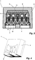
- the structure of the spring clamp 1 is clear from the longitudinal section of FIG. 3 ,
- the spring clamp 3 comprises as electrical connection part a clamping rail 8, which is constructed in the illustrated embodiment, as described above, 5-pin. For this reason, each pole has a spring terminal 9.
- the clamping rail 8 with its spring terminals 9 is inserted into a plastic housing 10.
- the plastic housing 10 is made in two parts in the illustrated embodiment and comprises a first housing part 11 as a receptacle for the clamping rail 8 and a second Housing part 12 which fixes the inserted in the first housing part 11 clamping rail 8 therein in the manner of a closure body.
- the plastic housing 10 has electrically insulating properties, as is the case for commercially available spring-type terminals. Enclosed is this spring clamp 3 in the ceramic shell 2.
- FIG. 3 From the longitudinal section of FIG. 3 clearly shows the arrangement of the bolt 5 can be seen that crosses the conductor mounting side 4 transverse to the order of the poles.
- the ceramic shell 2 is a casting that has been cast around the spring clamp 3 around. In this case, a mold has been used, through which the openings remain in the conductor mounting side 4, or the latch 5 is formed.
- the side walls of the ceramic shell 2 are inclined at a small angle to each other in the direction of the back 6, which slope serves as a draft angle.
- the presentation of the FIG. 3 makes it clear that the electrical connection terminal 1 can be used as a 4-pin plug-in terminal.
- the bolt 5 with its extension 6 serves the purpose that the arranged in the plastic housing 10 clamping rail 8 is still form-fitting inside the chamber formed by the ceramic shell 2, when the plastic housing 10 is no longer available.
- the clamping rail 8 remains made of metal with its spring terminals 9. In such a state of the connection terminal 1, the electrically conductive clamping rail 8 is still taken captive in the ceramic shell 2 with their spring terminals 9. This means that even in the case of fire, in which the electrically insulating plastic housing 10 has been destroyed, the electrical conductors are still not exposed, whereby a risk of short circuit is effectively avoided.
- connection terminal 1 Since in the connection terminal 1, a commercially available spring terminal 3 is used with a clamping rail 8 as an electrical connection part, the connection of electrical conductors is without tools and readily feasible. Finally, the stripped conductor ends - whether cables or wires - must only be inserted into the conductor receptacles of the connection terminal 1 and inserted into the respective spring terminal 9. These act under bias standing on the inserted conductor end, in the manner of a barb, wherein the force acting on the respective conductor clamping force increases at a voltage applied to the conductor mechanical tension.
- the ceramic shell 2 has been created by means of a casting. This manufacturing method lends itself to, if desired, to form the ceramic shell 2 connecting members. Such links may serve the purpose of interconnecting individual connection terminals. This can take place in the transverse direction and / or also in the longitudinal direction thereof.
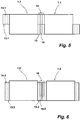
- FIG. 5 shows in a first embodiment, a connection terminal 1.1, at its opposite transverse sides of the ceramic shell 2 each carries a connection extension 13, 13.1 as a link.
- the connection extensions 13, 13.1 each have an opening 14 or 14.1.
- the connection extensions 13, 13.1 are arranged point-symmetrically with respect to the connection terminal 1.1.
- the connection extension 13 is formed in the illustrated embodiment in the alignment of the back 6 to the ceramic shell 2.1 and extends to the middle of the height of the shell 2.1, while the connection extension 13.1 is provided with its one side in alignment with the conductor mounting side 4 and also extends with respect to the height to the center of the ceramic shell 2.1.
- several such connection terminals 1.1 are queued to each other.
- a metal pin 15 To fix the connection terminals 1.1 with each other is a metal pin 15. Since this is fire resistant, the mechanical juxtaposition of the connection terminals 1.1 is maintained even in case of fire.
- FIG. 6 shows two more, interconnected connection terminals 1.2. These each have an over the entire height extending connection extension 13.2 and 13.3. Also introduced is an opening 14.2, 14.3 in the connection extensions 13.2, 13.3. Two such, with their transverse sides adjacent connection terminals 1.2 can, as in FIG. 6 shown to be held together with a connection clip 16.
- the connecting bracket 16 is made of metal, which is why this connection is maintained in case of fire.
- connection terminals can also carry such a connecting terminal or only on its longitudinal walls, so that a multiplicity of such connecting terminals can be connected to one another. Since, in principle, such connection terminals only need to be accessible from one side, the space available in a connection box can be largely completely utilized by such interconnected connection terminals.
Landscapes
- Connector Housings Or Holding Contact Members (AREA)
- Connections Arranged To Contact A Plurality Of Conductors (AREA)
- Cable Accessories (AREA)
- Details Of Connecting Devices For Male And Female Coupling (AREA)
Description
- Die Erfindung betrifft eine elektrische Verbindungsklemme, geeignet für einen Einsatz bei höheren, etwa den für eine Brandschutzanwendung geforderten Temperaturen, umfassend ein elektrisches Verbindungsteil zum Halten von miteinander zu verbindenden elektrischen Leitern durch einen Klemmschluss, und einen den Temperaturanforderungen genügenden, das Verbindungsteil einfassenden Mantel.
- Für zahlreiche Anwendungen werden elektrische Verbindungsklemmen zum Verbinden von elektrischen Leitern miteinander benötigt, die gewissen Temperaturbeanspruchungen standhalten müssen. Bei diesen Temperaturbeanspruchungen kann es sich um solche handeln, die durch den Betrieb eines elektrischen Verbrauchers, beispielsweise einer Leuchte entstehen. Darüber hinaus werden derartige Verbindungsklemmen eingesetzt, damit elektrische Installationen, beispielsweise Gebäudeinstallationen den Brandschutzanforderungen genügen. Gemäß den Brandschutzanforderungen ist es erforderlich, dass bestimmte elektrische Installationen, wie etwa Kommunikationsinstallationen auch im Brandfalle zumindest über einen gewissen Zeitraum hinweg funktionstüchtig bleiben müssen. Diesen Anforderungen genügen Keramikklemmen, die oftmals als Reihenklemmen, auf einer Montageschiene sitzend, eingesetzt werden. Bei diesen Klemmen handelt es sich um Lüsterklemmen mit einem Keramikgehäuse, welches ein rohrförmiges Profil aus einem stromleitenden Material als elektrisches Verbindungsteil umgibt. In dieses elektrische Verbindungsteil sind ein oder zwei Gewindebohrungen eingebracht. In diesen sitzen Klemmschrauben. Die miteinander zu verbindenden Enden elektrischer Leiter werden mittels Klemmschrauben in dem rohrförmigen Profil festgeklemmt und sind damit durch einen Klemmschluss in dem elektrischen Verbindungsteil gehalten.
- Bei diesen elektrischen Verbindungsklemmen bildet das Keramikgehäuse den den Temperaturanforderungen genügenden Mantel. Dieser Mantel bildet zugleich die elektrische Isolierung nach außen hin und bei Ausbildung der Verbindungsklemme als Reihenklemme die Isolierung zwischen benachbarten Polen.
- Derartige elektrische Verbindungsklemmen genügen den an eine Brandschutzanwendung gestellten Anforderungen. Allerdings ist der Aufwand zum Verbinden elektrischer Leiter nicht unbeträchtlich, vor allem dann, wenn innerhalb einer Anschlussdose eine Vielzahl von Leiter miteinander zu verbinden sind. Dieses ist jedoch gerade typisch für Verbindungen von Kommunikationsinstallationen.
- Die
WO 01/09990 - Die
JP 2009/218141 - Das Dokument
EP 2 263 757 A1 offenbart eine elektrische Verbindungsklemme gemäss dem Oberbegriff des Anspruchs 1. - Ausgehend von diesem diskutierten Stand der Technik liegt der Erfindung daher die Aufgabe zugrunde, eine elektrische Verbindungsklemme der eingangs genannten Art dergestalt weiterzubilden, dass diese nicht nur die für einen Einsatz bei höheren Temperaturen, insbesondere den für eine Brandschutzanwendung geforderten Temperaturen standhält, sondern dass bei dieser vor allem der Aufwand zum Erstellen einer elektrischen Verbindung zwischen zwei elektrischen Leitern vereinfacht ist.
- Gelöst wird diese Aufgabe erfindungsgemäß durch eine eingangs genannte elektrische Verbindungsklemme, bei der das elektrische Verbindungsteil als Federzugklemme ausgeführt ist und in einem Kunststoffgehäuse sitzt, welches Kunststoffgehäuse formschlüssig in dem Mantel aus einem temperaturbeständigen Material angeordnet ist, wobei das elektrische Verbindungsteil mit seinem Kunststoffgehäuse von dem temperaturbeständigen Mantel dergestalt eingefasst ist, dass das elektrische Verbindungsteil auch dann unverlierbar in dem Mantel gehalten ist, wenn das Kunststoffgehäuse aufgrund einer Temperatureinwirkung zerstört oder verbrannt ist.
- Bei dieser elektrischen Verbindungsklemme ist das elektrische Verbindungsteil als Federzugklemme, oftmals auch als Steckklemme angesprochen, ausgeführt. Damit erfolgt der Anschluss eines elektrischen Leiters an dieses elektrische Verbindungsteil werkzeuglos, nämlich allein durch Einstecken des abisolierten Leiterendes. Dieses elektrische Verbindungsteil sitzt in einem Kunststoffgehäuse, durch welches die Federzugklemme typischerweise auch gleichzeitig elektrisch isoliert ist. Von Besonderheit bei der beanspruchten Verbindungsklemme ist, dass das Kunststoffgehäuse, welches das elektrische Verbindungsteil beinhaltet, formschlüssig in dem temperaturbeständigen Mantel, beispielsweise einem Keramikmantel angeordnet ist. Die Anordnung der Federzugklemme mit ihrem Kunststoffgehäuse in dem temperaturbeständigen Mantel ist dabei derart ausgeführt, dass das elektrische Verbindungsteil auch dann unverlierbar in dem Mantel gehalten ist, wenn das das Verbindungsteil umgebende Kunststoffgehäuse zerstört oder - wie in einem Brandfall die Regel - nach einer gewissen Zeit des Brandes verbrannt und daher nicht mehr vorhanden ist. Damit bleiben selbst in einem Brandfall die elektrisch leitenden Komponenten hinreichend isoliert, so dass bei mehreren in einer Anschlussdose eingebauten Verbindungsklemmen auch in einem solchen Fall die Gefahr eines Kurzschlusses wirksam vermieden ist. Gleichermaßen kann eine solche Verbindungsklemme auch dann eingesetzt werden, wenn die Gefahr einer Beschädigung, Zerstörung oder einer Änderung der Materialbeschaffenheit eines Kunststoffgehäuses innerhalb der Umgebung der Anordnung der Verbindungsklemme nicht ausgeschlossen werden kann, wie dieses beispielsweise bei Einsatz in Bereichen einer höheren Temperaturumgebung der Fall ist. In einem solchen Fall verbleibt das durch Temperatureinwirkung mitunter spröde werdende Kunststoffgehäuse zwischen dem elektrischen Verbindungsteil und dem temperaturbeständigen Mantel, gehalten durch den Mantel, bildet auch bei einer solchen Zustandsänderung wirksam den elektrischen Isolator.
- Besonders zweckmäßig bei einer solchen elektrischen Verbindungsklemme ist, dass für die Herstellung der beanspruchten Verbindungsklemme handelsübliche Federzugklemmen (Steckklemmen) verwendet werden können, um die der temperaturbeständige Mantel angebracht wird. Dieses erfolgt gemäß einem bevorzugten Ausführungsbeispiel durch Umgießen einer solchen Federzugklemme mit dem für die Ausbildung des temperaturbeständigen Mantels vorgesehenen Material, beispielsweise einem Keramikmaterial. Es versteht sich, dass im Zuge dieses Gießprozesses zumindest eine Leiteraufnahme des Gehäuses frei bleibt. Selbiges gilt für auf der der Leitermontageseite gegenüberliegenden Rückseite zumeist vorhandenen Prüföffnungen. Da derartige Federzugklemmen vor allem in einer mehrpoligen Ausführung Massenartikel sind, bilden diese ein kostengünstiges Ausgangsprodukt, aus dem sich die vorbeschriebenen Verbindungsklemmen fertigen lassen.
- Bei dem vorbeschriebenen Konzept der elektrischen Verbindungsklemme wird der Umstand genutzt, dass es zum Aufrechterhalten der Funktionstüchtigkeit einer elektrischen Installation in einem Brandfall über die gewünschte Zeitspanne hinweg nicht erforderlich ist, dass die Isolierung auch den an einen Berührungsschutz gestellten Anforderungen genügen muss. Insofern hat man sich bei der Konzeption dieser elektrischen Verbindungsklemme über ein in der Branche verbreitetes Vorurteil hinweggesetzt. Diesem liegt die Überlegung zugrunde, dass in einem Brandfalle, wenn durch Abbrand die Anschlussdose und das Kunststoffgehäuse des elektrischen Verbindungsteils nicht mehr vorhanden ist, aufgrund der an dieser Stelle herrschenden hohen Temperaturen ohnehin keine Person mehr zugegen ist.
- Gemäß einem Ausführungsbeispiel ist vorgesehen, dass als Teil des Mantels der Verbindungsklemme ein Riegel an der Leitermontageseite der Federzugklemme vorgesehen ist, der quer zur Reihung der Pole verläuft und an den gegenüberliegenden Seitenwänden des Mantels angeformt ist. Durch diesen Riegel ist im Falle eines Verlustes des Kunststoffgehäuses sichergestellt, dass das elektrische Verbindungsteil aus dem temperaturbeständigen Mantel nicht heraus gelangen kann. Gemäß einer Weiterbildung dieses Ausführungsbeispiels verfügt der Riegel über einen Fortsatz, der in eine Leiteraufnahme des Kunststoffgehäuses hinein ragt. Dieser Fortsatz kann sich bis an die diesem Pol zugeordnete Federklemme erstrecken. Dann sitzt die Federklemme auf dem Riegel und ist durch diese Maßnahme quasi unverrückbar in dem Mantel auch dann gehalten, wenn das Kunststoffgehäuse nicht mehr vorhanden ist. Eine solche Ausgestaltung bietet sich bei einer mehrpoligen Federzugklemme an, wobei einer der Pole durch den Riegel für die elektrische Verbindung nicht mehr nutzbar ist. Es versteht sich, dass bei einer solchen Ausgestaltung auch mehrere Riegel vorgesehen sein können. Ist lediglich ein derartiger Riegel vorgesehen, bietet es sich an, diesen mittig oder mittignah in Bezug auf die Reihung der Pole anzuordnen.
- Als Material zum Herstellen des temperaturbeständigen Mantels eignet sich insbesondere ein Keramikwerkstoff, und zwar auch auf Grund seiner Eigenschaft, durch Gießen in Form gebracht werden zu können. Mithin kann bei einer solchen Ausgestaltung die typischerweise mehrpolige Federzugklemme zur Ausbildung des temperaturbeständigen Mantels von Keramikmasse umgossen werden, die sodann um das Kunststoffgehäuse herum aushärtet.
- Wenn gewünscht, können an den temperaturbeständigen Mantel der Verbindungsklemme ein oder mehrere Verbindungsglieder angeformt sein. Diese können dem Zweck dienen, einzelne Verbindungsklemmen dieser Art untereinander zu verbinden und/oder diese in einer Anschlussdose festzusetzen. Die Ausgestaltung der Verbindungsglieder als Teil des temperaturbeständigen Mantels hat zur Folge, dass auch in einem Bereich höherer Temperatur, etwa in einem Brandfalle die mechanische Verbindung der Federklemmen untereinander aufrechterhalten bleibt. Dieses setzt bei solchen Verbindungsgliedern voraus, die mit einem zusätzlichen Verbindungsglied verbunden werden, dass auch dieses den Temperaturanforderungen genügt. Beispielsweise kann es sich bei den Verbindungsgliedern um an den Mantel angeformte Fortsätze mit einer Durchbrechung handeln. Durch die Durchbrechung kann je nach Ausgestaltung derselben und des Fortsatzes beispielsweise eine Schraube, ein Stift oder eine Klammer zum Herstellen der Verbindung eingreifen.
- Nachfolgend ist die Erfindung anhand von Ausführungsbeispielen unter Bezugnahme auf die beigefügten Figuren beschrieben, aus welchen Ausführungen sich weitere Vorteile und Ausgestaltungen der Erfindung ergeben. Es zeigen:
- Fig. 1:
- eine perspektivische Ansicht einer elektrischen Verbindungsklemme mit Blick auf die Leitermontageseite,
- Fig. 2:
- eine perspektivische Ansicht der Verbindungsklemme der
Figur 1 auf die der Leitermontageseite gegenüberliegende Seite, - Fig. 3:
- einen Längsschnitt durch die Verbindungsklemme der
Figuren 1 und 2 , - Fig. 4:
- einen Querschnitt durch den Mantel der Verbindungsklemme der
Figuren 1 bis 3 , - Fig. 5:
- eine schematisierte Seitenansicht von zwei miteinander verbundenen Verbindungsklemmen gemäß einer ersten Weiterbildung und
- Fig. 6:
- eine Seitenansicht von zwei weiteren, miteinander verbundenen Verbindungsklemmen gemäß einer weiteren Weiterbildung.
- Eine elektrische Verbindungsklemme 1 umfasst einen hitzebeständigen keramischen Mantel 2. Der Mantel 2 ist aus einem keramischen Werkstoff hergestellt, der nicht nur hitzebeständig ist, sondern auch elektrisch isolierende Eigenschaften aufweist. Eingefasst in dem Mantel 2 befindet sich eine handelsübliche Federzugklemme 3, die bei dem dargestellten Ausführungsbeispiel 5-polig ausgeführt ist.
Figur 1 zeigt die Verbindungsklemme 1 mit Blick auf ihre Leitermontageseite 4. Die Leitermontageseite 4 ist diejenige Seite, an der elektrische Leiter in die Verbindungsklemme 1 mit ihrem abisolierten Ende für die Zwecke einer Kontaktierung eingeführt werden. Daher ist die Leitermontageseite 4 in Bezug auf die in dem Mantel 2 angeordnete Federzugklemme 3 offen. Mithin sind zumindest einige der fünf Leiteraufnahmen der Federzugklemme 3 zugänglich und durch den Mantel 2 nicht verdeckt. In Richtung zur Leitermontageseite 4 hin überkragen die Seitenwände des Mantels 2 den diesbezüglichen Abschluss der Federzugklemme 3. Zwischen diesen über den diesseitigen Abschluss der Federzugklemme 3 vorspringenden Seitenwänden ist ein Riegel 5 angeordnet. Der Riegel 5 quert die Leitermontageseite 4 der Federzugklemme 3 und ist im Bereich der mittleren Leiteraufnahme der Federzugklemme 3 angeordnet. Dieser mittlere Pol ist für eine elektrische Kontaktierung daher nicht mehr zugänglich. Die Verbindungsklemme 1 ist daher als 4-polige Verbindungsklemme einsetzbar. - Bei der Federzugklemme 3 handelt es sich um eine handelsübliche, auch als Steckklemme angesprochene Klemme. Diese umfasst eine aus leitendem Metall hergestellte Klemmschiene, wobei jedem Pol eine Federklemme zugeordnet ist. Aus diesem Grunde sind die vier nutzbaren Pole der Verbindungsklemme 1 ein und demselben elektrischen Leiter zugeordnet und können daher prinzipiell auch als Anschlussstellen bezeichnet werden. Gleichwohl werden diese, wie im allgemeinen Sprachgebrauch üblich, nachfolgend weiterhin als Pole angesprochen.
- In die der Leitermontageseite 4 gegenüberliegenden Rückseite 6 ist in den Keramikmantel 2 eine Durchbrechung 7 eingebracht. Durch die Durchbrechung 7 sind der oder die Prüfzugänge der Federzugklemme 3 zugänglich.
- Der Aufbau der Federzugklemme 1 wird deutlich aus dem Längsschnitt der
Figur 3 . Die Federzugklemme 3 umfasst als elektrisches Verbindungsteil eine Klemmschiene 8, die bei dem dargestellten Ausführungsbeispiel, wie vorbeschrieben, 5-polig aufgebaut ist. Aus diesem Grunde verfügt jeder Pol über eine Federklemme 9. Die Klemmschiene 8 mit ihren Federklemmen 9 ist eingesetzt in ein Kunststoffgehäuse 10. Das Kunststoffgehäuse 10 ist bei dem dargestellten Ausführungsbeispiel zweiteilig ausgeführt und umfasst ein erstes Gehäuseteil 11 als Aufnahme für die Klemmschiene 8 und ein zweites Gehäuseteil 12, welches nach Art eines Verschlusskörpers die in das erste Gehäuseteil 11 eingesetzte Klemmschiene 8 darin festsetzt. Das Kunststoffgehäuse 10 hat elektrisch isolierende Eigenschaften, wie dieses für handelsübliche Federzugklemmen der Fall ist. Eingefasst ist diese Federzugklemme 3 in dem Keramikmantel 2. Aus dem Längsschnitt derFigur 3 ist deutlich die Anordnung des Riegels 5 erkennbar, der die Leitermontageseite 4 quer zur Reihung der Pole quert. Bei dem dargestellten Ausführungsbeispiel ist der Keramikmantel 2 ein Gussteil, das um die Federzugklemme 3 herum gegossen worden ist. Dabei ist eine Gussform verwendet worden, durch die die Öffnungen in der Leitermontageseite 4 verbleiben, bzw. sich der Riegel 5 ausbildet. Die Seitenwände des Keramikmantels 2 sind mit kleinem Winkel zueinander in Richtung zur Rückseite 6 geneigt, welche Neigung als Entformungsschräge dient. Die Darstellung derFigur 3 macht deutlich, dass die elektrische Verbindungsklemme 1 als 4-polige Steckklemme einsetzbar ist. - In einer vergrößerten Darstellung ist der Keramikmantel 2 in
Figur 4 gezeigt. Aus dieser Darstellung wird erkennbar, dass der Riegel 5 einen Fortsatz F trägt, der in die Leiteraufnahme des Gehäuses 10 der Federzugklemme 3 im mittleren Pol hineinragt. Dieses hat eine zusätzliche Lagefixierung zwischen Federzugklemme 3 und Keramikmantel 2 zur Folge. - Die Beschreibung des Keramikmantels 2, insbesondere wie dieser die Federzugklemme 3 einfasst, macht deutlich, dass die Federzugklemme 3 darin formschlüssig gehalten ist. Dabei dient der Riegel 5 mit seinem Fortsatz 6 dem Zweck, dass die in dem Kunststoffgehäuse 10 angeordnete Klemmschiene 8 sich auch dann noch formschlüssig innerhalb der durch den Keramikmantel 2 gebildeten Kammer befindet, wenn das Kunststoffgehäuse 10 nicht mehr vorhanden ist. In einem Brandfalle ist damit zu rechnen, dass das Kunststoffgehäuse 10 bereits nach wenigen Minuten abgebrannt bzw. weggeschmolzen ist. Zurück bleibt die Klemmschiene 8 aus Metall mit ihren Federklemmen 9. Bei einem solchen Zustand der Verbindungsklemme 1 ist die elektrisch leitende Klemmschiene 8 mit ihren Federklemmen 9 immer noch unverlierbar in dem Keramikmantel 2 aufgenommen. Dieses bedeutet, dass selbst im Brandfalle, bei dem das elektrisch isolierende Kunststoffgehäuse 10 zerstört worden ist, die elektrischen Leiter dennoch nicht frei liegen, wodurch eine Kurzschlussgefahr wirksam vermieden ist.
- Da bei der Verbindungsklemme 1 eine handelsübliche Federzugklemme 3 mit einer Klemmschiene 8 als elektrischem Verbindungsteil eingesetzt ist, ist das Anschließen von elektrischen Leitern werkzeuglos und ohne weiteres durchführbar. Schließlich müssen die abisolierten Leiterenden - seien es Kabel oder Litzen - nur in die Leiteraufnahmen der Verbindungsklemme 1 eingesetzt und in die jeweilige Federklemme 9 eingeschoben werden. Diese wirken unter Vorspannung stehend auf das eingesetzte Leiterende, und zwar nach Art eines Widerhakens, wobei sich die auf den jeweiligen Leiter wirkende Klemmkraft bei einer auf dem Leiter anliegenden mechanischen Zugspannung noch erhöht.
- Bei dem vorstehend beschriebenen Ausführungsbeispiel ist der Keramikmantel 2 im Wege eines Gusses erstellt worden. Dieses Herstellungsverfahren bietet sich an, um, wenn gewünscht, an den Keramikmantel 2 Verbindungsglieder anzuformen. Derartige Verbindungsglieder können dem Zweck dienen, einzelne Verbindungsklemmen miteinander zu verbinden. Dieses kann in Querrichtung und/oder auch in Längsrichtung derselben erfolgen.
-
Figur 5 zeigt in einem ersten Ausführungsbeispiel eine Verbindungsklemme 1.1, die an ihren gegenüberliegenden Querseiten an den Keramikmantel 2 jeweils einen Verbindungsfortsatz 13, 13.1 als Verbindungsglied trägt. Die Verbindungsfortsätze 13, 13.1 weisen jeweils eine Durchbrechung 14 bzw. 14.1 auf. Die Verbindungsfortsätze 13, 13.1 sind in Bezug auf die Verbindungsklemme 1.1 punktsymmetrisch zueinander angeordnet. Dieses bedeutet, dass der Verbindungsfortsatz 13 bei dem dargestellten Ausführungsbeispiel in der Flucht der Rückseite 6 an den Keramikmantel 2.1 angeformt ist und sich bis zur Mitte der Höhe des Mantels 2.1 erstreckt, während der Verbindungsfortsatz 13.1 mit seiner einen Seite fluchtend mit der Leitermontageseite 4 vorgesehen ist und sich in Bezug auf die Höhe ebenfalls bis zur Mitte des Keramikmantels 2.1 erstreckt. Auf diese Weise können, wie inFigur 5 gezeigt, mehrere derartiger Verbindungsklemmen 1.1 aneinander angereiht werden. Zur Fixierung der Verbindungsklemmen 1.1 miteinander dient ein Metallstift 15. Da auch dieser brandbeständig ist, bleibt die mechanische Aneinanderreihung der Verbindungsklemmen 1.1 auch im Brandfalle erhalten. -
Figur 6 zeigt zwei weitere, miteinander verbundene Verbindungsklemmen 1.2. Diese weisen jeweils einen sich über die gesamte Höhe erstreckenden Verbindungsfortsatz 13.2 bzw. 13.3 auf. Eingebracht ist in die Verbindungsfortsätze 13.2, 13.3 ebenfalls jeweils eine Durchbrechung 14.2, 14.3. Zwei derartige, mit ihren Querseiten aneinander liegende Verbindungsklemmen 1.2 können, wie inFigur 6 gezeigt, mit einer Verbindungsklammer 16 zusammengehalten werden. Die Verbindungsklammer 16 ist aus Metall, weshalb auch diese Verbindung im Brandfalle aufrechterhalten bleibt. - Dieselben oder auch andere Verbindungsglieder kann eine solche Verbindungsklemme auch oder auch nur an ihren Längswänden tragen, so dass sich eine Vielzahl derartiger Verbindungsklemmen miteinander verbinden lassen. Da prinzipiell derartige Verbindungsklemmen nur von einer Seite her zugänglich zu sein brauchen, kann der in einer Anschlussdose zur Verfügung stehende Raum weitestgehend vollständig durch derartige, miteinander verbundene Verbindungsklemmen genutzt werden.
- Die Erfindung ist unter Bezugnahme auf die Figuren anhand einer 4-polig einsetzbaren Verbindungsklemme beschrieben worden. Es versteht sich, dass in gleicher Weise auch Federzugklemmen mit einer anderen Polanzahl mit einem Keramikmantel ummantelt als Verbindungsklemmen, geeignet für einen bei höheren, etwa den für eine Brandschutzanwendung geforderten Temperaturen einsetzbar sind. Gleichermaßen ist es möglich, mehrere oder auch eine Vielzahl von handelsüblichen Federzugklemmen in einer Gussform anzuordnen, um anschließend diese in einem gemeinsamen Keramikmantel unterzubringen.
-
- 1, 1.1, 1.2
- Verbindungsklemme
- 2, 2.1
- Keramikmantel
- 3
- Federzugklemme
- 4
- Leitermontageseite
- 5
- Riegel
- 6
- Rückseite
- 7
- Durchbrechung
- 8
- Klemmschiene
- 9
- Federklemme
- 10
- Gehäuse
- 11
- erstes Gehäuseteil
- 12
- zweites Gehäuseteil
- 13, 13.1, 13.2, 13.3
- Verbindungsfortsatz
- 14, 14.1, 14.2, 14.3
- Durchbrechung
- 15
- Metallstift
- 16
- Verbindungsklammer
- F
- Fortsatz
Claims (9)
- Elektrische Verbindungsklemme, geeignet für einen Einsatz bei höheren, etwa den für eine Brandschutzanwendung geforderten Temperaturen, umfassend ein elektrisches Verbindungsteil (3) zum Halten von miteinander zu verbindenden elektrischen Leitern durch einen Klemmschluss und einen den Temperaturanforderungen genügenden, das Verbindungsteil (3) einfassenden Mantel (2, 2.1), wobei das elektrische Verbindungsteil (3) als Federzugklemme ausgeführt ist dadurch gekennzeichnet, dass das elektrische Verbindungsteil (3) in einem Kunststoffgehäuse (10) sitzt, welches Kunststoffgehäuse (10) formschlüssig in dem Mantel (2, 2.1) aus einem temperaturbeständigen Material angeordnet ist, wobei das elektrische Verbindungsteil (3) mit seinem Kunststoffgehäuse (10) von dem temperaturbeständigen Mantel (2, 2.1) dergestalt eingefasst ist, dass das elektrische Verbindungsteil (3) auch dann unverlierbar in dem Mantel (2, 2.1) gehalten ist, wenn das Kunststoffgehäuse (10) aufgrund einer Temperatureinwirkung zerstört oder verbrannt ist.
- Verbindungsklemme nach Anspruch 1, dadurch gekennzeichnet, dass das elektrische Verbindungsteil (3) mehrpolig ausgeführt ist und Teil des Mantels (2, 2.1) ein quer zur Reihung der Pole verlaufender, an den gegenüberliegenden Seitenwänden (6) des Mantels (2, 2.1) angeformter Riegel (5) ist.
- Verbindungsklemme nach Anspruch 2, dadurch gekennzeichnet, dass der Riegel (5) zum Abdecken des Zugangs zu einem Pol des mehrpoligen elektrischen Verbindungsteils (3) angeordnet ist und dass dieser einen sich in eine Leiteraufnahme des Gehäuses (10) erstreckenden Fortsatz (F) aufweist.
- Verbindungsklemme nach Anspruch 3, dadurch gekennzeichnet, dass sich der Fortsatz (F) bis zu der diesem Pol zugeordneten Federklemme (9) des Verbindungsteils (3) erstreckt.
- Verbindungsklemme nach einem der Ansprüche 1 bis 4, dadurch gekennzeichnet, dass der temperaturbeständige Mantel (2, 2.1) aus einem Keramikwerkstoff hergestellt ist.
- Verbindungsklemme nach Anspruch 5, dadurch gekennzeichnet, dass der Mantel (2, 2.1) im Wege eines Gießverfahrens durch Umgießen des die Federzugklemme (3) beinhaltenden Kunststoffgehäuses (10) hergestellt ist.
- Verbindungsklemme nach einem der Ansprüche 1 bis 6, dadurch gekennzeichnet, dass an dem Mantel (2, 2.1) ein oder mehrere Verbindungsglieder (13, 13.1; 13.2, 13.3) angeformt sind.
- Verbindungsklemme nach Anspruch 7, dadurch gekennzeichnet, dass mehrere Verbindungsklemmen (1.1, 1.2) mittels ihrer Verbindungsglieder (13, 13.1; 13.2, 13.3) durch ein zusätzliches, ebenfalls den Temperaturanforderungen genügendes Verbindungselement (15, 16) zusammengehalten sind.
- Verbindungsklemme nach Anspruch 8, dadurch gekennzeichnet, dass die Verbindungsglieder als jeweils eine Durchbrechung (14, 14.1; 14.2, 14.3) aufweisende Verbindungsfortsätze (13, 13.1; 13.2, 13.3) ausgeführt sind und das Verbindungselement (15, 16) zum Verbinden von zumindest zwei Verbindungsklemmen (1.1, 1.2) in die Durchbrechungen (14, 14.1; 14.2, 14.3) von zumindest zwei Verbindungsfortsätzen (13, 13.1; 13.2, 13.3) eingreift.
Priority Applications (2)
| Application Number | Priority Date | Filing Date | Title |
|---|---|---|---|
| SI201230590A SI2581992T1 (sl) | 2011-10-11 | 2012-09-19 | Električna povezovalna sponka |
| HRP20160700TT HRP20160700T1 (hr) | 2011-10-11 | 2016-06-20 | Električni spojni utikač |
Applications Claiming Priority (1)
| Application Number | Priority Date | Filing Date | Title |
|---|---|---|---|
| DE202011051596U DE202011051596U1 (de) | 2011-10-11 | 2011-10-11 | Elektrische Verbindungsklemme |
Publications (2)
| Publication Number | Publication Date |
|---|---|
| EP2581992A1 EP2581992A1 (de) | 2013-04-17 |
| EP2581992B1 true EP2581992B1 (de) | 2016-05-25 |
Family
ID=47022481
Family Applications (1)
| Application Number | Title | Priority Date | Filing Date |
|---|---|---|---|
| EP12184977.2A Not-in-force EP2581992B1 (de) | 2011-10-11 | 2012-09-19 | Elektrische Verbindungsklemme |
Country Status (8)
| Country | Link |
|---|---|
| EP (1) | EP2581992B1 (de) |
| DE (1) | DE202011051596U1 (de) |
| ES (1) | ES2576204T3 (de) |
| HR (1) | HRP20160700T1 (de) |
| HU (1) | HUE030337T2 (de) |
| PL (1) | PL2581992T3 (de) |
| PT (1) | PT2581992T (de) |
| SI (1) | SI2581992T1 (de) |
Families Citing this family (2)
| Publication number | Priority date | Publication date | Assignee | Title |
|---|---|---|---|---|
| CH708026B1 (fr) * | 2013-05-01 | 2017-11-30 | Bacab S A | Procédé de fabrication d'un câble chauffant et câble chauffant réalisé selon ce procédé. |
| CN113904154B (zh) * | 2021-08-26 | 2023-11-03 | 信利光电股份有限公司 | 一种多路输出电源端子 |
Family Cites Families (5)
| Publication number | Priority date | Publication date | Assignee | Title |
|---|---|---|---|---|
| DE4016160A1 (de) * | 1990-05-19 | 1991-11-28 | Erdoelchemie Gmbh | Gehaeuseanordnung fuer brandgefaehrdete installationen |
| GB9918282D0 (en) * | 1999-08-03 | 1999-10-06 | Draka Uk Limited | Cable connector |
| JP2002334756A (ja) * | 2001-05-09 | 2002-11-22 | Nichido Kogyo Kk | コンセント |
| JP5249608B2 (ja) * | 2008-03-12 | 2013-07-31 | 株式会社ニチフ端子工業 | 電線接続器 |
| DE102009029942A1 (de) * | 2009-06-19 | 2010-12-30 | Günther Spelsberg GmbH & Co. KG | Brandschutzklemme |
-
2011
- 2011-10-11 DE DE202011051596U patent/DE202011051596U1/de not_active Expired - Lifetime
-
2012
- 2012-09-19 ES ES12184977.2T patent/ES2576204T3/es active Active
- 2012-09-19 PL PL12184977.2T patent/PL2581992T3/pl unknown
- 2012-09-19 HU HUE12184977A patent/HUE030337T2/en unknown
- 2012-09-19 EP EP12184977.2A patent/EP2581992B1/de not_active Not-in-force
- 2012-09-19 PT PT121849772T patent/PT2581992T/pt unknown
- 2012-09-19 SI SI201230590A patent/SI2581992T1/sl unknown
-
2016
- 2016-06-20 HR HRP20160700TT patent/HRP20160700T1/hr unknown
Also Published As
| Publication number | Publication date |
|---|---|
| ES2576204T3 (es) | 2016-07-06 |
| PT2581992T (pt) | 2016-08-18 |
| PL2581992T3 (pl) | 2016-09-30 |
| SI2581992T1 (sl) | 2016-08-31 |
| HUE030337T2 (en) | 2017-05-29 |
| HRP20160700T1 (hr) | 2016-07-29 |
| EP2581992A1 (de) | 2013-04-17 |
| DE202011051596U1 (de) | 2013-01-17 |
Similar Documents
| Publication | Publication Date | Title |
|---|---|---|
| EP3031103B1 (de) | System aus mehreren elektrischen steckverbindermodulen und einem elektrisch leitfähigen halterahmen | |
| EP2206200B1 (de) | Reihenklemme mit einem verbinder | |
| DE3514099A1 (de) | Verbindungsklemme fuer elektrische leiter | |
| EP3342005B1 (de) | Elektrische reihenklemme | |
| EP1925060A1 (de) | Explosionsgeschützter steckverbinder | |
| DE102014208115B4 (de) | Rundanschluss-Fixierungsaufbau | |
| EP2823536B1 (de) | Steckverbinder umfassend eine schutzleiterbrücke | |
| DE29514711U1 (de) | Reihenklemmenanordnung | |
| DE102007006645A1 (de) | Elektrischer Steckverbinder | |
| DE202009011857U1 (de) | Hochtemperatur-Steckverbinder für Anschlussleitungen | |
| DE2711709A1 (de) | Federkontaktelement und isoliergehaeuse fuer das federkontaktelement | |
| EP3540869A1 (de) | Stecker und verfahren zum herstellen ein stecker | |
| DE7837478U1 (de) | AnschluBteU für elektrische Leitungen | |
| EP1273021B1 (de) | Klemme | |
| EP2581992A1 (de) | Elektrische Verbindungsklemme | |
| EP3959780B1 (de) | Transformatorklemme | |
| DE3030523A1 (de) | Elektrische anschlussklemme | |
| DE102015115490B4 (de) | Anschlussvorrichtung und Anschlussklemme | |
| BE1026787B1 (de) | Anschlussvorrichtung für elektrische Leiter | |
| DE04102716T1 (de) | Zweifachsteckdose | |
| CH689029A5 (de) | Sicherheitssteckverbindung mit einem Sicherheitsstecker und einer Sicherheitsbuchse mit durchgehender Isolation. | |
| DE102022118013A1 (de) | Steckverbinder | |
| DE202017106426U1 (de) | Anordnung mit einer Leiterplatten-Anschlussvorrichtung | |
| EP1429420B1 (de) | Anschlusseinrichtung, insbesondere für elektrische Betriebsmittel | |
| EP3183779A1 (de) | Kontaktelement und steckverbinder |
Legal Events
| Date | Code | Title | Description |
|---|---|---|---|
| PUAI | Public reference made under article 153(3) epc to a published international application that has entered the european phase |
Free format text: ORIGINAL CODE: 0009012 |
|
| AK | Designated contracting states |
Kind code of ref document: A1 Designated state(s): AL AT BE BG CH CY CZ DE DK EE ES FI FR GB GR HR HU IE IS IT LI LT LU LV MC MK MT NL NO PL PT RO RS SE SI SK SM TR |
|
| AX | Request for extension of the european patent |
Extension state: BA ME |
|
| 17P | Request for examination filed |
Effective date: 20130830 |
|
| RBV | Designated contracting states (corrected) |
Designated state(s): AL AT BE BG CH CY CZ DE DK EE ES FI FR GB GR HR HU IE IS IT LI LT LU LV MC MK MT NL NO PL PT RO RS SE SI SK SM TR |
|
| GRAP | Despatch of communication of intention to grant a patent |
Free format text: ORIGINAL CODE: EPIDOSNIGR1 |
|
| INTG | Intention to grant announced |
Effective date: 20160122 |
|
| GRAS | Grant fee paid |
Free format text: ORIGINAL CODE: EPIDOSNIGR3 |
|
| GRAA | (expected) grant |
Free format text: ORIGINAL CODE: 0009210 |
|
| AK | Designated contracting states |
Kind code of ref document: B1 Designated state(s): AL AT BE BG CH CY CZ DE DK EE ES FI FR GB GR HR HU IE IS IT LI LT LU LV MC MK MT NL NO PL PT RO RS SE SI SK SM TR |
|
| REG | Reference to a national code |
Ref country code: GB Ref legal event code: FG4D Free format text: NOT ENGLISH |
|
| REG | Reference to a national code |
Ref country code: CH Ref legal event code: EP |
|
| REG | Reference to a national code |
Ref country code: IE Ref legal event code: FG4D Free format text: LANGUAGE OF EP DOCUMENT: GERMAN Ref country code: CH Ref legal event code: NV Representative=s name: ALDO ROEMPLER PATENTANWALT, CH Ref country code: AT Ref legal event code: REF Ref document number: 803017 Country of ref document: AT Kind code of ref document: T Effective date: 20160615 |
|
| REG | Reference to a national code |
Ref country code: HR Ref legal event code: TUEP Ref document number: P20160700 Country of ref document: HR |
|
| REG | Reference to a national code |
Ref country code: RO Ref legal event code: EPE |
|
| REG | Reference to a national code |
Ref country code: ES Ref legal event code: FG2A Ref document number: 2576204 Country of ref document: ES Kind code of ref document: T3 Effective date: 20160706 |
|
| REG | Reference to a national code |
Ref country code: DE Ref legal event code: R096 Ref document number: 502012007238 Country of ref document: DE |
|
| REG | Reference to a national code |
Ref country code: HR Ref legal event code: T1PR Ref document number: P20160700 Country of ref document: HR |
|
| REG | Reference to a national code |
Ref country code: NO Ref legal event code: T2 Effective date: 20160525 |
|
| REG | Reference to a national code |
Ref country code: PT Ref legal event code: SC4A Ref document number: 2581992 Country of ref document: PT Date of ref document: 20160818 Kind code of ref document: T Free format text: AVAILABILITY OF NATIONAL TRANSLATION Effective date: 20160810 |
|
| REG | Reference to a national code |
Ref country code: NL Ref legal event code: FP |
|
| REG | Reference to a national code |
Ref country code: SE Ref legal event code: TRGR |
|
| REG | Reference to a national code |
Ref country code: EE Ref legal event code: FG4A Ref document number: E012407 Country of ref document: EE Effective date: 20160824 |
|
| PG25 | Lapsed in a contracting state [announced via postgrant information from national office to epo] |
Ref country code: RS Free format text: LAPSE BECAUSE OF FAILURE TO SUBMIT A TRANSLATION OF THE DESCRIPTION OR TO PAY THE FEE WITHIN THE PRESCRIBED TIME-LIMIT Effective date: 20160525 Ref country code: GR Free format text: LAPSE BECAUSE OF FAILURE TO SUBMIT A TRANSLATION OF THE DESCRIPTION OR TO PAY THE FEE WITHIN THE PRESCRIBED TIME-LIMIT Effective date: 20160826 |
|
| REG | Reference to a national code |
Ref country code: SK Ref legal event code: T3 Ref document number: E 21354 Country of ref document: SK |
|
| PG25 | Lapsed in a contracting state [announced via postgrant information from national office to epo] |
Ref country code: DK Free format text: LAPSE BECAUSE OF FAILURE TO SUBMIT A TRANSLATION OF THE DESCRIPTION OR TO PAY THE FEE WITHIN THE PRESCRIBED TIME-LIMIT Effective date: 20160525 |
|
| PG25 | Lapsed in a contracting state [announced via postgrant information from national office to epo] |
Ref country code: SM Free format text: LAPSE BECAUSE OF FAILURE TO SUBMIT A TRANSLATION OF THE DESCRIPTION OR TO PAY THE FEE WITHIN THE PRESCRIBED TIME-LIMIT Effective date: 20160525 |
|
| REG | Reference to a national code |
Ref country code: DE Ref legal event code: R097 Ref document number: 502012007238 Country of ref document: DE |
|
| PLBE | No opposition filed within time limit |
Free format text: ORIGINAL CODE: 0009261 |
|
| STAA | Information on the status of an ep patent application or granted ep patent |
Free format text: STATUS: NO OPPOSITION FILED WITHIN TIME LIMIT |
|
| PG25 | Lapsed in a contracting state [announced via postgrant information from national office to epo] |
Ref country code: MC Free format text: LAPSE BECAUSE OF FAILURE TO SUBMIT A TRANSLATION OF THE DESCRIPTION OR TO PAY THE FEE WITHIN THE PRESCRIBED TIME-LIMIT Effective date: 20160525 |
|
| 26N | No opposition filed |
Effective date: 20170228 |
|
| REG | Reference to a national code |
Ref country code: HU Ref legal event code: AG4A Ref document number: E030337 Country of ref document: HU |
|
| REG | Reference to a national code |
Ref country code: IE Ref legal event code: MM4A |
|
| REG | Reference to a national code |
Ref country code: FR Ref legal event code: ST Effective date: 20170531 |
|
| PG25 | Lapsed in a contracting state [announced via postgrant information from national office to epo] |
Ref country code: FR Free format text: LAPSE BECAUSE OF NON-PAYMENT OF DUE FEES Effective date: 20160930 Ref country code: IE Free format text: LAPSE BECAUSE OF NON-PAYMENT OF DUE FEES Effective date: 20160919 |
|
| PG25 | Lapsed in a contracting state [announced via postgrant information from national office to epo] |
Ref country code: CY Free format text: LAPSE BECAUSE OF FAILURE TO SUBMIT A TRANSLATION OF THE DESCRIPTION OR TO PAY THE FEE WITHIN THE PRESCRIBED TIME-LIMIT Effective date: 20160525 |
|
| PG25 | Lapsed in a contracting state [announced via postgrant information from national office to epo] |
Ref country code: MT Free format text: LAPSE BECAUSE OF FAILURE TO SUBMIT A TRANSLATION OF THE DESCRIPTION OR TO PAY THE FEE WITHIN THE PRESCRIBED TIME-LIMIT Effective date: 20160525 Ref country code: MK Free format text: LAPSE BECAUSE OF FAILURE TO SUBMIT A TRANSLATION OF THE DESCRIPTION OR TO PAY THE FEE WITHIN THE PRESCRIBED TIME-LIMIT Effective date: 20160525 |
|
| PG25 | Lapsed in a contracting state [announced via postgrant information from national office to epo] |
Ref country code: BG Free format text: LAPSE BECAUSE OF FAILURE TO SUBMIT A TRANSLATION OF THE DESCRIPTION OR TO PAY THE FEE WITHIN THE PRESCRIBED TIME-LIMIT Effective date: 20160525 |
|
| REG | Reference to a national code |
Ref country code: HR Ref legal event code: ODRP Ref document number: P20160700 Country of ref document: HR Payment date: 20180904 Year of fee payment: 7 |
|
| PG25 | Lapsed in a contracting state [announced via postgrant information from national office to epo] |
Ref country code: AL Free format text: LAPSE BECAUSE OF FAILURE TO SUBMIT A TRANSLATION OF THE DESCRIPTION OR TO PAY THE FEE WITHIN THE PRESCRIBED TIME-LIMIT Effective date: 20160525 |
|
| PGFP | Annual fee paid to national office [announced via postgrant information from national office to epo] |
Ref country code: NO Payment date: 20180920 Year of fee payment: 7 Ref country code: DE Payment date: 20180822 Year of fee payment: 7 Ref country code: IT Payment date: 20180921 Year of fee payment: 7 Ref country code: EE Payment date: 20180924 Year of fee payment: 7 Ref country code: LT Payment date: 20180904 Year of fee payment: 7 Ref country code: LU Payment date: 20180920 Year of fee payment: 7 Ref country code: RO Payment date: 20180912 Year of fee payment: 7 |
|
| PGFP | Annual fee paid to national office [announced via postgrant information from national office to epo] |
Ref country code: CZ Payment date: 20180906 Year of fee payment: 7 Ref country code: CH Payment date: 20180924 Year of fee payment: 7 Ref country code: NL Payment date: 20180920 Year of fee payment: 7 Ref country code: SI Payment date: 20180904 Year of fee payment: 7 Ref country code: HU Payment date: 20180906 Year of fee payment: 7 Ref country code: LV Payment date: 20180919 Year of fee payment: 7 Ref country code: AT Payment date: 20180918 Year of fee payment: 7 Ref country code: TR Payment date: 20180907 Year of fee payment: 7 Ref country code: SK Payment date: 20180905 Year of fee payment: 7 Ref country code: HR Payment date: 20180904 Year of fee payment: 7 Ref country code: FI Payment date: 20180918 Year of fee payment: 7 Ref country code: GB Payment date: 20180924 Year of fee payment: 7 Ref country code: SE Payment date: 20180924 Year of fee payment: 7 Ref country code: BE Payment date: 20180920 Year of fee payment: 7 Ref country code: IS Payment date: 20180918 Year of fee payment: 7 Ref country code: PL Payment date: 20180822 Year of fee payment: 7 |
|
| PGFP | Annual fee paid to national office [announced via postgrant information from national office to epo] |
Ref country code: PT Payment date: 20180906 Year of fee payment: 7 |
|
| PGFP | Annual fee paid to national office [announced via postgrant information from national office to epo] |
Ref country code: ES Payment date: 20181024 Year of fee payment: 7 |
|
| REG | Reference to a national code |
Ref country code: HR Ref legal event code: PBON Ref document number: P20160700 Country of ref document: HR Effective date: 20190919 Ref country code: DE Ref legal event code: R119 Ref document number: 502012007238 Country of ref document: DE |
|
| REG | Reference to a national code |
Ref country code: EE Ref legal event code: MM4A Ref document number: E012407 Country of ref document: EE Effective date: 20190930 |
|
| REG | Reference to a national code |
Ref country code: FI Ref legal event code: MAE |
|
| REG | Reference to a national code |
Ref country code: NO Ref legal event code: MMEP |
|
| PG25 | Lapsed in a contracting state [announced via postgrant information from national office to epo] |
Ref country code: LV Free format text: LAPSE BECAUSE OF NON-PAYMENT OF DUE FEES Effective date: 20190919 Ref country code: SE Free format text: LAPSE BECAUSE OF NON-PAYMENT OF DUE FEES Effective date: 20190920 Ref country code: FI Free format text: LAPSE BECAUSE OF NON-PAYMENT OF DUE FEES Effective date: 20190919 Ref country code: RO Free format text: LAPSE BECAUSE OF NON-PAYMENT OF DUE FEES Effective date: 20190919 |
|
| REG | Reference to a national code |
Ref country code: SE Ref legal event code: EUG |
|
| REG | Reference to a national code |
Ref country code: NL Ref legal event code: MM Effective date: 20191001 |
|
| PG25 | Lapsed in a contracting state [announced via postgrant information from national office to epo] |
Ref country code: CZ Free format text: LAPSE BECAUSE OF NON-PAYMENT OF DUE FEES Effective date: 20190919 |
|
| REG | Reference to a national code |
Ref country code: CH Ref legal event code: PL |
|
| REG | Reference to a national code |
Ref country code: SK Ref legal event code: MM4A Ref document number: E 21354 Country of ref document: SK Effective date: 20190919 |
|
| REG | Reference to a national code |
Ref country code: LT Ref legal event code: MM4D Effective date: 20190919 |
|
| PG25 | Lapsed in a contracting state [announced via postgrant information from national office to epo] |
Ref country code: LU Free format text: LAPSE BECAUSE OF NON-PAYMENT OF DUE FEES Effective date: 20190919 Ref country code: LI Free format text: LAPSE BECAUSE OF NON-PAYMENT OF DUE FEES Effective date: 20190930 Ref country code: DE Free format text: LAPSE BECAUSE OF NON-PAYMENT OF DUE FEES Effective date: 20200401 Ref country code: NL Free format text: LAPSE BECAUSE OF NON-PAYMENT OF DUE FEES Effective date: 20191001 Ref country code: NO Free format text: LAPSE BECAUSE OF NON-PAYMENT OF DUE FEES Effective date: 20190930 Ref country code: EE Free format text: LAPSE BECAUSE OF NON-PAYMENT OF DUE FEES Effective date: 20190930 Ref country code: CH Free format text: LAPSE BECAUSE OF NON-PAYMENT OF DUE FEES Effective date: 20190930 Ref country code: PT Free format text: LAPSE BECAUSE OF NON-PAYMENT OF DUE FEES Effective date: 20200422 Ref country code: LT Free format text: LAPSE BECAUSE OF NON-PAYMENT OF DUE FEES Effective date: 20190919 |
|
| REG | Reference to a national code |
Ref country code: BE Ref legal event code: MM Effective date: 20190930 |
|
| REG | Reference to a national code |
Ref country code: AT Ref legal event code: MM01 Ref document number: 803017 Country of ref document: AT Kind code of ref document: T Effective date: 20190919 |
|
| PG25 | Lapsed in a contracting state [announced via postgrant information from national office to epo] |
Ref country code: BE Free format text: LAPSE BECAUSE OF NON-PAYMENT OF DUE FEES Effective date: 20190930 Ref country code: SI Free format text: LAPSE BECAUSE OF NON-PAYMENT OF DUE FEES Effective date: 20190920 Ref country code: HU Free format text: LAPSE BECAUSE OF NON-PAYMENT OF DUE FEES Effective date: 20190920 Ref country code: HR Free format text: LAPSE BECAUSE OF NON-PAYMENT OF DUE FEES Effective date: 20190919 Ref country code: IT Free format text: LAPSE BECAUSE OF NON-PAYMENT OF DUE FEES Effective date: 20190919 Ref country code: SK Free format text: LAPSE BECAUSE OF NON-PAYMENT OF DUE FEES Effective date: 20190919 |
|
| REG | Reference to a national code |
Ref country code: SI Ref legal event code: KO00 Effective date: 20200724 |
|
| GBPC | Gb: european patent ceased through non-payment of renewal fee |
Effective date: 20190919 |
|
| PG25 | Lapsed in a contracting state [announced via postgrant information from national office to epo] |
Ref country code: GB Free format text: LAPSE BECAUSE OF NON-PAYMENT OF DUE FEES Effective date: 20190919 |
|
| PG25 | Lapsed in a contracting state [announced via postgrant information from national office to epo] |
Ref country code: AT Free format text: LAPSE BECAUSE OF NON-PAYMENT OF DUE FEES Effective date: 20190919 |
|
| REG | Reference to a national code |
Ref country code: ES Ref legal event code: FD2A Effective date: 20210128 |
|
| PG25 | Lapsed in a contracting state [announced via postgrant information from national office to epo] |
Ref country code: ES Free format text: LAPSE BECAUSE OF NON-PAYMENT OF DUE FEES Effective date: 20190920 |
|
| PG25 | Lapsed in a contracting state [announced via postgrant information from national office to epo] |
Ref country code: IS Free format text: LAPSE BECAUSE OF NON-PAYMENT OF DUE FEES Effective date: 20191001 |
|
| PG25 | Lapsed in a contracting state [announced via postgrant information from national office to epo] |
Ref country code: PL Free format text: LAPSE BECAUSE OF NON-PAYMENT OF DUE FEES Effective date: 20190919 |
|
| PG25 | Lapsed in a contracting state [announced via postgrant information from national office to epo] |
Ref country code: TR Free format text: LAPSE BECAUSE OF NON-PAYMENT OF DUE FEES Effective date: 20190919 |