EP2582027A2 - Zusammengesetzter Wechselstrom-Gleichstrom-Wandler mit Mittelpunktverfahren - Google Patents
Zusammengesetzter Wechselstrom-Gleichstrom-Wandler mit Mittelpunktverfahren Download PDFInfo
- Publication number
- EP2582027A2 EP2582027A2 EP12187137.0A EP12187137A EP2582027A2 EP 2582027 A2 EP2582027 A2 EP 2582027A2 EP 12187137 A EP12187137 A EP 12187137A EP 2582027 A2 EP2582027 A2 EP 2582027A2
- Authority
- EP
- European Patent Office
- Prior art keywords
- autotransformer
- pulse
- output
- leg
- input
- Prior art date
- Legal status (The legal status is an assumption and is not a legal conclusion. Google has not performed a legal analysis and makes no representation as to the accuracy of the status listed.)
- Granted
Links
Images





Classifications
-
- H—ELECTRICITY
- H02—GENERATION; CONVERSION OR DISTRIBUTION OF ELECTRIC POWER
- H02M—APPARATUS FOR CONVERSION BETWEEN AC AND AC, BETWEEN AC AND DC, OR BETWEEN DC AND DC, AND FOR USE WITH MAINS OR SIMILAR POWER SUPPLY SYSTEMS; CONVERSION OF DC OR AC INPUT POWER INTO SURGE OUTPUT POWER; CONTROL OR REGULATION THEREOF
- H02M1/00—Details of apparatus for conversion
- H02M1/12—Arrangements for reducing harmonics from AC input or output
-
- H—ELECTRICITY
- H02—GENERATION; CONVERSION OR DISTRIBUTION OF ELECTRIC POWER
- H02M—APPARATUS FOR CONVERSION BETWEEN AC AND AC, BETWEEN AC AND DC, OR BETWEEN DC AND DC, AND FOR USE WITH MAINS OR SIMILAR POWER SUPPLY SYSTEMS; CONVERSION OF DC OR AC INPUT POWER INTO SURGE OUTPUT POWER; CONTROL OR REGULATION THEREOF
- H02M7/00—Conversion of AC power input into DC power output; Conversion of DC power input into AC power output
- H02M7/02—Conversion of AC power input into DC power output without possibility of reversal
- H02M7/04—Conversion of AC power input into DC power output without possibility of reversal by static converters
- H02M7/06—Conversion of AC power input into DC power output without possibility of reversal by static converters using discharge tubes without control electrode or semiconductor devices without control electrode
- H02M7/08—Conversion of AC power input into DC power output without possibility of reversal by static converters using discharge tubes without control electrode or semiconductor devices without control electrode arranged for operation in parallel
Definitions
- the present invention relates to apparatus and methods for an electric power alternate current (AC)-to-direct current (DC) converter employing composite technology and, more particularly, to apparatus and methods for an electric power AC-to-DC converter utilizing more than one type of conversion technology operating in parallel.
- AC alternate current
- DC direct current
- AC-to-DC converters play a significant role in the modern aerospace/military industry. This is particularly true in the area of more electric architecture (MEA) for aircraft and spacecraft.
- MEA electric architecture
- the commercial aircraft business is moving toward MEA having no bleed-air environmental control systems (ECS), variable-frequency (VF) power distribution systems, and electrical actuation.
- ECS bleed-air environmental control systems
- VF variable-frequency
- a typical example is the Boeing 787 platform.
- the Airbus A350 airplane incorporates a large number of MEA elements.
- the next-generation Boeing airplane replacement for the 737
- the Airbus airplane replacement for the A320
- Some military aircraft already utilize MEA for primary and secondary flight control among other functions.
- Power quality is a major concern for MEA aircraft because a large number of electric power systems and equipment are installed on the same bus.
- the power quality of these systems and equipment has much more stringent requirements to ensure that all power supplies/utilization equipment function properly together.
- additional monitoring features are implemented to detect and isolate equipment, or groups of equipment, that may experience a power quality issue. This isolation capability is to protect the other operating power supplies and utilization equipment.
- Current distortions composed of AC harmonics are the key design drivers for equipment.
- the requirements for current harmonics, subharmonics, and interharmonics specify the allowable distortion as a function of multiples of the fundamental frequency of the input voltage.
- a typical current harmonic spectrum of an AC to DC converter includes all odd harmonics up to 39, with limits ranging from 10 to 0.25 percent of the maximum current fundamental.
- the current distortion requirement is a key design driver since it usually significantly impacts the equipment weight.
- Current distortion also is specified as a function of the equipment-rated power because the higher power equipment has more influence on the power bus.
- the requirements for the DC output are also important.
- the requirements include ripple voltage and voltage droop.
- the ripple voltage and voltage droop determine the DC operating range of the output equipment such as inverters.
- the most typical method is to employ a single three-phase full-wave rectifier in which six rectifying elements are connected in a bridge configuration.
- DC voltage is output by changing over the rectifying elements so that they successively conduct at intervals of 60°.
- the rectified DC voltage contains a voltage ripple of large amplitude having a period of six times the power source frequency, producing harmonics.
- a composite 24-pulse AC-to-DC converter comprises a main rectifier receiving at least a portion of an input AC waveform; an autotransformer comprising three sets of three phase outputs and having output voltages with lower amplitude than the input AC waveform; and a plurality of auxiliary bridge rectifiers, each receiving the output from each leg of the autotransformer, each being generally smaller than the main rectifier, wherein each output from each leg of the autotransformer is connected in parallel with an output of the main rectifier, and each leg of the autotransformer satisfies a transformer vector diagram constructed using vertices of an equilateral triangle wherein an arc swung between the vertices is equal to a length of one leg of the triangle and a number of autotransformer phase outputs is determined by a number of rays drawn from a midpoint of the equilateral triangle.
- a method for converting AC power to DC power with a 24-pulse AC-to-DC converter comprises passing a first portion of a load current through a main rectifier; passing a second portion of a load current though an autotransformer, the autotransformer having output voltages with lower amplitude than an input AC waveform; and rectifying the output from the autotransformer with a plurality of auxiliary bridge rectifiers, each of the auxiliary bridge rectifiers receiving the output from each leg of the autotransformer, wherein outputs of the auxiliary bridge rectifiers are connected in parallel to an output of the main rectifier, and each leg of the autotransformer satisfies a transformer vector diagram constructed using vertices of an equilateral triangle wherein an arc swung between the vertices is equal to a length of one leg of the triangle and a number of autotransformer phase outputs is determined by a number of rays drawn from a midpoint of the equilateral triangle that are equally spaced
- a method for reducing the total harmonic distortion (THD) of a 24-pulse AC-to-DC converter comprises passing a substantial portion of a load current through a main rectifier; passing the remaining portion of a load current though an autotransformer, the autotransformer comprising a number of phase outputs determined by a number of rays in a vector diagram comprising an equilateral triangle and an arc swung between two vertices, the rays equally spaced between two equilateral legs, each ray extending from a midpoint to a point along the arc and the autotransformer having output voltages with lower amplitude than an input AC waveform; and rectifying the output from the autotransformer with a plurality of auxiliary bridge rectifiers, each of the auxiliary bridge rectifiers receiving the output from each leg of the autotransformer, and each of the auxiliary bridge rectifiers are generally smaller than the main rectifier.
- TDD total harmonic distortion
- Figure 1 is one leg of a construction diagram for the 24-pulse autotransformer according to an embodiment of the present invention
- Figure 2 is a circuit of a simulation of the 24-pulse AC-to-DC converter for a 400Hz system according to an embodiment of the present invention, supplying a 9 kW resistive load;
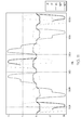
- Figure 3 is a graph of voltage waveforms when performing the simulation of Figure 2 ;
- Figure 4 is a graph showing the input voltage and current waveforms used in the simulation of Figure 2 ;
- Figure 5 is a graph showing a Fast-Fourier Transform (FFT) of the current input waveform (400 Hz fundamental) of Figure 4 ;
- FFT Fast-Fourier Transform
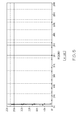
- Figure 6 is a graph showing the total input current and the current to the autotransformer during the simulation of Figure 2 ;
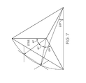
- Figure 7 is one leg of a construction diagram for an 18-pulse autotransformer according to an embodiment of the present invention.
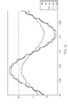
- Figure 8 is a graph showing phase current waveforms for comparison of 18-pulse composite autotransformer types
- Figure 9 is a graph showing currents to the main rectifiers for comparison of composite autotransformer types
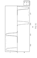
- Figure 10 is a graph showing current waveforms of all rectifier outputs for an 18-pulse composite autotransformer
- Figure 11 is a graph showing currents within windings of one autotransformer leg for an 18-pulse composite autotransformer.
- Figure 12 is a graph showing voltages within windings of one autotransformer leg for an 18-pulse composite autotransformer.
- embodiments of the present invention provide a 24-pulse composite AC-to-DC converter.
- composite AC-to-DC converter has been coined to distinguish a converter using two or more conversion methods in parallel.
- All the autotransformers used in these composite systems may satisfy a transformer vector diagram constructed using the vertices of an equilateral-triangle and an arc swung between them equal to the length of one of the triangle's legs.
- the number of autotransformer phase outputs may then be determined by the number of equally spaced rays drawn from the midpoint of the equilateral triangle. The intersection points of these rays with the arc may be used to design the autotransformer's windings voltage ratios and interconnections.
- An autotransformer designed this way may have output voltages of lower amplitude than the voltage source, while the voltage source amplitude alone may define the system's DC output level. Because of the voltage and phase differences, the load current may split into two paths. A large portion of the load current may be rectified directly through a main rectifier bridge. The remainder of the load current may flow through the autotransformer and may be rectified by auxiliary bridge rectifiers.
- the composite AC-to-DC converter according to the present invention may reduce autotransformer size and weight and should greatly improve the rectification system efficiency.
- TDD total harmonic distortion
- the characteristic current harmonics of a six-pulse rectification system include the 5 th , 7 th , 11 th , 13 th , 17 th , 19 th , and 23 rd of the fundamental. These harmonics have considerable magnitude and for the six-pulse system can exceed 33 percent of the fundamental. Theory predicts that going to higher pulse rectifier systems will reduce a system's current THD. For example, a 12-pulse rectifier may have about 8.5 percent current THD (no harmonic below the 11 th ), an 18-pulse rectifier may have about 3 percent current THD (no harmonic below the 17 th ), and a 24-pulse rectifier may have about 1.5 percent current THD (no harmonic below the 23 rd ) .
- Autotransformer conversion ratio (ACR) is used as means to compare different autotransformers. Equation 2 has been used as a basis of comparison of autotransformer size and weight.
- ACR 2 * IDC out * VDC out / ⁇ Vrms * Irms where Vrms are the voltages at each individual winding in volt -rms values; Irms are the currents in each individual winding in amps-rms values; VDC out is the output rectified voltage in volts; and IDC out is the output rectified current in amps.
- the unit of the ACR is W/VA.
- a typical autotransformer used in various conventional converter designs has an ACR of 1.53 W/VA. This is the autotransformer presently used in the A350 VCRUMC and CDMMC controller designs.
- the estimated ACR for the smallest 18-pulse autotransformer from U.S. Patent Number 6,396,723 is 3.53 W/VA.
- the estimated equivalent ACR for the 24-pulse autotransformer according to an embodiment of the present invention is 3.64 W/VA.
- the 24-pulse autotransformer from this estimate is potentially only 0.38 the size and weight of the autotransformer presently used in several conventional designs.
- the expected size and weight saving from AC to DC conversion is at least two times.
- FIG. 1 there is shown one leg of a construction diagram 10 for the 24-pulse autotransformer according to an embodiment of the present invention.
- the midpoint autotransformers used in the composite systems of the present invention satisfy a transformer diagram constructed using the vertices of an equilateral-triangle and an arc swung between them equal to the length of one of the triangle's legs.
- the number of autotransformer phase outputs may then be determined by the number of equally spaced rays drawn from the midpoint of the equilateral triangle. The intersection points of these rays with the arc may be used to design the autotransformer's windings voltage ratios and interconnections.
- An autotransformer designed this way may have output voltages of lower amplitude than the voltage source, while the voltage source amplitude alone fixes the DC output level of the system. Because of the voltage and phase differences, the load current splits into two paths. A large portion of the load current is rectified directly through a main rectifier bridge. The remainder of the load current flows through the autotransformer and is rectified by auxiliary bridge rectifiers. This composite AC-to-DC converter concept reduces autotransformer size and weight and greatly improves the system efficiency. Many other vector combinations exist that may achieve the coordinates of intersection of the three rays and arc needed for a 24-pulse configuration.
- FIG. 2 A simulation of this 24-pulse AC-to-DC converter for a 400Hz system representing this configuration is shown in Figure 2 , supplying a 9 kW resistive load.
- the windings associated with each of the three-phase autotransformer legs are grouped within dashed-line rectangles 20a, 20b, 20c.
- the output from each of the autotransformer legs 20a, 20b, 20c may pass through auxiliary rectifiers 22a, 22b, 22c.
- an input AC waveform 26 may be split with a substantial portion of load current being rectified through a main 6-diode rectifier bridge 24 and the remaining portion of load current flowing through an autotransformer 20 to be rectified by the auxiliary bridge rectifiers 22a, 22b, 22c.
- the voltages to the four three-phase rectifiers show the system output characteristic with reduced voltage amplitudes at the transformer (V(D34:2), V(D32:1) and V(D36:2)), when compared to the source input (V(D28:2), V(D29:2) and V(D30:2)).
- This voltage and phase characteristics may cause the source current to split between a main rectifier and the auxiliary rectifiers supplied by the autotransformer.
- the source voltages and currents may show nearly unity power factor. Like all rectifier systems, the power factor will depend on additional input filters and system loading, as shown in Figure 4 .
- Figure 5 is a Fast-Fourier Transform (FFT) of the current waveform (400 Hz fundamental). Very small harmonics of the input current can be seen in Figure 5 .
- FFT Fast-Fourier Transform
- the input phase current that is directed to the auto transformer may be a fraction of the total current.
- An input phase current is the sum of two currents, one going to the transformer and the other to the main rectifier.
- the significance of this aspect of the present invention is that the autotransformer may have less loss than one that carries all the input phase current.
- the RMS current into the autotransformer may be about 50 percent of the phase current total.
- Rectifier current contributions to a 9 kW resistive load demonstrate the current division between main and auxiliary rectifiers within the composite AC/DC converter. Because the auxiliary rectifiers may experience lower RMS current, with respect to the main rectifier, they may be smaller devices than those used for the main rectifier.
- Patent 6,396,723 These "midpoint" autotransformer benefits can be illustrated with simulations that show an increased amount of current bypassed to the main rectifier along with the reduction of the 5 th harmonic current component in the phase waveforms.
- the 5 th harmonic is the lowest frequency present in these current waveforms and, as such, if required to be further reduced, will need a larger filter.
- FIG. 7 One leg of the construction diagram for the proposed midpoint 18-pulse autotransformer is shown in Figure 7 . Many other vector combinations exist that may achieve the coordinates of intersection of the two rays and arc needed for this 18-pulse configuration.
- This midpoint autotransformer construction may determine winding turn ratios that differ from the U.S. Patent 6,396,723 autotransformer of similar topology by as much as 20 percent.
- More input current may be bypassed around the midpoint-constructed autotransformer compared to a vertex-constructed one.
- a midpoint 18-pulse-type composite autotransformer system bypasses an additional 0.55 to 0.67 percent of the RMS input current directly to the main rectifier, as shown in Figure 9 . This is due to the differences in the constructor ray angles used for the midpoint autotransformer design. The benefit of bypassing more current around the autotransformer is that it gives a slight increase in system AC/DC conversion efficiency.
- Rectifier current contributions to a 9-kW resistive load demonstrate the current division between main and auxiliary rectifiers within the composite AC/DC converter. Because the auxiliary rectifiers experience lower RMS current, with respect to the main rectifier, they may be smaller devices than those used for the main rectifier (see Figure 10 ).
Landscapes
- Engineering & Computer Science (AREA)
- Power Engineering (AREA)
- Rectifiers (AREA)
Applications Claiming Priority (1)
| Application Number | Priority Date | Filing Date | Title |
|---|---|---|---|
| US13/271,785 US8755207B2 (en) | 2011-10-12 | 2011-10-12 | Composite AC-to-DC power converter using midpoint method |
Publications (3)
| Publication Number | Publication Date |
|---|---|
| EP2582027A2 true EP2582027A2 (de) | 2013-04-17 |
| EP2582027A3 EP2582027A3 (de) | 2017-05-31 |
| EP2582027B1 EP2582027B1 (de) | 2018-09-05 |
Family
ID=47010320
Family Applications (1)
| Application Number | Title | Priority Date | Filing Date |
|---|---|---|---|
| EP12187137.0A Active EP2582027B1 (de) | 2011-10-12 | 2012-10-03 | Zusammengesetzter wechselstrom-gleichstrom-wandler mit mittelpunktverfahren |
Country Status (3)
| Country | Link |
|---|---|
| US (1) | US8755207B2 (de) |
| EP (1) | EP2582027B1 (de) |
| CN (1) | CN103051212B (de) |
Cited By (2)
| Publication number | Priority date | Publication date | Assignee | Title |
|---|---|---|---|---|
| RU184790U1 (ru) * | 2018-06-13 | 2018-11-09 | федеральное государственное бюджетное образовательное учреждение высшего образования "Уфимский государственный авиационный технический университет" | Многопульсное выпрямительное устройство |
| WO2021011052A1 (en) | 2019-07-16 | 2021-01-21 | Eldec Corporation | Asymmetric 24-pulse autotransformer rectifier unit for turboelectric propulsion, and associated systems and methods |
Families Citing this family (8)
| Publication number | Priority date | Publication date | Assignee | Title |
|---|---|---|---|---|
| US9331596B2 (en) * | 2013-05-15 | 2016-05-03 | Honeywell International Inc. | Composite AC-to-DC power converter with boosting capabilities using T configuration |
| US9058929B2 (en) * | 2013-07-10 | 2015-06-16 | Honeywell International Inc. | Composite AC-to-DC power converter with boosting capabilities |
| CN103368411A (zh) * | 2013-07-24 | 2013-10-23 | 山东新风光电子科技发展有限公司 | 一种多相变频电源 |
| CN104980047A (zh) * | 2015-06-15 | 2015-10-14 | 南京航空航天大学 | 基于星型原边绕组移相的24脉冲航空自耦变压整流器 |
| US10318904B2 (en) | 2016-05-06 | 2019-06-11 | General Electric Company | Computing system to control the use of physical state attainment of assets to meet temporal performance criteria |
| US10950382B1 (en) * | 2020-01-10 | 2021-03-16 | The Boeing Company | Autotransformer rectifier unit with multiple alternating current level outputs |
| FR3129377B1 (fr) * | 2021-11-25 | 2023-11-24 | Safran | Fourniture d’energie dans un aeronef utilisant un contrôle de statisme |
| CN114759808A (zh) * | 2022-04-29 | 2022-07-15 | 中国电子科技集团公司第十四研究所 | 一种dp型不对称式24脉自耦变压整流器 |
Citations (1)
| Publication number | Priority date | Publication date | Assignee | Title |
|---|---|---|---|---|
| US6396723B2 (en) | 2000-06-15 | 2002-05-28 | Kabushiki Kaisha Toshiba | Rectifier and transformer thereof |
Family Cites Families (9)
| Publication number | Priority date | Publication date | Assignee | Title |
|---|---|---|---|---|
| US5124904A (en) * | 1990-08-17 | 1992-06-23 | Westinghouse Electric Corp. | Optimized 18-pulse type AC/DC, or DC/AC, converter system |
| US6498736B1 (en) * | 2001-03-27 | 2002-12-24 | Baldor Electric Company | Harmonic filter with low cost magnetics |
| US6388430B1 (en) | 2001-09-13 | 2002-05-14 | The Esab Group, Inc. | Buck regulator circuit for use in a power supply |
| US6950322B2 (en) | 2003-04-10 | 2005-09-27 | Rsm Electron Power, Inc. | Regulated AC to DC converter for aerospace applications |
| US6995993B2 (en) | 2003-10-14 | 2006-02-07 | Honeywell International, Inc. | Rectification system for improving power quality of electrical power systems |
| FR2875971B1 (fr) | 2004-09-24 | 2006-11-10 | Thales Sa | Convertisseur alternatif-continu pour l'aeronautique |
| EP2111686A4 (de) * | 2007-01-22 | 2015-09-23 | Eldec Corp | Wechselstrom-gleichstrom-wandler für raumfahrtanwendungen |
| US8315071B2 (en) * | 2009-11-03 | 2012-11-20 | Honeywell International Inc. | Composite 24-pulse AC to DC power converter having a main rectifier and multiple auxiliary rectifiers |
| CN102013817A (zh) * | 2010-10-30 | 2011-04-13 | 江苏华鹏变压器有限公司 | 三相48脉波整流变压器 |
-
2011
- 2011-10-12 US US13/271,785 patent/US8755207B2/en active Active
-
2012
- 2012-10-03 EP EP12187137.0A patent/EP2582027B1/de active Active
- 2012-10-11 CN CN201210478562.8A patent/CN103051212B/zh active Active
Patent Citations (1)
| Publication number | Priority date | Publication date | Assignee | Title |
|---|---|---|---|---|
| US6396723B2 (en) | 2000-06-15 | 2002-05-28 | Kabushiki Kaisha Toshiba | Rectifier and transformer thereof |
Cited By (4)
| Publication number | Priority date | Publication date | Assignee | Title |
|---|---|---|---|---|
| RU184790U1 (ru) * | 2018-06-13 | 2018-11-09 | федеральное государственное бюджетное образовательное учреждение высшего образования "Уфимский государственный авиационный технический университет" | Многопульсное выпрямительное устройство |
| WO2021011052A1 (en) | 2019-07-16 | 2021-01-21 | Eldec Corporation | Asymmetric 24-pulse autotransformer rectifier unit for turboelectric propulsion, and associated systems and methods |
| EP4000081A4 (de) * | 2019-07-16 | 2023-11-08 | Eldec Corporation | Asymmetrische 24-puls-autotransformator-gleichrichtereinheit für einen turboelektrischen antrieb und zugehörige systeme und verfahren |
| AU2020315516B2 (en) * | 2019-07-16 | 2025-08-28 | Eldec Corporation | Asymmetric 24-pulse autotransformer rectifier unit for turboelectric propulsion, and associated systems and methods |
Also Published As
| Publication number | Publication date |
|---|---|
| CN103051212A (zh) | 2013-04-17 |
| EP2582027A3 (de) | 2017-05-31 |
| US8755207B2 (en) | 2014-06-17 |
| US20130094257A1 (en) | 2013-04-18 |
| CN103051212B (zh) | 2016-12-21 |
| EP2582027B1 (de) | 2018-09-05 |
Similar Documents
| Publication | Publication Date | Title |
|---|---|---|
| US8755207B2 (en) | Composite AC-to-DC power converter using midpoint method | |
| US8315071B2 (en) | Composite 24-pulse AC to DC power converter having a main rectifier and multiple auxiliary rectifiers | |
| US20130170257A1 (en) | Composite ac-to-dc power converter using wye architecture | |
| EP2595297A2 (de) | Integrierter AD/DC Leistungswandler mit Spartransformator und Hochstellfähigkeit | |
| Abdollahi et al. | A novel more electric aircraft power system rectifier based on a low-rating autotransformer | |
| Chen et al. | A novel parallel configured 48-pulse autotransformer rectifier for aviation application | |
| CN104300770A (zh) | 飞行器通用电力转换器 | |
| Abdollahi | Harmonic mitigation using 36-pulse AC-DC converter for direct torque controlled induction motor drives | |
| Abdollahi et al. | A parallel-connected 40-pulse diode rectifier with DC-link passive pulse multiplication circuit | |
| Eid et al. | Simulation and transient analysis of conventional and advanced aircraft electric power systems with harmonics mitigation | |
| Abdollahi | A simple harmonic reduction method in 20-pulse AC–DC converter | |
| Rehman et al. | Packed U‐Cell Inverter and Its Variants with Fault Tolerant Capabilities for More Electric Aircraft | |
| Bossi et al. | A battery-based auxiliary power system for an all-electric aircraft: A novel converter configuration | |
| Abdollahi et al. | Multi-pulse rectifier performance improvement using a high efficiency parallel combined harmonic suppression circuit for more electric aircraft power systems | |
| Krishnamoorthy et al. | Solid state auto-transformer concept for multi-pulse rectifiers | |
| Matheson et al. | Power quality specification development for more electric airplane architectures | |
| US9236811B2 (en) | Multiphase transformer rectifier unit | |
| Abdel-Fadil et al. | Fuzzy logic control of modern aircraft electrical power system during transient and steady-state operating conditions | |
| Eid et al. | Constant frequency aircraft electric power systems with harmonic reduction | |
| Vitoi et al. | Analysis of 12-pulse diode rectifier operating in aircraft systems with constant frequency | |
| Mastromauro et al. | An advanced active rectifier based on the single-star bridge cells modular multilevel cascade converter for more-electric-aircrafts applications | |
| Malek et al. | A novel 36-pulse star rectifier with passive injection circuits at DC link | |
| Abdollahi | A 12-pulse rectifier with passive harmonic reduction based on UIPT in more electric aircrafts | |
| Abdollahi | A novel tapped delta autotransformer based 72-pulse AC-DC converter with reduced kilovolt-ampere rating for power quality improvement | |
| Setlak et al. | Study of multi-pulse rectifiers of the PES system in accordance with the concept of a more electric aircraft |
Legal Events
| Date | Code | Title | Description |
|---|---|---|---|
| PUAI | Public reference made under article 153(3) epc to a published international application that has entered the european phase |
Free format text: ORIGINAL CODE: 0009012 |
|
| 17P | Request for examination filed |
Effective date: 20121003 |
|
| AK | Designated contracting states |
Kind code of ref document: A2 Designated state(s): AL AT BE BG CH CY CZ DE DK EE ES FI FR GB GR HR HU IE IS IT LI LT LU LV MC MK MT NL NO PL PT RO RS SE SI SK SM TR |
|
| AX | Request for extension of the european patent |
Extension state: BA ME |
|
| RAP1 | Party data changed (applicant data changed or rights of an application transferred) |
Owner name: HONEYWELL INTERNATIONAL INC. |
|
| PUAL | Search report despatched |
Free format text: ORIGINAL CODE: 0009013 |
|
| AK | Designated contracting states |
Kind code of ref document: A3 Designated state(s): AL AT BE BG CH CY CZ DE DK EE ES FI FR GB GR HR HU IE IS IT LI LT LU LV MC MK MT NL NO PL PT RO RS SE SI SK SM TR |
|
| AX | Request for extension of the european patent |
Extension state: BA ME |
|
| RIC1 | Information provided on ipc code assigned before grant |
Ipc: H02M 7/08 20060101ALI20170426BHEP Ipc: H02M 1/12 20060101AFI20170426BHEP |
|
| 17Q | First examination report despatched |
Effective date: 20170518 |
|
| GRAP | Despatch of communication of intention to grant a patent |
Free format text: ORIGINAL CODE: EPIDOSNIGR1 |
|
| INTG | Intention to grant announced |
Effective date: 20180420 |
|
| GRAS | Grant fee paid |
Free format text: ORIGINAL CODE: EPIDOSNIGR3 |
|
| GRAA | (expected) grant |
Free format text: ORIGINAL CODE: 0009210 |
|
| AK | Designated contracting states |
Kind code of ref document: B1 Designated state(s): AL AT BE BG CH CY CZ DE DK EE ES FI FR GB GR HR HU IE IS IT LI LT LU LV MC MK MT NL NO PL PT RO RS SE SI SK SM TR |
|
| REG | Reference to a national code |
Ref country code: GB Ref legal event code: FG4D |
|
| REG | Reference to a national code |
Ref country code: CH Ref legal event code: EP |
|
| REG | Reference to a national code |
Ref country code: AT Ref legal event code: REF Ref document number: 1038998 Country of ref document: AT Kind code of ref document: T Effective date: 20180915 |
|
| REG | Reference to a national code |
Ref country code: IE Ref legal event code: FG4D |
|
| REG | Reference to a national code |
Ref country code: DE Ref legal event code: R096 Ref document number: 602012050595 Country of ref document: DE |
|
| REG | Reference to a national code |
Ref country code: FR Ref legal event code: PLFP Year of fee payment: 7 |
|
| REG | Reference to a national code |
Ref country code: NL Ref legal event code: MP Effective date: 20180905 |
|
| REG | Reference to a national code |
Ref country code: LT Ref legal event code: MG4D |
|
| PG25 | Lapsed in a contracting state [announced via postgrant information from national office to epo] |
Ref country code: NO Free format text: LAPSE BECAUSE OF FAILURE TO SUBMIT A TRANSLATION OF THE DESCRIPTION OR TO PAY THE FEE WITHIN THE PRESCRIBED TIME-LIMIT Effective date: 20181205 Ref country code: BG Free format text: LAPSE BECAUSE OF FAILURE TO SUBMIT A TRANSLATION OF THE DESCRIPTION OR TO PAY THE FEE WITHIN THE PRESCRIBED TIME-LIMIT Effective date: 20181205 Ref country code: RS Free format text: LAPSE BECAUSE OF FAILURE TO SUBMIT A TRANSLATION OF THE DESCRIPTION OR TO PAY THE FEE WITHIN THE PRESCRIBED TIME-LIMIT Effective date: 20180905 Ref country code: LT Free format text: LAPSE BECAUSE OF FAILURE TO SUBMIT A TRANSLATION OF THE DESCRIPTION OR TO PAY THE FEE WITHIN THE PRESCRIBED TIME-LIMIT Effective date: 20180905 Ref country code: SE Free format text: LAPSE BECAUSE OF FAILURE TO SUBMIT A TRANSLATION OF THE DESCRIPTION OR TO PAY THE FEE WITHIN THE PRESCRIBED TIME-LIMIT Effective date: 20180905 Ref country code: GR Free format text: LAPSE BECAUSE OF FAILURE TO SUBMIT A TRANSLATION OF THE DESCRIPTION OR TO PAY THE FEE WITHIN THE PRESCRIBED TIME-LIMIT Effective date: 20181206 Ref country code: FI Free format text: LAPSE BECAUSE OF FAILURE TO SUBMIT A TRANSLATION OF THE DESCRIPTION OR TO PAY THE FEE WITHIN THE PRESCRIBED TIME-LIMIT Effective date: 20180905 |
|
| REG | Reference to a national code |
Ref country code: AT Ref legal event code: MK05 Ref document number: 1038998 Country of ref document: AT Kind code of ref document: T Effective date: 20180905 |
|
| PG25 | Lapsed in a contracting state [announced via postgrant information from national office to epo] |
Ref country code: AL Free format text: LAPSE BECAUSE OF FAILURE TO SUBMIT A TRANSLATION OF THE DESCRIPTION OR TO PAY THE FEE WITHIN THE PRESCRIBED TIME-LIMIT Effective date: 20180905 Ref country code: LV Free format text: LAPSE BECAUSE OF FAILURE TO SUBMIT A TRANSLATION OF THE DESCRIPTION OR TO PAY THE FEE WITHIN THE PRESCRIBED TIME-LIMIT Effective date: 20180905 Ref country code: HR Free format text: LAPSE BECAUSE OF FAILURE TO SUBMIT A TRANSLATION OF THE DESCRIPTION OR TO PAY THE FEE WITHIN THE PRESCRIBED TIME-LIMIT Effective date: 20180905 |
|
| PG25 | Lapsed in a contracting state [announced via postgrant information from national office to epo] |
Ref country code: NL Free format text: LAPSE BECAUSE OF FAILURE TO SUBMIT A TRANSLATION OF THE DESCRIPTION OR TO PAY THE FEE WITHIN THE PRESCRIBED TIME-LIMIT Effective date: 20180905 Ref country code: IS Free format text: LAPSE BECAUSE OF FAILURE TO SUBMIT A TRANSLATION OF THE DESCRIPTION OR TO PAY THE FEE WITHIN THE PRESCRIBED TIME-LIMIT Effective date: 20190105 Ref country code: PL Free format text: LAPSE BECAUSE OF FAILURE TO SUBMIT A TRANSLATION OF THE DESCRIPTION OR TO PAY THE FEE WITHIN THE PRESCRIBED TIME-LIMIT Effective date: 20180905 Ref country code: EE Free format text: LAPSE BECAUSE OF FAILURE TO SUBMIT A TRANSLATION OF THE DESCRIPTION OR TO PAY THE FEE WITHIN THE PRESCRIBED TIME-LIMIT Effective date: 20180905 Ref country code: AT Free format text: LAPSE BECAUSE OF FAILURE TO SUBMIT A TRANSLATION OF THE DESCRIPTION OR TO PAY THE FEE WITHIN THE PRESCRIBED TIME-LIMIT Effective date: 20180905 Ref country code: CZ Free format text: LAPSE BECAUSE OF FAILURE TO SUBMIT A TRANSLATION OF THE DESCRIPTION OR TO PAY THE FEE WITHIN THE PRESCRIBED TIME-LIMIT Effective date: 20180905 Ref country code: IT Free format text: LAPSE BECAUSE OF FAILURE TO SUBMIT A TRANSLATION OF THE DESCRIPTION OR TO PAY THE FEE WITHIN THE PRESCRIBED TIME-LIMIT Effective date: 20180905 Ref country code: ES Free format text: LAPSE BECAUSE OF FAILURE TO SUBMIT A TRANSLATION OF THE DESCRIPTION OR TO PAY THE FEE WITHIN THE PRESCRIBED TIME-LIMIT Effective date: 20180905 Ref country code: RO Free format text: LAPSE BECAUSE OF FAILURE TO SUBMIT A TRANSLATION OF THE DESCRIPTION OR TO PAY THE FEE WITHIN THE PRESCRIBED TIME-LIMIT Effective date: 20180905 |
|
| PG25 | Lapsed in a contracting state [announced via postgrant information from national office to epo] |
Ref country code: SM Free format text: LAPSE BECAUSE OF FAILURE TO SUBMIT A TRANSLATION OF THE DESCRIPTION OR TO PAY THE FEE WITHIN THE PRESCRIBED TIME-LIMIT Effective date: 20180905 Ref country code: PT Free format text: LAPSE BECAUSE OF FAILURE TO SUBMIT A TRANSLATION OF THE DESCRIPTION OR TO PAY THE FEE WITHIN THE PRESCRIBED TIME-LIMIT Effective date: 20190105 Ref country code: SK Free format text: LAPSE BECAUSE OF FAILURE TO SUBMIT A TRANSLATION OF THE DESCRIPTION OR TO PAY THE FEE WITHIN THE PRESCRIBED TIME-LIMIT Effective date: 20180905 |
|
| REG | Reference to a national code |
Ref country code: CH Ref legal event code: PL |
|
| REG | Reference to a national code |
Ref country code: DE Ref legal event code: R097 Ref document number: 602012050595 Country of ref document: DE |
|
| REG | Reference to a national code |
Ref country code: BE Ref legal event code: MM Effective date: 20181031 |
|
| PG25 | Lapsed in a contracting state [announced via postgrant information from national office to epo] |
Ref country code: LU Free format text: LAPSE BECAUSE OF NON-PAYMENT OF DUE FEES Effective date: 20181003 |
|
| PLBE | No opposition filed within time limit |
Free format text: ORIGINAL CODE: 0009261 |
|
| STAA | Information on the status of an ep patent application or granted ep patent |
Free format text: STATUS: NO OPPOSITION FILED WITHIN TIME LIMIT |
|
| REG | Reference to a national code |
Ref country code: IE Ref legal event code: MM4A |
|
| PG25 | Lapsed in a contracting state [announced via postgrant information from national office to epo] |
Ref country code: DK Free format text: LAPSE BECAUSE OF FAILURE TO SUBMIT A TRANSLATION OF THE DESCRIPTION OR TO PAY THE FEE WITHIN THE PRESCRIBED TIME-LIMIT Effective date: 20180905 Ref country code: MC Free format text: LAPSE BECAUSE OF FAILURE TO SUBMIT A TRANSLATION OF THE DESCRIPTION OR TO PAY THE FEE WITHIN THE PRESCRIBED TIME-LIMIT Effective date: 20180905 |
|
| 26N | No opposition filed |
Effective date: 20190606 |
|
| PG25 | Lapsed in a contracting state [announced via postgrant information from national office to epo] |
Ref country code: BE Free format text: LAPSE BECAUSE OF NON-PAYMENT OF DUE FEES Effective date: 20181031 Ref country code: LI Free format text: LAPSE BECAUSE OF NON-PAYMENT OF DUE FEES Effective date: 20181031 Ref country code: CH Free format text: LAPSE BECAUSE OF NON-PAYMENT OF DUE FEES Effective date: 20181031 Ref country code: SI Free format text: LAPSE BECAUSE OF FAILURE TO SUBMIT A TRANSLATION OF THE DESCRIPTION OR TO PAY THE FEE WITHIN THE PRESCRIBED TIME-LIMIT Effective date: 20180905 |
|
| PG25 | Lapsed in a contracting state [announced via postgrant information from national office to epo] |
Ref country code: IE Free format text: LAPSE BECAUSE OF NON-PAYMENT OF DUE FEES Effective date: 20181003 |
|
| PG25 | Lapsed in a contracting state [announced via postgrant information from national office to epo] |
Ref country code: MT Free format text: LAPSE BECAUSE OF NON-PAYMENT OF DUE FEES Effective date: 20181003 |
|
| PG25 | Lapsed in a contracting state [announced via postgrant information from national office to epo] |
Ref country code: TR Free format text: LAPSE BECAUSE OF FAILURE TO SUBMIT A TRANSLATION OF THE DESCRIPTION OR TO PAY THE FEE WITHIN THE PRESCRIBED TIME-LIMIT Effective date: 20180905 |
|
| PG25 | Lapsed in a contracting state [announced via postgrant information from national office to epo] |
Ref country code: CY Free format text: LAPSE BECAUSE OF FAILURE TO SUBMIT A TRANSLATION OF THE DESCRIPTION OR TO PAY THE FEE WITHIN THE PRESCRIBED TIME-LIMIT Effective date: 20180905 Ref country code: HU Free format text: LAPSE BECAUSE OF FAILURE TO SUBMIT A TRANSLATION OF THE DESCRIPTION OR TO PAY THE FEE WITHIN THE PRESCRIBED TIME-LIMIT; INVALID AB INITIO Effective date: 20121003 Ref country code: MK Free format text: LAPSE BECAUSE OF NON-PAYMENT OF DUE FEES Effective date: 20180905 |
|
| P01 | Opt-out of the competence of the unified patent court (upc) registered |
Effective date: 20230525 |
|
| PGFP | Annual fee paid to national office [announced via postgrant information from national office to epo] |
Ref country code: FR Payment date: 20241025 Year of fee payment: 13 |
|
| PGFP | Annual fee paid to national office [announced via postgrant information from national office to epo] |
Ref country code: DE Payment date: 20251028 Year of fee payment: 14 |
|
| PGFP | Annual fee paid to national office [announced via postgrant information from national office to epo] |
Ref country code: GB Payment date: 20251023 Year of fee payment: 14 |