EP2582193A1 - Procédé et dispositif pour la transmission de signaux de référence - Google Patents
Procédé et dispositif pour la transmission de signaux de référence Download PDFInfo
- Publication number
- EP2582193A1 EP2582193A1 EP11791913.4A EP11791913A EP2582193A1 EP 2582193 A1 EP2582193 A1 EP 2582193A1 EP 11791913 A EP11791913 A EP 11791913A EP 2582193 A1 EP2582193 A1 EP 2582193A1
- Authority
- EP
- European Patent Office
- Prior art keywords
- transmission
- antennas
- mapping relationship
- resources
- transmission layer
- Prior art date
- Legal status (The legal status is an assumption and is not a legal conclusion. Google has not performed a legal analysis and makes no representation as to the accuracy of the status listed.)
- Withdrawn
Links
Images


Classifications
-
- H—ELECTRICITY
- H04—ELECTRIC COMMUNICATION TECHNIQUE
- H04B—TRANSMISSION
- H04B7/00—Radio transmission systems, i.e. using radiation field
- H04B7/02—Diversity systems; Multi-antenna system, i.e. transmission or reception using multiple antennas
- H04B7/04—Diversity systems; Multi-antenna system, i.e. transmission or reception using multiple antennas using two or more spaced independent antennas
- H04B7/06—Diversity systems; Multi-antenna system, i.e. transmission or reception using multiple antennas using two or more spaced independent antennas at the transmitting station
- H04B7/0613—Diversity systems; Multi-antenna system, i.e. transmission or reception using multiple antennas using two or more spaced independent antennas at the transmitting station using simultaneous transmission
- H04B7/0684—Diversity systems; Multi-antenna system, i.e. transmission or reception using multiple antennas using two or more spaced independent antennas at the transmitting station using simultaneous transmission using different training sequences per antenna
-
- H—ELECTRICITY
- H04—ELECTRIC COMMUNICATION TECHNIQUE
- H04W—WIRELESS COMMUNICATION NETWORKS
- H04W72/00—Local resource management
- H04W72/50—Allocation or scheduling criteria for wireless resources
- H04W72/54—Allocation or scheduling criteria for wireless resources based on quality criteria
- H04W72/541—Allocation or scheduling criteria for wireless resources based on quality criteria using the level of interference
-
- H—ELECTRICITY
- H04—ELECTRIC COMMUNICATION TECHNIQUE
- H04L—TRANSMISSION OF DIGITAL INFORMATION, e.g. TELEGRAPHIC COMMUNICATION
- H04L27/00—Modulated-carrier systems
- H04L27/26—Systems using multi-frequency codes
- H04L27/2601—Multicarrier modulation systems
- H04L27/2602—Signal structure
- H04L27/261—Details of reference signals
- H04L27/2613—Structure of the reference signals
-
- H—ELECTRICITY
- H04—ELECTRIC COMMUNICATION TECHNIQUE
- H04L—TRANSMISSION OF DIGITAL INFORMATION, e.g. TELEGRAPHIC COMMUNICATION
- H04L5/00—Arrangements affording multiple use of the transmission path
- H04L5/0001—Arrangements for dividing the transmission path
- H04L5/0014—Three-dimensional division
- H04L5/0023—Time-frequency-space
-
- H—ELECTRICITY
- H04—ELECTRIC COMMUNICATION TECHNIQUE
- H04L—TRANSMISSION OF DIGITAL INFORMATION, e.g. TELEGRAPHIC COMMUNICATION
- H04L5/00—Arrangements affording multiple use of the transmission path
- H04L5/003—Arrangements for allocating sub-channels of the transmission path
- H04L5/0048—Allocation of pilot signals, i.e. of signals known to the receiver
Definitions
- the present invention relates to the field of wireless communication technology, and particularly to a method and a device for transmitting a reference signal.
- a Base Station transmits a signaling to a User Equipment (UE) to control the UE to transmit a reference signal (RS) to the BS
- UE User Equipment
- RS reference signal
- the BS can transmit the signaling to the UE to control the UE to transmit N RSs from M antennas simultaneously, wherein the RS corresponding to each transmission layer is generated from its corresponding RS resource, and transmitted via an antenna corresponding to the transmission layer.
- LTE-Advanced Long Term Evolution-Advanced
- the BS can control the UE through the signaling to map the RSs corresponding to a plurality of transmission layers to a plurality of antennas for a transmission.
- the transmitted different RSs undergo different interferences from an RS transmitted by other UE.
- the performance for the BS to detect the RSs transmitted from those antennas is very likely to be quite poor.
- the embodiments of the present invention provide a method and a device for transmitting a reference signal (RS), so as to improve the anti-interference abilities of the RS transmitted via the antennas.
- RS reference signal
- the present invention provides a method for transmitting an RS, wherein the method is applicable to a scenario where a UE has at least two antennas which correspond to at least two transmission layers and at least two RS resources, wherein a mapping relationship exists between the antennas, the transmission layers and the RS resources, each transmission layer corresponds to one RS resource and each transmission layer corresponds to at least one antenna, the method comprising:
- the present invention provides a communication device, wherein the communication device has at least two antennas which correspond to at least two transmission layers and at least two RS resources, wherein a mapping relationship exists between the antennas, the transmission layers and the RS resources, each transmission layer corresponds to one RS resource and each transmission layer corresponds to at least one antenna, the communication device comprising:
- the present invention provides a method for transmitting an RS, wherein the method is applicable to a scenario where a UE has at least two antennas which correspond to at least two transmission layers and at least two RS resources, wherein a mapping relationship exists between the antennas, the transmission layers and the RS resources, each transmission layer corresponds to one RS resource and each transmission layer corresponds to at least one antenna, wherein at a first RS transmission time, an RS transmitted via an antenna corresponding to each transmission layer is generated by the UE on the transmission layer by using an RS resource corresponding to the transmission layer based on the mapping relationship; the method comprising:
- the present invention provides a base station, wherein the base station is applicable to a scenario where a UE has at least two antennas which correspond to at least two transmission layers and at least two RS resources, wherein a mapping relationship exists between the antennas, the transmission layers and the RS resources, each transmission layer corresponds to one RS resource and each transmission layer corresponds to at least one antenna, wherein at a first RS transmission time, an RS transmitted via an antenna corresponding to each transmission layer is generated by the UE on the transmission layer by using an RS resource corresponding to the transmission layer based on the mapping relationship; the base station comprising:
- the UE has at least two antennas, and there are at least two transmission layers and at least two RS resources, wherein each transmission layer corresponds to one RS resource and each transmission layer corresponds to at least one antenna.
- the UE generates an RS on each transmission layer by using an RS resource corresponding to the transmission layer based on a mapping relationship existing between the antennas, the transmission layers and the RS resources, and transmits the generated RS via an antenna corresponding to the transmission layer;
- the UE changes the mapping relationship between the antennas, the transmission layers and the RS resources.
- the UE generates an RS on each transmission layer by using an RS resource corresponding to the transmission layer based on the changed mapping relationship, and transmits the generated RS via an antenna corresponding to the transmission layer.
- the present invention avoids the problem that the performance for the BS to detect the RSs transmitted from those antennas is very likely to be quite poor because the RS transmitted via those antennas continuously undergo strong interferences from other UEs, and improves the anti-interference abilities of the RS transmitted via the antennas.
- the UE has at least two antennas, which correspond to at least two transmission layers and at least two RS resources, wherein a mapping relationship exists between the antennas, the transmission layers and the RS resources; each transmission layer corresponds to one RS resource and each transmission layer corresponds to at least one antenna.
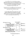
- Fig. 1 provides a method for transmitting an RS, including the steps of:
- a layer mapping module maps a first transmission layer to antennas 1, 2, and maps a second transmission layer to antennas 3, 4, respectively; an RS generating module corresponding to the first transmission layer generates, on the first transmission layer, an RS of the first transmission layer by using RS resource 1, and the UE transmits the RS of the first transmission layer via antennas 1, 2 corresponding to the first transmission layer; and an RS generating module corresponding to the second transmission layer generates, on the second transmission layer, an RS of the second transmission layer by using RS resource 2, and the UE transmits the RS of the second transmission layer via antennas 3, 4 corresponding to the second transmission layer.
- the UE changes the mapping relationship between the antennas, the transmission layers and the RS resources.
- the UE changes RS resource 1 corresponding to the first transmission layer into RS resource 2, and changes RS resource 2 corresponding to the second transmission layer into RS resource 1, respectively.
- the schematic diagram of the changed UE side is illustrated in Fig. 3 .
- the UE at a second RS transmission time, based on the changed mapping relationship, the UE generates an RS on each transmission layer by using an RS resource corresponding to the transmission layer, and transmits the generated RS via an antenna corresponding to the transmission layer.
- the RS generating module corresponding to the first transmission layer generates, on the first transmission layer, an RS of the first transmission layer by using RS resource 2, and the UE transmits the RS of the first transmission layer via antennas 1, 2 corresponding to the first transmission layer; and the RS generating module corresponding to the second transmission layer generates, on the second transmission layer, an RS of the second transmission layer by using RS resource 1, and the UE transmits the RS of the second transmission layer via antennas 3, 4 corresponding to the second transmission layer.
- the first RS transmission time and the second RS transmission time are only used to distinguish the two RS transmission time, rather than defining the specific positional relationship between the two RS transmission time.
- the first RS transmission time and the second RS transmission time may be two RS transmission time neighboring or not neighboring to each other.
- the first RS transmission time and second RS transmission time also do not limit the number of the RS transmission time in the embodiment of the present invention.
- the UE described in the embodiment of the present invention can change the RS transmitted via the antennas at different transmission time, thereby avoiding the problem that the performance for the BS to detect the RS transmitted from those antennas is very likely to be quite poor when the RS transmitted via certain antennas continuously undergo strong interferences from the RS transmitted by other UEs, and improving the anti-interference abilities of the RS transmitted via the antennas.
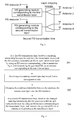
- the embodiment as illustrated in Fig. 4 provides a method for transmitting an RS, including the steps of:
- a layer mapping module maps a first transmission layer to antennas 1, 2, and maps a second transmission layer to antennas 3, 4, respectively; an RS generating module corresponding to the first transmission layer generates, on the first transmission layer, an RS of the first transmission layer by using RS resource 1, and the UE transmits the RS of the first transmission layer via antennas 1, 2 corresponding to the first transmission layer; and an RS generating module corresponding to the second transmission layer generates, on the second transmission layer, an RS of the second transmission layer by using RS resource 2, and the UE transmits the RS of the second transmission layer via antennas 3, 4 corresponding to the second transmission layer.
- the UE receives a remapping control signaling sent from a correspondent node, wherein the signaling may be transmitted independently or carried in another signaling.
- the signaling may be carried in a signaling employed by the BS to notify the UE to transmit data in the layer shifting mode, a signaling employed by the BS to notify the UE to always transmit the RS of each layer in one-to-one correspondence with the data stream of that layer, a signaling employed by the BS to notify the UE to transmit one codeword from a plurality of antennas simultaneously, a signaling employed by the BS to notify the UE to transmit more than one codeword from a plurality of antennas simultaneously, a signaling employed by the BS to notify the UE to receive an ACK/NAK of a plurality of codewords in a binding mode, a signaling employed by the BS to notify the UE to receive a plurality of ACKs/NAKs of a plurality of codewords, a signaling employed by the BS to notify the UE to be served jointly by a plurality of cells, or a signaling employed by the BS to notify the UE of the RS resources used in
- the UE changes the mapping relationship between the antennas, the transmission layers and the RS resources based on the remapping control signaling.
- antennas 1, 2 may be set as a first antenna group
- antennas 3, 4 may be set as a second antenna group.
- the UE changes antennas 1, 2 in the first antenna group corresponding to the first transmission layer into antennas 3, 4 in the second antenna group corresponding to the second transmission layer, and changes antennas 3, 4 in the second antenna group corresponding to the second transmission layer into antennas 1, 2 in the first antenna group corresponding to the first transmission layer, respectively.
- the schematic diagram of the UE side after the change of the mapping relationship is illustrated in Fig. 5 .
- one antenna in the first antenna group may also be exchanged with one antenna in the second antenna group.
- antenna 1 in the first antenna group is changed into antenna 3 in the second antenna group while antenna 2 remains unchanged; and antenna 3 in the second antenna group is changed into antenna 1 in the first antenna group while antenna 4 remains unchanged.
- the UE based on the changed mapping relationship, the UE generates an RS on each transmission layer by using an RS resource corresponding to the transmission layer, and transmits the generated RS via an antenna corresponding to the transmission layer at the second RS transmission time.
- the RS generating module corresponding to the first transmission layer generates, on the first transmission layer, an RS of the first transmission layer by using RS resource 1, and the UE transmits the RS of the first transmission layer via antennas 3, 4 corresponding to the first transmission layer;
- the RS generating module corresponding to the second transmission layer generates, on the second transmission layer, an RS of the second transmission layer by using RS resource 2, and the UE transmits the RS of the second transmission layer via antennas 1, 2 corresponding to the second transmission layer.
- mapping relationship between two transmission time An operation of changing the mapping relationship between two transmission time is described in the above application scenario.
- such an operation of changing the mapping relationship may be performed continuously at different transmission time.
- the mapping relationship is changed again between the second and third transmission time, and the same transmission mode used at the first transmission time may be employed at the third transmission time.
- the mapping relationship is changed again between the third and fourth transmission time, and the same transmission mode used at the second transmission time may be employed at the fourth transmission time.
- the RS transmitted via the antennas are also changed, and the strong interference on one antenna can be dispersed to other antennas, thereby avoiding the problem in the prior art that the performance for the BS to detect the RS transmitted from those antennas is very likely to be quite poor, and improving the anti-interference abilities of the RS transmitted via the antennas.
- the UE when the UE transmits the data in the layer shifting mode (i.e., the UE exchanges a plurality of layers of data on different data symbols), it automatically changes the RS resources used by different transmission layers at different time.
- the UE always transmits the RS of each layer in one-to-one correspondence with the data stream of that layer for example, when two layers of data streams are to be transmitted by the UE, the UE always transmits the RS corresponding to the first transmission layer in one-to-one correspondence with the data stream of the first transmission layer on a same antenna, and always transmits the RS corresponding to the second transmission layer in one-to-one correspondence with the data stream of the second transmission layer on a same antenna, thereby changing the RS resources used by different transmission layers at different time automatically.
- the UE when the UE transmits one codeword from a plurality of antennas simultaneously, it automatically changes the RS resources used by different transmission layers or different antennas at different time, wherein one codeword denotes one independent packet. Or, when the UE transmits more than one codeword from a plurality of antennas simultaneously, it changes the RS resources used by different transmission layers at different time automatically. Or, when the UE receives an ACK/NAK of a plurality of codewords in a binding mode (i.e., the UE only receives one ACK/NAK to acquire whether the transmitted codewords have been correctly demodulated by the BS), it automatically changes the RS resources used by different transmission layers at different time.
- the UE when the UE receives a plurality of ACKs/NAKs of a plurality of codewords (i.e., the UE receives a plurality of ACKs/NAKs to acquire whether the transmitted codewords have been correctly demodulated by the BS, respectively), it automatically changes the RS resources used by different transmission layers at different time. Or, when the UE is served by a plurality of cells jointly, it automatically changes the RS resources used by different transmission layers at different time.
- the process may specifically include: when the UE detects that the signal of a neighbor cell is stronger than a certain threshold, it is deemed that the UE is served by a plurality of cells jointly, and then the UE automatically changes the RS resources used by different transmission layers at different time.
- the RS resources used by the UE when the RS resources used by the UE have a low orthogonality, the RS resources used by different transmission layers are automatically changed at different time. For example, when the UE uses #0 cyclic shift CS0 and #3 cyclic shift CS3 to transmit the RS corresponding to two transmission layers, it changes the RS resources used by different transmission layers at different time since CS0 and CS3 have a low orthogonality.
- the criterion for judging whether or not "the RS resources used by the UE have a low orthogonality" may be preset on both of the sides of the UE and the BS, thus the BS does not need to transmit a signaling to the UE for notification.
- the BS may also notify the UE of the criterion, for example as follows: when the distance between the CSs used by the UE in different layers is less than 4, it is determined that "the RS resources used by the UE have a low orthogonality". Thus, if the UE uses CS0 and CS4, no change needs to be made; while if the UE uses CS0 and CS3, it automatically changes the RS resources used by different transmission layers at different time.
- the different RS transmission time is transmission time corresponding to a different DM RS in the same transmission time interval.
- one TTI includes 2 timeslots each having one DM RS symbol, then the operation of changing the mapping relationship occurs at the DM RS transmission time in two timeslots in the same TTI.
- the different RS transmission time is transmission time corresponding to a different SRS.
- the time when the UE transmits SRS is the last symbol of one TTI, and the UE periodically transmits the SRS; assuming that the period is two TTIs, then the operation of changing the mapping relationship occurs between the last symbols of every two TTIs.
- the RS resource may be a Cyclic Shift (CS) used by the RS.
- CS Cyclic Shift
- a plurality of RSs transmitted by the UE are obtained by performing different cyclic shiftings to the same sequence. If the UE transmits RSs of two layers, the UE performs, at the first RS transmission time, cyclic shiftings to the sequence in correspondence with the first and second transmission layers using parameters CS1 and CS2, respectively, to generate RSs of two layers, and the UE performs, at the second RS transmission time, cyclic shiftings in correspondence with the first and second transmission layers using parameters CS2 and CS1, respectively, to generate RSs of two layers.
- the RS resource may be a comb used by the RS.
- different RSs may use different combs.
- comb 1 indicates to transmit RSs on the 1st, 3rd, 5th, 7th, ..., (2N-1)-th subcarriers (N is a positive integer and the number of the available subcarriers is 2N), and comb 2 indicates to transmit RSs on the 2nd, 4th, 6th, 8th, ..., 2N-th subcarriers.
- the UE when the UE transmits RSs of two layers, the UE generates, at the first RS transmission time, RSs of two layers in correspondence with the first and second transmission layers using combs 1 and 2, respectively, and generates, at the second RS transmission time, RSs of two layers in correspondence with the first and second transmission layers using combs 2 and 1, respectively.
- Solution 1 the UE changes a mapping relationship between transmission layers corresponding to a same codeword and RS resources corresponding to the transmission layers corresponding to the same codeword.
- a first codeword corresponds to a first and a second transmission layers, with the first transmission layer corresponding to RS resource 1 and the second transmission layer corresponding to RS resource 2; and a second codeword corresponds to a third and a fourth transmission layers, with the third transmission layer corresponding to RS resource 3 and a fourth transmission layer corresponding to RS resource 4.
- an RS generating module corresponding to the first transmission layer generates an RS corresponding to the first transmission layer by using RS resource 1
- an RS generating module corresponding to the second transmission layer generates an RS corresponding to the second transmission layer by using RS resource 2
- the mapping relationship is changed, at the second RS transmission time, the RS generating module corresponding to the first transmission layer generates the RS corresponding to the first transmission layer by using RS resource 2
- the RS generating module corresponding to the second transmission layer generates the RS corresponding to the second transmission layer by using RS resource 1.
- an RS generating module corresponding to the third transmission layer generates an RS corresponding to the third transmission layer by using RS resource 3
- an RS generating module corresponding to the fourth transmission layer generates an RS corresponding to the fourth transmission layer by using RS resource 4
- the RS generating module corresponding to the third transmission layer generates the RS corresponding to the third transmission layer by using RS resource 4
- the RS generating module corresponding to the fourth transmission layer generates the RS corresponding to the fourth transmission layer by using RS resource 3.
- Solution 2 the UE changes a mapping relationship between transmission layers corresponding to different codewords and RS resources corresponding to the transmission layers corresponding to the different codewords.
- the UE side as illustrated in Fig. 6 is taken as an example.
- a first codeword corresponds to a first and a second transmission layers, with the first transmission layer corresponding to RS resource 1 and the second transmission layer corresponding to RS resource 2;
- a second codeword corresponds to a third and a fourth transmission layers, with the third transmission layer corresponding to RS resource 3 and the fourth transmission layer corresponding to RS resource 4.
- the UE At the first RS transmission time, the UE generates an RS corresponding to the first transmission layer by using RS resource 1, and generates an RS corresponding to the second transmission layer by using RS resource 2, respectively; after the mapping relationship is changed, at the second RS transmission time, the UE generates the RS corresponding to the first transmission layer by using RS resource 3, and generates the RS corresponding to the second transmission layer by using RS resource 4, respectively.
- the UE generates an RS corresponding to the third transmission layer by using RS resource 3, and generates an RS corresponding to the fourth transmission layer by using RS resource 4, respectively; after the mapping relationship is changed, at the second RS transmission time, the UE generates the RS corresponding to the third transmission layer by using RS resource 1, and generates the RS corresponding to the fourth transmission layer by using RS resource 2, respectively.
- Solutions 1 and 2 can be implemented in a combination, i.e., exchanging corresponding RS resources between different RS layers corresponding to the same codeword and between different RS layers corresponding to different codewords.
- the processing at the first transmission time is introduced by taking the UE side as illustrated in Fig. 6 as an example, and the scenario of the second transmission time is illustrated in Fig. 9 , assuming that the UE transmits four RSs in four transmission layers, wherein a first codeword corresponds to a first and a second transmission layers, with the first transmission layer corresponding to RS resource 1 and the second transmission layer corresponding to RS resource 2; and a second codeword corresponds to a third and a fourth transmission layers, with the third transmission layer corresponding to RS resource 3 and the fourth transmission layer corresponding to RS resource 4.
- the UE At the first RS transmission time, the UE generates an RS corresponding to the first transmission layer by using RS resource 1, and generates an RS corresponding to the second transmission layer by using RS resource 2, respectively; after the mapping relationship is changed, at the second RS transmission time, the UE generates the RS corresponding to the first transmission layer by using RS resource 4, and generates the RS corresponding to the second transmission layer by using RS resource 3, respectively.
- the UE generates an RS corresponding to the third transmission layer by using RS resource 3, and generates an RS corresponding to the fourth transmission layer by using RS resource 4, respectively; after the mapping relationship is changed, at the second RS transmission time, the UE generates the RS corresponding to the third transmission layer by using RS resource 2, and generates the RS corresponding to the fourth transmission layer by using RS resource 1, respectively.
- Solution 3 the UE changes a mapping relationship between transmission layers corresponding to a same codeword and antennas corresponding to the transmission layers corresponding to the same codeword.
- Solution 3 is similar to solution 1, and the distinction lies in that solution 1 changes the mapping relationship between the transmission layers corresponding to the same codeword and the RS resources corresponding to the transmission layers, while solution 3 changes the mapping relationship between the transmission layers corresponding to the same codeword and the antennas corresponding to the transmission layers.
- the process of changing the mapping relationship is the same and hereby the detailed description is omitted herein.
- Solution 4 the UE changes a mapping relationship between transmission layers corresponding to different codewords and antennas corresponding to the transmission layers corresponding to the different codewords.
- Solution 4 is similar to solution 2, and the distinction lies in that solution 2 changes the mapping relationship between the transmission layers corresponding to different codewords and the RS resources corresponding to the transmission layers, while solution 4 changes the mapping relationship between the transmission layers corresponding to different codewords and the antennas corresponding to the transmission layers.
- the process of changing the mapping relationship is the same and hereby the detailed description is omitted herein.
- Solution 5 the UE sequentially performs cyclic shiftings to RS resources respectively corresponding to different transmission layers using a first cyclic digit in a set cyclic direction.
- the BS allocates four RS resources to the UE, i.e., RS resource 1, RS resource 2, RS resource 3 and RS resource 4 as illustrated in Fig. 10
- the UE generates, on a first DM RS symbol, RSs corresponding to the first to fourth transmission layers using RS resource 1, RS resource 2, RS resource 3 and RS resource 4, respectively.
- the UE generates, on a second DM RS symbol, RSs corresponding to the first to fourth transmission layers using RS resource 3, RS resource 4, RS resource 1 and RS resource 2, respectively.
- the RS resource is the CS
- the BS allocates to the UE four CSs, i.e., CS0, CS3, CS6 and CS9, respectively
- the UE generates, on the first DM RS symbol, RSs corresponding to the first to fourth transmission layers using CS0, CS3, CS6 and CS9, respectively, and generates, on the second DM RS symbol, RSs corresponding to the first to fourth transmission layers using CS6, CS9, CS0 and CS3, respectively.
- the UE when the SRSs are to be transmitted, if the BS allocates four RS resources to the UE, i.e., RS resource 1, RS resource 2, RS resource 3 and RS resource 4, respectively, the UE generates, on a first SRS period, RSs corresponding to the first to fourth transmission layers using RS resource 1, RS resource 2, RS resource 3 and RS resource 4, respectively; the UE generates, on a second SRS period, RSs corresponding to the first to fourth transmission layers using RS resource 2, RS resource 3, RS resource 4 and RS resource 1, respectively; the UE generates, on a third SRS period, RSs corresponding to the first to fourth transmission layers using RS resource 3, RS resource 4, RS resource 1 and RS resource 2, respectively; and the UE generates, on a fourth SRS period, RSs corresponding to the first to fourth transmission layers using RS resource 4, RS resource 1, RS resource 2 and RS resource 3, respectively. That is, the UE performs cyclic shiftings to the
- the cyclic direction may be sequential or inversely sequential. For example, in the sequential direction, if at the first RS transmission time, the RSs corresponding to the first to fourth transmission layers are generated from RS resource 1, RS resource 2, RS resource 3 and RS resource 4, then at the second RS transmission time, the RSs corresponding to the first to fourth transmission layers are generated from RS resource 2, RS resource 3, RS resource 4 and RS resource 1.
- the RSs corresponding to the first to fourth transmission layers are generated from RS resource 1, RS resource 2, RS resource 3 and RS resource 4, then at the second RS transmission time, the RSs corresponding to the first to fourth transmission layers are generated from RS resource 4, RS resource 1, RS resource 2 and RS resource 3.
- the cyclic direction and the first cyclic digit may be preset on both of the sides of the BS and the UE, so that the BS does not need to transmit any signaling to the UE, and the signaling can be saved.
- the cyclic direction and the first cyclic digit may also be configured by the BS.
- the BS transmits a signaling to the UE to configure the cyclic direction and the first cyclic digit; after receiving the signaling, the UE sequentially performs cyclic shiftings to the RS resources corresponding to the different transmission layers based on the signaling.
- the BS allocates four RS resources to the UE, i.e., RS resource 1, RS resource 2, RS resource 3 and RS resource 4, respectively, and notifies the UE that the cyclic direction is sequential and the first cyclic digit is 1, the UE generates, on a first DM RS symbol, RSs corresponding to the first to fourth transmission layers by using RS resource 1, RS resource 2, RS resource 3 and RS resource 4, respectively; and the UE generates, on a second DM RS symbol, RSs corresponding to the first to fourth transmission layers by using RS resource 2, RS resource 3, RS resource 4 and RS resource 1, respectively.
- RS resource 1 RS resource 2
- RS resource 3 and RS resource 4 respectively
- the first cyclic digit in the cyclic mode may also be generated from any one or any combination of the following parameters: a current cell ID, a subframe index, the number of the RS layers, the number of the antenna groups, and index information indicating the RS resources.
- the cyclic digit when the cyclic digit is generated from the current cell ID, it may be represented as [ ID cell mod( N layer -1)]+1 , wherein ID cell indicates the cell ID, N layer indicates the number of the RS layers, and mod indicates a modular operation.
- the cyclic digit when the cyclic digit is generated from the subframe index, it may be represented as [ Index subframe mod( N layer -1)] + 1, wherein Index subframe indicates the subframe index.
- the cyclic digit when the cyclic digit is generated from the index of the RS layers, the cyclic digit may be represented as N layer -1. Alternatively, the cyclic digit may also be generated from the number of the antenna groups.
- the UE may determine that the RS resources allocated by the BS to the UE include CS0 and CS6; and if the BS transmits information to the UE to notify the UE that the CS used by one of the RSs is CS3, the UE may determine that the RS resources allocated by the BS to the UE include CS3 and CS9.
- the cyclic digit may be represented as I RS mod 2, wherein I RS indicates information of RS resources transmitted by the BS to the UE, and it may be a CS number used by one of the RSs of the UE.
- I RS indicates information of RS resources transmitted by the BS to the UE, and it may be a CS number used by one of the RSs of the UE.
- the solution can also sequentially perform cyclic shiftings to the antennas corresponding to the different transmission layers.
- the implementation is the similar and hereby the detailed description is omitted herein.
- Solution 6 the UE changes the mapping relationship between the antennas, the transmission layers and the RS resources according to the set remapping scheme.
- the BS allocates to the UE three RS resources, i.e., RS resource 1, RS resource 2 and RS resource 3, respectively, the UE generates, on a first DM RS symbol, RSs corresponding to the first to third transmission layers using RS resources 1 to 3, respectively.
- resources used by the UE to generate RSs corresponding to the first to third transmission layers may be one of the schemes shown in the following table.
- the first RS transmission time RS resources corresponding to the first to third transmission layers
- the second RS transmission time RS resources corresponding to the first to third transmission layers Scheme 1 RS resource 1, RS resource 2, RS resource 3 RS resource 1, RS resource 3, RS resource 2 Scheme 2 RS resource 1, RS resource 2, RS resource 3 RS resource 2, RS resource 1, RS resource 3 Scheme 3 RS resource 1, RS resource 2, RS resource 3 RS resource 2, RS resource 3, RS resource 1 Scheme 4 RS resource 1, RS resource 2, RS resource 3 RS resource 3, RS resource 1, RS resource 2 Scheme 5 RS resource 1, RS resource 2, RS resource 3 RS resource 3, RS resource 2, RS resource 1
- the table and which scheme to be used may be preset on the sides of the UE and the BS, or notified to the UE by the BS through a signaling so as to be more flexible. For example, when the BS transmits a signaling to notify the UE to use scheme 2, the UE generates, on the second DM RS symbol, RSs corresponding to the first to third transmission layers using RS resource 2, RS resource 1 and RS resource3, respectively.
- the index of one selected from at least two candidate exchange schemes in the above table may also be generated from any of the following parameters: the current cell ID, a subframe index, the number of the RS layers, the number of the antenna groups, and index information indicating the RS resources.
- the specific generation process is the same as the generation process of the cyclic digit in the cyclic mode used in Solution 5, and hereby the detailed description is omitted herein.
- the same or different technical solutions for changing the mapping relationship may be used to transmit the DM RSs and the SRSs.
- the current UE may be indicated to transmit the DM RSs and the SRSs by using the same or different technical solutions for changing the mapping relationship.
- the BS may also notify the configuration by transmitting a signaling to the UE, so as to control the UE to transmit the DM RSs and the SRSs by using the same or different technical solutions for changing the mapping relationship.
- the BS only needs to transmit one signaling to the UE, and after receiving the signaling sent by the BS, the UE can exchange the used RS resources in the same method for the DM RSs and the SRSs at different RS transmission time, thereby saving the signaling.
- the BS may transmit a plurality of signaling to the UE to control schemes for changing the mapping relationship used for the DM RSs and the SRSs, respectively, and after receiving the signaling sent by the BS, the UE exchanges the used RS resources for the DM RSs and the SRSs at different RS transmission time, respectively, based on the plurality of signaling, thereby achieving a higher flexibility.
- the signaling may be notified to the UE semi-statically, i.e., the UE performs relevant operation always using the previously received instruction before receiving a new instruction.
- the signaling may be notified to the UE dynamically, i.e., before the UE transmits an RS each time, the BS needs to transmit an instruction to the UE to control the UE to perform relevant operation.
- the BS may notify the signaling to a single UE through unicast, to a plurality of UEs through multi-cast, or to all UEs in the cell through broadcast.
- the BS may transfer the signaling to the UE in a Physical Downlink Control Channel (PDCCH), a Physical Downlink Shared Channel (PDSCH) or a Broadcasting Channel (BCH).
- PDCCH Physical Downlink Control Channel
- PDSCH Physical Downlink Shared Channel
- BCH Broadcasting Channel
- the present invention may be implemented through hardware or a combination of software and necessary common hardware platform. Based on such a understanding, the technical solution of the present invention may be reflected in a form of software product storable in a nonvolatile storage medium (e.g., CD-ROM, USB flash disk, mobile hard disk, etc.), including several instructions to enable a computer device (e.g., personal computer, server, network equipment, etc.) to execute the methods described in the embodiments of the present invention.
- a nonvolatile storage medium e.g., CD-ROM, USB flash disk, mobile hard disk, etc.
- the embodiment as illustrated in Fig. 12 provides a communication device for implementing the above method, including a first processing unit 11 and a remapping unit 12.
- the first processing unit 11 is configured to generate an RS on each transmission layer by using an RS resource corresponding to the transmission layer based on the mapping relationship, and transmit the generated RS via an antenna corresponding to the transmission layer at a first RS transmission time.
- the remapping unit 12 is configured to change the mapping relationship between the antennas, the transmission layers and the RS resources.
- the first processing unit 11 is further configured to generate an RS on each transmission layer by using an RS resource corresponding to the transmission layer based on the changed mapping relationship, and transmit the generated RS via the antenna corresponding to the transmission layer at a second RS transmission time.
- the communication device described in the embodiment of the present invention can change the RS transmitted via the antennas at different transmission time, thereby avoiding the problem that the performance for the BS to detect the RS transmitted from those antennas is very likely to be quite poor when the RS transmitted via certain antennas continuously undergo strong interferences from the RS transmitted by other UE, and improving the anti-interference abilities of the RS transmitted via the antennas.
- the communication device further includes a receiving unit 13.
- the receiving unit 13 is configured to receive a remapping control signaling sent from a correspondent node before the remapping unit 12 changes the mapping relationship between the antennas, the transmission layers and the RS resources.
- the signaling may be transmitted independently or carried in another signaling.
- the remapping unit changes the mapping relationship between the antennas, the transmission layers and the RS resources based on the remapping control signaling.
- the remapping unit includes at least one of a first modifying module and a second modifying module.
- the first modifying module is configured to change a mapping relationship between transmission layers corresponding to a same codeword and RS resources corresponding to the transmission layers corresponding to the same codeword.
- the first modifying module is further configured to change a mapping relationship between transmission layers corresponding to different codewords and RS resources corresponding to the transmission layers corresponding to the different codewords.
- the second modifying module is configured to change a mapping relationship between transmission layers corresponding to a same codeword and antennas corresponding to the transmission layers corresponding to the same codeword.
- the second modifying module is further configured to change a mapping relationship between transmission layers corresponding to different codewords and antennas corresponding to the transmission layers corresponding to the different codewords.
- the remapping unit includes at least one of a third modifying module and a fourth modifying module.
- the third modifying module is configured to sequentially perform cyclic shiftings to RS resources respectively corresponding to different transmission layers using a first cyclic digit in a set cyclic direction.
- the third modifying module is further configured to sequentially perform cyclic shiftings to antennas respectively corresponding to different transmission layers using the first cyclic digit in the set cyclic direction.
- the first cyclic digit in the cyclic mode may also be generated from any one or any combination of the following parameters: a current cell ID, a subframe index, the number of the RS layers, the number of the antenna groups, and index information indicating the RS resources.
- the cyclic direction and the first cyclic digit may be preset on both of the sides of the BS and the UE, so that the BS does not need to transmit any signaling to the UE, and the signaling can be saved.
- the fourth modifying module is configured to change the mapping relationship between the antennas, the transmission layers and the RS resources according to the set remapping scheme.
- the fourth modifying module selects one from at least two set remapping schemes according to any one or any combination of a current cell ID, a subframe index, the number of the RS layers, the number of the antenna groups, and index information of the RS resources, and changes the mapping relationship between the antennas, the transmission layers and the RS resources according to the selected remapping scheme, wherein the set remapping schemes may be preset in the communication device or sent by the correspondent node to the communication device.
- the correspondent node may be a BS.
- the embodiment of the present invention is mainly applied to the process of transmitting a plurality of RSs via a plurality of antennas, so as to improve the anti-interference abilities of the RSs transmitted via the antennas.
Landscapes
- Engineering & Computer Science (AREA)
- Signal Processing (AREA)
- Computer Networks & Wireless Communication (AREA)
- Quality & Reliability (AREA)
- Mobile Radio Communication Systems (AREA)
- Radio Transmission System (AREA)
Applications Claiming Priority (2)
| Application Number | Priority Date | Filing Date | Title |
|---|---|---|---|
| CN2010101968064A CN102281086A (zh) | 2010-06-10 | 2010-06-10 | 参考信号的传输方法及装置 |
| PCT/CN2011/075250 WO2011153922A1 (fr) | 2010-06-10 | 2011-06-03 | Procédé et dispositif pour la transmission de signaux de référence |
Publications (2)
| Publication Number | Publication Date |
|---|---|
| EP2582193A1 true EP2582193A1 (fr) | 2013-04-17 |
| EP2582193A4 EP2582193A4 (fr) | 2013-12-18 |
Family
ID=45097532
Family Applications (1)
| Application Number | Title | Priority Date | Filing Date |
|---|---|---|---|
| EP11791913.4A Withdrawn EP2582193A4 (fr) | 2010-06-10 | 2011-06-03 | Procédé et dispositif pour la transmission de signaux de référence |
Country Status (4)
| Country | Link |
|---|---|
| US (1) | US20130100935A1 (fr) |
| EP (1) | EP2582193A4 (fr) |
| CN (1) | CN102281086A (fr) |
| WO (1) | WO2011153922A1 (fr) |
Cited By (1)
| Publication number | Priority date | Publication date | Assignee | Title |
|---|---|---|---|---|
| WO2014193070A1 (fr) * | 2013-05-30 | 2014-12-04 | Lg Electronics Inc. | Extension de signaux de référence pour système mimo de masse |
Families Citing this family (8)
| Publication number | Priority date | Publication date | Assignee | Title |
|---|---|---|---|---|
| WO2008082277A2 (fr) | 2007-01-05 | 2008-07-10 | Lg Electronics Inc. | Méthodes de mappage de couches et de transmission de données pour système mimo |
| CN103944685B (zh) * | 2013-01-18 | 2017-10-10 | 华为技术有限公司 | 扩展参考信号的方法、设备和通信系统 |
| EP3148095B1 (fr) | 2014-06-17 | 2020-06-24 | Huawei Technologies Co. Ltd. | Procédé et appareil de transmission de données |
| KR20170098793A (ko) * | 2014-12-17 | 2017-08-30 | 소니 주식회사 | 장치 및 방법 |
| CN110199487B (zh) * | 2017-05-04 | 2021-01-29 | 华为技术有限公司 | 传输参考信号的方法和终端设备 |
| CN109151886B (zh) * | 2017-06-16 | 2021-04-20 | 华为技术有限公司 | 一种用于上报的方法、设备和系统 |
| US10554448B2 (en) * | 2017-08-10 | 2020-02-04 | Qualcomm Incorporated | Dynamic scheduling of data patterns for shortened transmission time intervals |
| CN115551102A (zh) * | 2021-06-29 | 2022-12-30 | 大唐移动通信设备有限公司 | 下行资源调度方法、网络设备、可读存储介质及程序产品 |
Family Cites Families (5)
| Publication number | Priority date | Publication date | Assignee | Title |
|---|---|---|---|---|
| EP3119050B1 (fr) * | 2007-08-17 | 2017-10-11 | Sun Patent Trust | Dispositif de communication radio et procédé de communication radio pour recevoir des signaux de référence |
| KR20090077657A (ko) * | 2008-01-11 | 2009-07-15 | 에스케이에너지 주식회사 | 배터리 관리 시스템에서 배터리의 soc 측정 방법 및 장치 |
| US8218663B2 (en) * | 2008-07-29 | 2012-07-10 | Texas Instruments Incorporated | Reference signal resource allocation for single user MIMO |
| CN101692620B (zh) * | 2009-09-04 | 2012-07-04 | 西安电子科技大学 | Lte-a中上行su-mimo的层交换方法 |
| CN101662443B (zh) * | 2009-09-18 | 2014-10-22 | 中兴通讯股份有限公司 | 一种参考信号的序列产生和映射方法及发送装置 |
-
2010
- 2010-06-10 CN CN2010101968064A patent/CN102281086A/zh active Pending
-
2011
- 2011-06-03 EP EP11791913.4A patent/EP2582193A4/fr not_active Withdrawn
- 2011-06-03 WO PCT/CN2011/075250 patent/WO2011153922A1/fr not_active Ceased
-
2012
- 2012-12-10 US US13/709,899 patent/US20130100935A1/en not_active Abandoned
Cited By (2)
| Publication number | Priority date | Publication date | Assignee | Title |
|---|---|---|---|---|
| WO2014193070A1 (fr) * | 2013-05-30 | 2014-12-04 | Lg Electronics Inc. | Extension de signaux de référence pour système mimo de masse |
| US9923613B2 (en) | 2013-05-30 | 2018-03-20 | Lg Electronics Inc. | Reference signals extension for massive MIMO system |
Also Published As
| Publication number | Publication date |
|---|---|
| CN102281086A (zh) | 2011-12-14 |
| EP2582193A4 (fr) | 2013-12-18 |
| US20130100935A1 (en) | 2013-04-25 |
| WO2011153922A1 (fr) | 2011-12-15 |
Similar Documents
| Publication | Publication Date | Title |
|---|---|---|
| US12069653B2 (en) | Method and apparatus for transmitting and receiving downlink control channel in communication system | |
| US12028868B2 (en) | Determination of physical downlink control channel (PDCCH) assignment in power saving mode | |
| CN111919411B (zh) | 支持ss/pbch块的大子载波间隔的方法和装置 | |
| US12238041B2 (en) | Methods and apparatuses for transmitting signal | |
| EP2582193A1 (fr) | Procédé et dispositif pour la transmission de signaux de référence | |
| JP7040615B2 (ja) | 端末、ネットワーク装置、及び方法 | |
| JP6220049B2 (ja) | 送信装置および制御信号配置方法 | |
| KR102033442B1 (ko) | 공통 검색 공간 및 ue 특정 검색 공간을 블라인드 검출하기 위한 방법 및 장치 | |
| EP2730041B1 (fr) | Système et procédé de signalisation et de transmission de signaux de référence de liaison montante | |
| EP3213454B1 (fr) | Attribution de ressources pour les répétitions des émissions dans un système de communication | |
| CN102355325B (zh) | 一种pucch资源映射的方法及装置 | |
| JP2025100693A (ja) | 無線通信システムにおいて物理上りリンク制御チャネルの送信方法、装置及びシステム | |
| US20140286297A1 (en) | Method and apparatus for transmitting downlink control information | |
| CN113966587A (zh) | 无线通信系统中的下行数据接收和harq-ack传输的方法、装置和系统 | |
| KR20200090835A (ko) | 독립형 nr 비면허 스펙트럼에 대한 초기 액세스 블록을 위한 방법 및 장치 | |
| CN104081851A (zh) | ePDCCH的搜索空间配置方法 | |
| CN102546134A (zh) | 基于增强phich传输反馈信息的方法及装置 | |
| CN102932932B (zh) | Srs与pusch的协调传输方法及系统 | |
| CN103249147B (zh) | 物理上行控制信道的资源配置方法和系统 | |
| US9236980B2 (en) | Control channel transmitting, receiving method, base station and terminal | |
| US12426061B2 (en) | Method for receiving physical control channel in wireless communication system, and device using same | |
| KR20150090047A (ko) | 무선 통신 시스템에서 하향링크 제어 신호를 수신 또는 전송하기 위한 방법 및 이를 위한 장치 | |
| CN111182641A (zh) | 一种被用于用户和基站中的方法和设备 | |
| JP7004012B2 (ja) | 端末デバイス、ネットワークデバイス、端末デバイスの方法、及びネットワークデバイスの方法 | |
| RU2589891C2 (ru) | Способ и устройство для отображения ресурсов физического канала управления нисходящей линии связи |
Legal Events
| Date | Code | Title | Description |
|---|---|---|---|
| PUAI | Public reference made under article 153(3) epc to a published international application that has entered the european phase |
Free format text: ORIGINAL CODE: 0009012 |
|
| 17P | Request for examination filed |
Effective date: 20121217 |
|
| AK | Designated contracting states |
Kind code of ref document: A1 Designated state(s): AL AT BE BG CH CY CZ DE DK EE ES FI FR GB GR HR HU IE IS IT LI LT LU LV MC MK MT NL NO PL PT RO RS SE SI SK SM TR |
|
| DAX | Request for extension of the european patent (deleted) | ||
| A4 | Supplementary search report drawn up and despatched |
Effective date: 20131115 |
|
| RIC1 | Information provided on ipc code assigned before grant |
Ipc: H04L 27/26 20060101ALI20131111BHEP Ipc: H04W 72/04 20090101AFI20131111BHEP |
|
| STAA | Information on the status of an ep patent application or granted ep patent |
Free format text: STATUS: THE APPLICATION HAS BEEN WITHDRAWN |
|
| 18W | Application withdrawn |
Effective date: 20140912 |