EP2582423B1 - Selbstreinigender shunt - Google Patents
Selbstreinigender shunt Download PDFInfo
- Publication number
- EP2582423B1 EP2582423B1 EP11795301.8A EP11795301A EP2582423B1 EP 2582423 B1 EP2582423 B1 EP 2582423B1 EP 11795301 A EP11795301 A EP 11795301A EP 2582423 B1 EP2582423 B1 EP 2582423B1
- Authority
- EP
- European Patent Office
- Prior art keywords
- tube
- shunt
- openings
- bristles
- fluid inlet
- Prior art date
- Legal status (The legal status is an assumption and is not a legal conclusion. Google has not performed a legal analysis and makes no representation as to the accuracy of the status listed.)
- Active
Links
- 238000004140 cleaning Methods 0.000 title claims description 56
- 239000012530 fluid Substances 0.000 claims description 31
- 230000005291 magnetic effect Effects 0.000 claims description 11
- 239000000696 magnetic material Substances 0.000 claims description 9
- 239000000463 material Substances 0.000 claims description 8
- 238000009434 installation Methods 0.000 claims description 6
- 238000002604 ultrasonography Methods 0.000 claims description 4
- 210000003128 head Anatomy 0.000 description 32
- 230000033001 locomotion Effects 0.000 description 15
- 238000000034 method Methods 0.000 description 13
- 210000001519 tissue Anatomy 0.000 description 13
- 210000001175 cerebrospinal fluid Anatomy 0.000 description 5
- 238000001356 surgical procedure Methods 0.000 description 5
- 230000005294 ferromagnetic effect Effects 0.000 description 4
- 208000015181 infectious disease Diseases 0.000 description 3
- 206010022840 Intraventricular haemorrhage Diseases 0.000 description 2
- 210000001015 abdomen Anatomy 0.000 description 2
- 210000000683 abdominal cavity Anatomy 0.000 description 2
- 230000000740 bleeding effect Effects 0.000 description 2
- 210000002987 choroid plexus Anatomy 0.000 description 2
- 230000006378 damage Effects 0.000 description 2
- 230000001419 dependent effect Effects 0.000 description 2
- 229920001296 polysiloxane Polymers 0.000 description 2
- 230000008467 tissue growth Effects 0.000 description 2
- 241000237858 Gastropoda Species 0.000 description 1
- 208000007536 Thrombosis Diseases 0.000 description 1
- 208000027418 Wounds and injury Diseases 0.000 description 1
- 230000001594 aberrant effect Effects 0.000 description 1
- 230000004913 activation Effects 0.000 description 1
- 238000003491 array Methods 0.000 description 1
- 230000000903 blocking effect Effects 0.000 description 1
- 239000008280 blood Substances 0.000 description 1
- 210000004369 blood Anatomy 0.000 description 1
- 230000002490 cerebral effect Effects 0.000 description 1
- 238000007428 craniotomy Methods 0.000 description 1
- 230000009193 crawling Effects 0.000 description 1
- 238000000502 dialysis Methods 0.000 description 1
- 239000003302 ferromagnetic material Substances 0.000 description 1
- 239000013305 flexible fiber Substances 0.000 description 1
- 238000011010 flushing procedure Methods 0.000 description 1
- 231100001261 hazardous Toxicity 0.000 description 1
- 208000003906 hydrocephalus Diseases 0.000 description 1
- 239000007943 implant Substances 0.000 description 1
- 208000014674 injury Diseases 0.000 description 1
- 238000003780 insertion Methods 0.000 description 1
- 230000037431 insertion Effects 0.000 description 1
- 238000007914 intraventricular administration Methods 0.000 description 1
- 230000005923 long-lasting effect Effects 0.000 description 1
- 230000007774 longterm Effects 0.000 description 1
- 238000010297 mechanical methods and process Methods 0.000 description 1
- 210000002418 meninge Anatomy 0.000 description 1
- 210000000056 organ Anatomy 0.000 description 1
- 230000000149 penetrating effect Effects 0.000 description 1
- 230000035515 penetration Effects 0.000 description 1
- 210000004303 peritoneum Anatomy 0.000 description 1
- 230000035945 sensitivity Effects 0.000 description 1
Images

Classifications
-
- A—HUMAN NECESSITIES
- A61—MEDICAL OR VETERINARY SCIENCE; HYGIENE
- A61M—DEVICES FOR INTRODUCING MEDIA INTO, OR ONTO, THE BODY; DEVICES FOR TRANSDUCING BODY MEDIA OR FOR TAKING MEDIA FROM THE BODY; DEVICES FOR PRODUCING OR ENDING SLEEP OR STUPOR
- A61M27/00—Drainage appliance for wounds or the like, i.e. wound drains, implanted drains
- A61M27/002—Implant devices for drainage of body fluids from one part of the body to another
- A61M27/006—Cerebrospinal drainage; Accessories therefor, e.g. valves
-
- B—PERFORMING OPERATIONS; TRANSPORTING
- B08—CLEANING
- B08B—CLEANING IN GENERAL; PREVENTION OF FOULING IN GENERAL
- B08B9/00—Cleaning hollow articles by methods or apparatus specially adapted thereto
- B08B9/02—Cleaning pipes or tubes or systems of pipes or tubes
- B08B9/027—Cleaning the internal surfaces; Removal of blockages
-
- A—HUMAN NECESSITIES
- A61—MEDICAL OR VETERINARY SCIENCE; HYGIENE
- A61M—DEVICES FOR INTRODUCING MEDIA INTO, OR ONTO, THE BODY; DEVICES FOR TRANSDUCING BODY MEDIA OR FOR TAKING MEDIA FROM THE BODY; DEVICES FOR PRODUCING OR ENDING SLEEP OR STUPOR
- A61M25/00—Catheters; Hollow probes
- A61M2025/0019—Cleaning catheters or the like, e.g. for reuse of the device, for avoiding replacement
Definitions
- the present invention relates to a self-cleaning inlet for a fluid shunt, especially for draining cerebrospinal fluid (CSF), as used in the treatment of hydrocephalus.
- CSF cerebrospinal fluid
- Fig. 1 illustrates a CSF shunt, implanted into the cranial cavity of a child.
- the shunt head 10 shown on a larger scale in Fig. 2 , consists of a hollow catheter 20, usually made of silicone, with a series of perforations 21, 22, along its length, the holes often having different sizes and different spacings, such that fluid accumulated round the shunt can drain through the holes into the tube, and away from the region from which the fluid has to be drained. The excess fluid is generally drained into a body cavity such as the abdomen.
- the shunt head may have length calibrations imprinted thereon, so that the physician can estimate how far it has been inserted into the cranial cavity.
- the shunt head is attached by means of a tubular connector 18 to a drain tube 12, which conveys the excess cerebral fluids typically into the patient's abdomen.
- the drain tube is generally implanted just beneath the skin, with access to the cranial region to be drained and into the abdominal cavity being achieved by means of small incisions 16 in the meninges and the peritoneum respectively.
- the end section of the drain tube 14 may be bundled up in the abdominal cavity, so that it can unravel as the child grows.
- CSF shunts are perhaps the most commonly used shunts, it is to be understood that such shunts could be applied to any other part of the body where the drainage of excess fluid is required, such as in urethral catheters, vesicostomy, peritoneal dialysis, and others. Furthermore, such shunts could also be used in industrial applications where it may be necessary to drain fluids from a remote inaccessible location.
- Figs 1 and 2 have a significant drawback in that after some period of time inside the human body, living tissue growth may result in blockage of the holes by the tissue. This tissue is generally the main cause of shunt blockage. When trying to withdraw the shunt by surgery, the ingrown tissue may tear, causing intraventricular bleeding, which might be life threatening.
- the present invention relates to a self cleaning shunt head as claimed hereafter. Preferred embodiments of the invention are set forth in the dependent claims. Associated methods are also described herein to aid understanding of the invention, but these do not form part of the claimed invention.
- the self cleaning shunt head comprises two components which operate co-operatively.
- the distal end of the shunt head is in the form of a tube having openings for draining the excess fluid, and this tube replaces the perforated end of the original shunt head.
- an internal elongate cleaning element which may conveniently be constructed of a central shaft with bristles protruding therefrom, which can penetrate the tube drain openings.
- the cleaning element resembles a long brush.
- the element or its bristles can be vibrated, such that the bristles generate a cleaning action inside the openings, cleaning out any debris or clotted blood found in them, and preventing living tissue from growing into them.
- the openings can be in the form of holes or slots, and are most advantageously arranged in a predetermined array.
- the positions of the bristles on the cleaning element should be arranged with a similar array pitch and angular positioning, such that the bristles are correctly positioned to enter the openings when cleaning element and tube are correctly aligned.
- the correct radial alignment may be achieved by any simple mechanical method, such as a keyway.
- the vibration can be effected by any method which enables remote vibration to be effected.
- a particularly simple method is to incorporate a ferromagnetic or even a magnetic element within the cleaning element, and to cause these to vibrate by means of an externally applied field magnetic field.
- the bristles could be manufactured of a ferromagnetic or magnetic material, such that they alone vibrate.
- Another alternative is use of an appropriate ultrasound field applied externally, causing the bristles to vibrate.
- a fluid inlet head for use on a shunt, the head comprising:
- the first tube may be essentially cylindrical.
- the bristles may be attached to a central shaft of the cleaning element.
- Additional implementations can include a fluid inlet head as described above, wherein the vibration generating system comprises an external field which operates on the cleaning element.
- the external field may be an alternating magnetic field
- the cleaning element then should comprise at least one of a magnetic material and a magnetized material.
- the shaft may be constructed of either one of a magnetic material and a magnetized material, and/or at least some of the bristles may be constructed of either one of a magnetic material and a magnetized material.
- the vibration generating system may comprise an externally applied ultrasonic field having a frequency in the range of the mechanical self-resonant frequency of at least some of the bristles.
- the vibration generating system in other exemplary implementation may be a vibration transducer disposed on the cleaning element, and could be any one of a mechanical, electromagnetic, or piezoelectric transducer, or another suitable type.
- any of the above-described heads may further have bristles of length such that they do not protrude substantially through the openings beyond the outer wall of the first tube.
- exemplary implementations of the fluid inlet head for use on a shunt may further comprise a second tube having a set of openings, at least some of which are disposed in the wall of the second tube in the same predetermined lateral and radial locations as those of the first tube, the second tube being installed inside the first tube, such that when the tubes are not aligned with their sets of openings mutually lined up, the bristles on the cleaning element cannot protrude into the openings in the first cylindrical tube.
- Such implementations should also comprise a mechanism for changing the alignment of the first and second tubes, such that the sets of openings can be mutually lined up only after installation of the fluid inlet head.
- Yet other implementations perform a method of maintaining clear the openings of a fluid inlet head for use on a shunt, comprising:
- the vibrating may be performed using an external field which operates on the cleaning element.
- the external field may be an alternating magnetic field, and the cleaning element should then comprise at least one of a magnetic material and a magnetized material.
- the shaft may be constructed of either one of a magnetic material and a magnetized material, or at least some of the bristles may be constructed of either one of a magnetic material and a magnetized material.
- the externally applied field may be an ultrasound field having a frequency in the range of the mechanical self-resonant frequency of at least some of the bristles.
- the cleaning element may further comprise a vibration transducer, and the vibration is performed by actuating the vibration transducer.
- a vibration transducer may be any one of a mechanical, electromagnetic, or piezoelectric transducer.
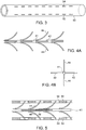
- Fig. 3 illustrates schematically an example of a tube element 50 suitable for use at the distal end of the shunt.
- the fluid draining openings are arranged in arrays of slots down the length of the tube, each array being positioned at a different angular position around the circumference of the tube.
- two visible rows of slots 52, 54 are shown arranged at angularly orthogonal positions relative to each other, but such a tube may typically have four such rows, arranged at 90° to each other, or any other number of rows of openings.
- the tube is shown having an essentially cylindrical profile, this being the most convenient shape to manufacturer, tubes with other sectional profile shapes can also be used in this application.
- Figs. 4A and 4B illustrate schematically a cleaning element adapted for use with the drain tube of Fig. 3.
- Fig. 4A is a side view of the cleaning element, while Fig. 4B is an end view thereof.
- the cleaner element has a central shaft 41 with a number of bristles 42, 44 attached thereto.
- the bristles are preferably located longitudinally along the shaft such that the distance between successive bristles is the same as the distance between successive openings in the tube. Likewise they should preferably be located radially around the shaft at the same angular intervals as the openings in the tube. In the example shown in Figs. 4A and 4B , four radial sets of bristles are shown located at right angles to each other. The arrangement of bristles should be such that when the cleaner is positioned correctly, the bristles are located opposite the openings in the tube.
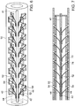
- Fig. 5 is a cutaway drawing of the head
- Fig. 6 is an "X-ray" isometric drawing of the head.
- the bristles 44 are shown protruding into the slots 54.
- both orthogonal sets of bristles are shown protruding into their respective slots. Bristles 44 extend in the vertical direction of the drawing upwards and downwards into the slots 54, while bristles 42 extended in the horizontal direction of the drawing sideways into the slots 52.
- the cleaning element In order for the bristles to perform their cleaning action, the cleaning element must be vibrated.
- One particularly simple way of achieving such vibration is by having one or more onboard magnets or ferromagnetic slugs attached to the cleaner shaft, or by making the cleaner shaft itself of a magnetic or magnetized material, and applying an external alternating magnetic field by means of a coil or a vibrating permanent magnet, that will influence the small magnet(s) or ferromagnetic element on the cleaner element and cause vibrations thereof.
- This implementation enables unlimited operation time, since the activation energy for generating the vibration is provided externally and is not dependent on the use of onboard batteries, while also maintaining simplicity of operation.
- the applied field direction may be such that the cleaning element vibrates along its length, or in any other direction other than axial which causes the bristles to penetrate the slot openings, or in any combination of such motions.
- the shaft diameter may be small compared with the internal diameter of the tube, sufficient clearance can be provided for the cleaner element to vibrate in a rotation motion around axes perpendicular to the axis of the tube, such that the cleaner performs a see-saw type of motion, with bristles at opposite ends penetrating slots at opposite sides of the tube.
- the vibratory motion generation system should be such as to reduce as much as possible sensitivity to direction of the externally applied field, so as not to restrict the positioning of the patient when the cleaning procedure is activated. Entry of bristles into the slots in any manner which results in successful clearance of the slots may be advantageous.
- the shaft it is possible to generate the vibrations directly in the bristles , such as by making them of a magnetized or a magnetic material and applying an external alternating magnetic field, or by any other suitable method.
- the external field can be applied from outside of the subject's body in which the shunt is installed.
- An alternative method of generating the vibrations could be by use of an ultrasound signal applied externally at a frequency related to the mechanical self-resonant frequency of the bristles, such that they vibrate when the field is applied.
- the vibrations must be of such magnitude and direction that the bristles vibrate within the openings in the tube.
- the bristles should penetrate the slots to their full depth, so that no tissue growth or blockage can occur at any depth in the slots. Limiting the extension outside the tube may be advisable in order to avoid injury to tissues around the tube, though some penetration outside the tube may be allowable. There may be several slots in different directions so that the cleaning process can be made less sensitive to the direction of the applied external field.
- the on-board vibration generator 56 mounted on the cleaning element, such as is shown schematically in Fig. 5 . Operation of the cleaning process can then be simpler, as there is no need to activate any external influence, but rather the cleaning is done autonomously.
- the on-board power supply may be long-lasting, or may be capable of being charged by an external power supply.
- the on-board vibration generator can be a mechanical transducer, such as by means of an eccentric or stepped rotating element, a magnetic transducer or a piezoelectric transducer, or any other form of vibration generator.
- the internal battery can be recharged when necessary by means of an externally applied induced field, as is known in the art.
- the vibration transducer can be provided with leads to an external power connector, and the vibration transducer powered directly by connection of an external power source to the connector when the cleaning procedure is to be activated.
- the tube with the openings is installed on the end of the shunt catheter before installation, with the cleaner inside.
- the combination cleaner element and tube are attached to a regular shunt tube instead of its punctured segment.
- the final result looks similar to the original shunt in shape and size, except that the punctured segment has been replaced by the tube and bristled cleaner.
- the cleaner may be embedded within the original shunt head tube.
- the cleaner element can be installed once the shunt is in position. At predetermined intervals the cleaner is vibrated in order to ensure that the openings remain clear of ingrowing tissue.
- the movement of the cleaning element inside the tube depends on the alignment of the magnet and the amplitude and frequency of the magnetic field generated by the external source (using the example of a magnetic field driven applicaiotn).
- the motion generated may be such that the bristles can generally move in two ways:
- Fig. 7 illustrates a further implementation of the present device, utilizing a second cylindrical tube 70 whose operation adds a safety factor when installing the device.
- the second tube 70 fits concentrically inside the first tube 50, and has a series of openings 74 in essentially the same positions as the openings in the outer tube.
- the two concentric tubes are arranged to be aligned such that the openings are not opposite each other during insertion, such that the bristles are prevented from protruding from the outer tube and causing possible damage to surrounding tissue.
- the inner tube can be moved such that the openings of the inner and outer tube are now aligned, and the bristles can pass into the openings to perform their cleaning action.
- This movement can be generated by means of a simple mechanical motion imparted by the installation device once final location has been confirmed.
- the mutual motion of the inner and outer tubes is most conveniently performed in a lateral direction, though a rotational movement may also be used.
- the openings are shown in their open aligned positions, during normal use after installation, so that the bristles can operate correctly in keeping the openings clear.
Landscapes
- Health & Medical Sciences (AREA)
- Engineering & Computer Science (AREA)
- Biomedical Technology (AREA)
- Neurology (AREA)
- Ophthalmology & Optometry (AREA)
- Otolaryngology (AREA)
- Anesthesiology (AREA)
- Heart & Thoracic Surgery (AREA)
- Hematology (AREA)
- Life Sciences & Earth Sciences (AREA)
- Animal Behavior & Ethology (AREA)
- General Health & Medical Sciences (AREA)
- Public Health (AREA)
- Veterinary Medicine (AREA)
- Mechanical Engineering (AREA)
- External Artificial Organs (AREA)
- Brushes (AREA)
Claims (9)
- Ein Fluideinlasskopf zur Verwendung an einem Shunt, der Folgendes umfasst:eine erste Röhre (50) mit einer Reihe von Öffnungen (52, 54), die in ihrer Wand angeordnet sind; undein Reinigungselement, das einen zentralen Schaft (41) mit einer Reihe von Borsten (42, 44) umfasst, die davon abstehen, so dass, wenn das Reinigungselement in die erste Röhre (50) eingeführt wird, mindestens einige der Borsten (42, 44) in die Öffnungen (52, 54) eindringen können;wobei das Reinigungselement ausgebildet ist, um zu vibrieren, wenn es einem Vibrationserzeugungssystem ausgesetzt wird, so dass die Borsten sich in den Öffnungen bewegen können, undwobei die Öffnungen in vordefinierten seitlichen und radialen Positionen in der Röhrenwand angeordnet sind und die Borsten von dem Reinigungselement an seitlichen und radialen Stellen abstehen, die im Wesentlichen mit den seitlichen und radialen Positionen der Öffnungen in der Wand der ersten Röhre ausgerichtet sind.
- Ein Fluideinlasskopf, zur Verwendung an einem Shunt, gemäß Anspruch 1, wobei die erste Röhre im Wesentlichen zylindrisch ist.
- Ein Fluideinlasskopf, zur Verwendung an einem Shunt, gemäß einem der obigen Ansprüche, wobei das Vibrationserzeugungssystem entweder ein externes Feld umfasst, das auf das Reinigungselement wirkt, oder einen an dem Reinigungselement angebrachten Schwingungswandler (56).
- Ein Fluideinlasskopf, zur Verwendung an einem Shunt, gemäß Anspruch 3, erste Alternative, wobei das externe Feld ein Wechselmagnetfeld ist und mindestens eines aus dem Reinigungselement, dem zentralen Schaft (41) oder mindestens einigen der Borsten (42, 44) aus einem magnetischen Material und/oder einem magnetisierten Material besteht.
- Ein Fluideinlasskopf, zur Verwendung an einem Shunt, gemäß Anspruch 3, zweite Alternative, wobei der Vibrationswandler (56) ein beliebiges von einem mechanischen, einem elektromagnetischen oder einem piezoelektrischen Wandler ist.
- Ein Fluideinlasskopf, zur Verwendung an einem Shunt, gemäß einem beliebigen der Ansprüche 1 bis 3, wobei das Vibrationserzeugungssystem ein extern angelegtes Ultraschallfeld umfasst, das eine Frequenz im Bereich der mechanischen Eigenresonanzfrequenz mindestens einiger der Borsten hat.
- Ein Fluideinlasskopf, zur Verwendung an einem Shunt, gemäß einem beliebigen der obigen Ansprüche, wobei die Länge der Borsten (42, 44) derart ist, dass sie durch die Öffnungen nicht wesentlich über die Außenwand der ersten Röhre (50) hinausragen.
- Ein Fluideinlasskopf, zur Verwendung an einem Shunt, gemäß einem beliebigen der obigen Ansprüche, der weiter eine zweite Röhre (70) mit einer Reihe von Öffnungen (74) umfasst, von denen mindestens einige in ihrer Wand an denselben vordefinierten seitlichen und radialen Stellen angebracht sind wie bei der ersten Röhre (50), wobei die zweite Röhre so in die erste Röhre eingebaut ist, dass, wenn die Röhren nicht so ausgerichtet sind, dass die Reihen von Öffnungen miteinander fluchten, die Borsten (42, 44) an dem Reinigungselement nicht in die Öffnungen (74) in der ersten zylindrischen Röhre hineinragen können.
- Ein Fluideinlasskopf zur Verwendung an einem Shunt, gemäß Anspruch 8, der weiter einen Mechanismus zur Änderung der Ausrichtung der ersten (50) und der zweiten (70) Röhre umfasst, so dass die Reihen von Öffnungen nur nach Installation des Fluideinlasskopfs miteinander fluchten können.
Applications Claiming Priority (2)
| Application Number | Priority Date | Filing Date | Title |
|---|---|---|---|
| US34425110P | 2010-06-18 | 2010-06-18 | |
| PCT/IL2011/000486 WO2011158244A2 (en) | 2010-06-18 | 2011-06-19 | Self cleaning shunt |
Publications (3)
| Publication Number | Publication Date |
|---|---|
| EP2582423A2 EP2582423A2 (de) | 2013-04-24 |
| EP2582423A4 EP2582423A4 (de) | 2018-01-10 |
| EP2582423B1 true EP2582423B1 (de) | 2020-05-06 |
Family
ID=45348683
Family Applications (1)
| Application Number | Title | Priority Date | Filing Date |
|---|---|---|---|
| EP11795301.8A Active EP2582423B1 (de) | 2010-06-18 | 2011-06-19 | Selbstreinigender shunt |
Country Status (6)
| Country | Link |
|---|---|
| US (3) | US9393389B2 (de) |
| EP (1) | EP2582423B1 (de) |
| JP (1) | JP5820877B2 (de) |
| CN (1) | CN103037919B (de) |
| CA (1) | CA2803046C (de) |
| WO (1) | WO2011158244A2 (de) |
Families Citing this family (20)
| Publication number | Priority date | Publication date | Assignee | Title |
|---|---|---|---|---|
| US9011329B2 (en) | 2004-04-19 | 2015-04-21 | Searete Llc | Lumenally-active device |
| US8353896B2 (en) | 2004-04-19 | 2013-01-15 | The Invention Science Fund I, Llc | Controllable release nasal system |
| US9801527B2 (en) | 2004-04-19 | 2017-10-31 | Gearbox, Llc | Lumen-traveling biological interface device |
| EP2582423B1 (de) * | 2010-06-18 | 2020-05-06 | Technion Research & Development Foundation Ltd. | Selbstreinigender shunt |
| WO2013116529A1 (en) * | 2012-01-31 | 2013-08-08 | The Trustees Of Columbia University In The City Of New York | Sampling catheter devices, methods, and systems |
| US9084620B2 (en) | 2013-03-14 | 2015-07-21 | DePuy Synthes Products, Inc. | Detection and clearing of occlusions in catheters |
| WO2015123682A1 (en) | 2014-02-17 | 2015-08-20 | Clearflow, Inc. | Medical tube clearance |
| AU2016270738B2 (en) * | 2015-06-01 | 2021-06-03 | University Of Massachusetts | Catheter assemblies |
| US11083624B2 (en) * | 2015-06-25 | 2021-08-10 | The Regents Of The University Of Michigan | Magnetoelastic implantable actuation device and method |
| US10368848B2 (en) * | 2015-08-18 | 2019-08-06 | Augusta University Research Institute, Inc. | Cell collection devices |
| US20170120039A1 (en) * | 2015-11-04 | 2017-05-04 | Depuy Mitek, Llc | Anti-Clogging Fluid Management System |
| CN106311684B (zh) * | 2016-08-19 | 2018-08-17 | 上海海事大学 | 一种电磁力推动的自动清洗装置及自动清洗的方法 |
| US10307566B2 (en) * | 2017-07-05 | 2019-06-04 | Duke University | Drainage or infusion catheter and method of use |
| US20210046277A1 (en) * | 2018-02-02 | 2021-02-18 | Microbot Medical Ltd. | Self-cleaning catheter systems |
| US11918513B2 (en) * | 2018-04-06 | 2024-03-05 | Purdue Research Foundation | Drainage devices having self-clearing and flow resistance control capabilities, and microactuators for use therewith |
| CN112399827B (zh) * | 2018-05-03 | 2022-10-18 | 微仙美国有限公司 | 用于脑积水的治疗 |
| US11395675B2 (en) * | 2019-07-11 | 2022-07-26 | DePuy Synthes Products, Inc. | Clot retriever cleaning for reinsertion |
| KR102354851B1 (ko) * | 2020-02-28 | 2022-01-21 | 재단법인 아산사회복지재단 | 이중 튜브 구조의 배액 카테터 |
| EP3970653B8 (de) * | 2020-09-21 | 2024-01-10 | Servicio Andaluz De Salud | Vorrichtung zur nichtinvasiven präventiven reinigung von shunt-systemen für zerebrospinalflüssigkeit |
| CN118750662B (zh) * | 2024-06-20 | 2026-02-03 | 中国人民解放军总医院第一医学中心 | 脑脊液引流装置及引流系统 |
Family Cites Families (23)
| Publication number | Priority date | Publication date | Assignee | Title |
|---|---|---|---|---|
| US3384089A (en) * | 1966-03-11 | 1968-05-21 | Shriner Walter | Surgical wound drain having an inner collapsible tube preventing reverse flow into the wound |
| US4548516A (en) | 1984-12-24 | 1985-10-22 | Helenowski Tomasz K | Sequential thermography fluid flow indicator |
| US4725207A (en) * | 1985-02-21 | 1988-02-16 | Regents Of The University Of Minnesota | Automated peritoneovenous shunt |
| US4698058A (en) | 1985-10-15 | 1987-10-06 | Albert R. Greenfeld | Ultrasonic self-cleaning catheter system for indwelling drains and medication supply |
| US5061255A (en) * | 1985-10-15 | 1991-10-29 | Albert Greenfeld | Exterior antimigration refinements for self-cleaning indwelling therapeutic articles |
| JPH0329665A (ja) * | 1989-06-27 | 1991-02-07 | ▲えび▼名 勉 | 可変性排出孔をもつ脳用ドレーンチューブ |
| US5168593A (en) * | 1991-11-01 | 1992-12-08 | Mill-Rose Laboratories, Inc. | Tool for cleaning endoscopes |
| US5240675A (en) * | 1992-09-24 | 1993-08-31 | Wilk Peter J | Method for cleaning endoscope |
| US5405316A (en) | 1993-11-17 | 1995-04-11 | Magram; Gary | Cerebrospinal fluid shunt |
| IL110288A0 (en) | 1994-07-12 | 1994-10-21 | Bron Dan | Self-cleaning inlet head for a fluid |
| US20030109837A1 (en) * | 1998-03-13 | 2003-06-12 | Mcbride-Sakal Marcia | Brush to clear occluded stents |
| US5963012A (en) * | 1998-07-13 | 1999-10-05 | Motorola, Inc. | Wireless battery charging system having adaptive parameter sensing |
| AU2004235782B2 (en) * | 2003-05-02 | 2009-07-02 | Clearflow, Inc. | Body-space drainage-tube debris removal |
| US7226441B2 (en) | 2003-06-23 | 2007-06-05 | Codman & Shurtleff, Inc. | Catheter with block-overriding system |
| US20060020239A1 (en) | 2004-07-20 | 2006-01-26 | Geiger Mark A | Cerebral spinal fluid flow sensing device |
| US7976517B2 (en) | 2004-09-30 | 2011-07-12 | Codman & Shurtleff, Inc. | Fluid management flow implants of improved occlusion resistance |
| EP1883444A4 (de) | 2005-05-10 | 2010-08-04 | Univ California | Selbstreinigender katheter für die klinische implantation |
| US7676517B2 (en) | 2005-10-14 | 2010-03-09 | Microsoft Corporation | Search results injected into client applications |
| US20080208083A1 (en) * | 2006-04-28 | 2008-08-28 | Bryant Lin | System and method to counter material deposition on devices in the urinary tract |
| CN101743157A (zh) * | 2007-04-13 | 2010-06-16 | 泰克尼恩研究和发展基金有限公司 | 振动机器人蠕动器 |
| WO2011146757A2 (en) | 2010-05-21 | 2011-11-24 | Neurodx Development, Llc | Csf shunt flow enhancer, method for generating csf flow in shunts and assessment of partial and complete occlusion of csf shunt systems |
| EP2582423B1 (de) * | 2010-06-18 | 2020-05-06 | Technion Research & Development Foundation Ltd. | Selbstreinigender shunt |
| US9604039B2 (en) | 2010-06-18 | 2017-03-28 | The Regents Of The University Of California | Unobstructing microdevices for self-clearing implantable catheters |
-
2011
- 2011-06-19 EP EP11795301.8A patent/EP2582423B1/de active Active
- 2011-06-19 JP JP2013514840A patent/JP5820877B2/ja not_active Expired - Fee Related
- 2011-06-19 CA CA2803046A patent/CA2803046C/en active Active
- 2011-06-19 WO PCT/IL2011/000486 patent/WO2011158244A2/en not_active Ceased
- 2011-06-19 US US13/805,041 patent/US9393389B2/en not_active Expired - Fee Related
- 2011-06-19 CN CN201180035262.6A patent/CN103037919B/zh not_active Expired - Fee Related
-
2016
- 2016-06-20 US US15/187,003 patent/US10058685B2/en active Active
-
2018
- 2018-08-24 US US16/111,684 patent/US10940298B2/en not_active Expired - Fee Related
Non-Patent Citations (1)
| Title |
|---|
| None * |
Also Published As
| Publication number | Publication date |
|---|---|
| EP2582423A4 (de) | 2018-01-10 |
| EP2582423A2 (de) | 2013-04-24 |
| JP5820877B2 (ja) | 2015-11-24 |
| CA2803046C (en) | 2017-05-09 |
| WO2011158244A2 (en) | 2011-12-22 |
| CN103037919B (zh) | 2015-07-01 |
| CN103037919A (zh) | 2013-04-10 |
| JP2013529480A (ja) | 2013-07-22 |
| US10940298B2 (en) | 2021-03-09 |
| US20180361128A1 (en) | 2018-12-20 |
| CA2803046A1 (en) | 2011-12-22 |
| US9393389B2 (en) | 2016-07-19 |
| US20160287848A1 (en) | 2016-10-06 |
| WO2011158244A3 (en) | 2012-02-09 |
| US20130158464A1 (en) | 2013-06-20 |
| US10058685B2 (en) | 2018-08-28 |
Similar Documents
| Publication | Publication Date | Title |
|---|---|---|
| US10940298B2 (en) | Self cleaning shunt | |
| EP1327459B1 (de) | Antihaftkatheter | |
| US6913589B2 (en) | Multi-catheter insertion device and method | |
| CN111918689B (zh) | 可植入导管组件 | |
| CN103842019B (zh) | 神经外科设备 | |
| US7226441B2 (en) | Catheter with block-overriding system | |
| EP2142407B1 (de) | Vibrierenden kriechroboter | |
| EP1854499B1 (de) | Katheter mit Verstärkungsringen und Verwendungsverfahren | |
| JP2015505696A (ja) | 超音波スタイレット | |
| AU2020208413A1 (en) | Implantable shunt system and method | |
| US20230404736A1 (en) | Vibrating vascular filter with infusion capability | |
| EP4387501A1 (de) | Schnurloses robotersystem zur durchführung einer fernmikrochirurgie im zentralnervensystem (zns) |
Legal Events
| Date | Code | Title | Description |
|---|---|---|---|
| PUAI | Public reference made under article 153(3) epc to a published international application that has entered the european phase |
Free format text: ORIGINAL CODE: 0009012 |
|
| 17P | Request for examination filed |
Effective date: 20121228 |
|
| AK | Designated contracting states |
Kind code of ref document: A2 Designated state(s): AL AT BE BG CH CY CZ DE DK EE ES FI FR GB GR HR HU IE IS IT LI LT LU LV MC MK MT NL NO PL PT RO RS SE SI SK SM TR |
|
| DAX | Request for extension of the european patent (deleted) | ||
| RIC1 | Information provided on ipc code assigned before grant |
Ipc: A61M 5/00 20060101AFI20130911BHEP |
|
| REG | Reference to a national code |
Ref country code: DE Ref legal event code: R079 Ref document number: 602011066733 Country of ref document: DE Free format text: PREVIOUS MAIN CLASS: A61M0027000000 Ipc: A61M0005000000 |
|
| A4 | Supplementary search report drawn up and despatched |
Effective date: 20171208 |
|
| RIC1 | Information provided on ipc code assigned before grant |
Ipc: A61M 5/00 20060101AFI20171204BHEP |
|
| GRAP | Despatch of communication of intention to grant a patent |
Free format text: ORIGINAL CODE: EPIDOSNIGR1 |
|
| STAA | Information on the status of an ep patent application or granted ep patent |
Free format text: STATUS: GRANT OF PATENT IS INTENDED |
|
| INTG | Intention to grant announced |
Effective date: 20191125 |
|
| GRAS | Grant fee paid |
Free format text: ORIGINAL CODE: EPIDOSNIGR3 |
|
| GRAA | (expected) grant |
Free format text: ORIGINAL CODE: 0009210 |
|
| STAA | Information on the status of an ep patent application or granted ep patent |
Free format text: STATUS: THE PATENT HAS BEEN GRANTED |
|
| AK | Designated contracting states |
Kind code of ref document: B1 Designated state(s): AL AT BE BG CH CY CZ DE DK EE ES FI FR GB GR HR HU IE IS IT LI LT LU LV MC MK MT NL NO PL PT RO RS SE SI SK SM TR |
|
| REG | Reference to a national code |
Ref country code: GB Ref legal event code: FG4D |
|
| REG | Reference to a national code |
Ref country code: CH Ref legal event code: EP Ref country code: AT Ref legal event code: REF Ref document number: 1265758 Country of ref document: AT Kind code of ref document: T Effective date: 20200515 |
|
| REG | Reference to a national code |
Ref country code: DE Ref legal event code: R096 Ref document number: 602011066733 Country of ref document: DE |
|
| REG | Reference to a national code |
Ref country code: IE Ref legal event code: FG4D |
|
| REG | Reference to a national code |
Ref country code: LT Ref legal event code: MG4D |
|
| REG | Reference to a national code |
Ref country code: NL Ref legal event code: MP Effective date: 20200506 |
|
| PG25 | Lapsed in a contracting state [announced via postgrant information from national office to epo] |
Ref country code: SE Free format text: LAPSE BECAUSE OF FAILURE TO SUBMIT A TRANSLATION OF THE DESCRIPTION OR TO PAY THE FEE WITHIN THE PRESCRIBED TIME-LIMIT Effective date: 20200506 Ref country code: GR Free format text: LAPSE BECAUSE OF FAILURE TO SUBMIT A TRANSLATION OF THE DESCRIPTION OR TO PAY THE FEE WITHIN THE PRESCRIBED TIME-LIMIT Effective date: 20200807 Ref country code: NO Free format text: LAPSE BECAUSE OF FAILURE TO SUBMIT A TRANSLATION OF THE DESCRIPTION OR TO PAY THE FEE WITHIN THE PRESCRIBED TIME-LIMIT Effective date: 20200806 Ref country code: FI Free format text: LAPSE BECAUSE OF FAILURE TO SUBMIT A TRANSLATION OF THE DESCRIPTION OR TO PAY THE FEE WITHIN THE PRESCRIBED TIME-LIMIT Effective date: 20200506 Ref country code: PT Free format text: LAPSE BECAUSE OF FAILURE TO SUBMIT A TRANSLATION OF THE DESCRIPTION OR TO PAY THE FEE WITHIN THE PRESCRIBED TIME-LIMIT Effective date: 20200907 Ref country code: IS Free format text: LAPSE BECAUSE OF FAILURE TO SUBMIT A TRANSLATION OF THE DESCRIPTION OR TO PAY THE FEE WITHIN THE PRESCRIBED TIME-LIMIT Effective date: 20200906 Ref country code: LT Free format text: LAPSE BECAUSE OF FAILURE TO SUBMIT A TRANSLATION OF THE DESCRIPTION OR TO PAY THE FEE WITHIN THE PRESCRIBED TIME-LIMIT Effective date: 20200506 |
|
| PG25 | Lapsed in a contracting state [announced via postgrant information from national office to epo] |
Ref country code: LV Free format text: LAPSE BECAUSE OF FAILURE TO SUBMIT A TRANSLATION OF THE DESCRIPTION OR TO PAY THE FEE WITHIN THE PRESCRIBED TIME-LIMIT Effective date: 20200506 Ref country code: HR Free format text: LAPSE BECAUSE OF FAILURE TO SUBMIT A TRANSLATION OF THE DESCRIPTION OR TO PAY THE FEE WITHIN THE PRESCRIBED TIME-LIMIT Effective date: 20200506 Ref country code: RS Free format text: LAPSE BECAUSE OF FAILURE TO SUBMIT A TRANSLATION OF THE DESCRIPTION OR TO PAY THE FEE WITHIN THE PRESCRIBED TIME-LIMIT Effective date: 20200506 Ref country code: BG Free format text: LAPSE BECAUSE OF FAILURE TO SUBMIT A TRANSLATION OF THE DESCRIPTION OR TO PAY THE FEE WITHIN THE PRESCRIBED TIME-LIMIT Effective date: 20200806 |
|
| REG | Reference to a national code |
Ref country code: AT Ref legal event code: MK05 Ref document number: 1265758 Country of ref document: AT Kind code of ref document: T Effective date: 20200506 |
|
| PG25 | Lapsed in a contracting state [announced via postgrant information from national office to epo] |
Ref country code: NL Free format text: LAPSE BECAUSE OF FAILURE TO SUBMIT A TRANSLATION OF THE DESCRIPTION OR TO PAY THE FEE WITHIN THE PRESCRIBED TIME-LIMIT Effective date: 20200506 Ref country code: AL Free format text: LAPSE BECAUSE OF FAILURE TO SUBMIT A TRANSLATION OF THE DESCRIPTION OR TO PAY THE FEE WITHIN THE PRESCRIBED TIME-LIMIT Effective date: 20200506 |
|
| PG25 | Lapsed in a contracting state [announced via postgrant information from national office to epo] |
Ref country code: CZ Free format text: LAPSE BECAUSE OF FAILURE TO SUBMIT A TRANSLATION OF THE DESCRIPTION OR TO PAY THE FEE WITHIN THE PRESCRIBED TIME-LIMIT Effective date: 20200506 Ref country code: RO Free format text: LAPSE BECAUSE OF FAILURE TO SUBMIT A TRANSLATION OF THE DESCRIPTION OR TO PAY THE FEE WITHIN THE PRESCRIBED TIME-LIMIT Effective date: 20200506 Ref country code: IT Free format text: LAPSE BECAUSE OF FAILURE TO SUBMIT A TRANSLATION OF THE DESCRIPTION OR TO PAY THE FEE WITHIN THE PRESCRIBED TIME-LIMIT Effective date: 20200506 Ref country code: SM Free format text: LAPSE BECAUSE OF FAILURE TO SUBMIT A TRANSLATION OF THE DESCRIPTION OR TO PAY THE FEE WITHIN THE PRESCRIBED TIME-LIMIT Effective date: 20200506 Ref country code: AT Free format text: LAPSE BECAUSE OF FAILURE TO SUBMIT A TRANSLATION OF THE DESCRIPTION OR TO PAY THE FEE WITHIN THE PRESCRIBED TIME-LIMIT Effective date: 20200506 Ref country code: DK Free format text: LAPSE BECAUSE OF FAILURE TO SUBMIT A TRANSLATION OF THE DESCRIPTION OR TO PAY THE FEE WITHIN THE PRESCRIBED TIME-LIMIT Effective date: 20200506 Ref country code: EE Free format text: LAPSE BECAUSE OF FAILURE TO SUBMIT A TRANSLATION OF THE DESCRIPTION OR TO PAY THE FEE WITHIN THE PRESCRIBED TIME-LIMIT Effective date: 20200506 Ref country code: ES Free format text: LAPSE BECAUSE OF FAILURE TO SUBMIT A TRANSLATION OF THE DESCRIPTION OR TO PAY THE FEE WITHIN THE PRESCRIBED TIME-LIMIT Effective date: 20200506 |
|
| REG | Reference to a national code |
Ref country code: CH Ref legal event code: PL |
|
| REG | Reference to a national code |
Ref country code: DE Ref legal event code: R097 Ref document number: 602011066733 Country of ref document: DE |
|
| PG25 | Lapsed in a contracting state [announced via postgrant information from national office to epo] |
Ref country code: SK Free format text: LAPSE BECAUSE OF FAILURE TO SUBMIT A TRANSLATION OF THE DESCRIPTION OR TO PAY THE FEE WITHIN THE PRESCRIBED TIME-LIMIT Effective date: 20200506 Ref country code: PL Free format text: LAPSE BECAUSE OF FAILURE TO SUBMIT A TRANSLATION OF THE DESCRIPTION OR TO PAY THE FEE WITHIN THE PRESCRIBED TIME-LIMIT Effective date: 20200506 Ref country code: MC Free format text: LAPSE BECAUSE OF FAILURE TO SUBMIT A TRANSLATION OF THE DESCRIPTION OR TO PAY THE FEE WITHIN THE PRESCRIBED TIME-LIMIT Effective date: 20200506 |
|
| PLBE | No opposition filed within time limit |
Free format text: ORIGINAL CODE: 0009261 |
|
| STAA | Information on the status of an ep patent application or granted ep patent |
Free format text: STATUS: NO OPPOSITION FILED WITHIN TIME LIMIT |
|
| PG25 | Lapsed in a contracting state [announced via postgrant information from national office to epo] |
Ref country code: LU Free format text: LAPSE BECAUSE OF NON-PAYMENT OF DUE FEES Effective date: 20200619 |
|
| 26N | No opposition filed |
Effective date: 20210209 |
|
| REG | Reference to a national code |
Ref country code: BE Ref legal event code: MM Effective date: 20200630 |
|
| PG25 | Lapsed in a contracting state [announced via postgrant information from national office to epo] |
Ref country code: LI Free format text: LAPSE BECAUSE OF NON-PAYMENT OF DUE FEES Effective date: 20200630 Ref country code: IE Free format text: LAPSE BECAUSE OF NON-PAYMENT OF DUE FEES Effective date: 20200619 Ref country code: CH Free format text: LAPSE BECAUSE OF NON-PAYMENT OF DUE FEES Effective date: 20200630 |
|
| PG25 | Lapsed in a contracting state [announced via postgrant information from national office to epo] |
Ref country code: BE Free format text: LAPSE BECAUSE OF NON-PAYMENT OF DUE FEES Effective date: 20200630 Ref country code: SI Free format text: LAPSE BECAUSE OF FAILURE TO SUBMIT A TRANSLATION OF THE DESCRIPTION OR TO PAY THE FEE WITHIN THE PRESCRIBED TIME-LIMIT Effective date: 20200506 |
|
| PG25 | Lapsed in a contracting state [announced via postgrant information from national office to epo] |
Ref country code: TR Free format text: LAPSE BECAUSE OF FAILURE TO SUBMIT A TRANSLATION OF THE DESCRIPTION OR TO PAY THE FEE WITHIN THE PRESCRIBED TIME-LIMIT Effective date: 20200506 Ref country code: MT Free format text: LAPSE BECAUSE OF FAILURE TO SUBMIT A TRANSLATION OF THE DESCRIPTION OR TO PAY THE FEE WITHIN THE PRESCRIBED TIME-LIMIT Effective date: 20200506 Ref country code: CY Free format text: LAPSE BECAUSE OF FAILURE TO SUBMIT A TRANSLATION OF THE DESCRIPTION OR TO PAY THE FEE WITHIN THE PRESCRIBED TIME-LIMIT Effective date: 20200506 |
|
| PG25 | Lapsed in a contracting state [announced via postgrant information from national office to epo] |
Ref country code: MK Free format text: LAPSE BECAUSE OF FAILURE TO SUBMIT A TRANSLATION OF THE DESCRIPTION OR TO PAY THE FEE WITHIN THE PRESCRIBED TIME-LIMIT Effective date: 20200506 |
|
| PGFP | Annual fee paid to national office [announced via postgrant information from national office to epo] |
Ref country code: FR Payment date: 20230626 Year of fee payment: 13 Ref country code: DE Payment date: 20230606 Year of fee payment: 13 |
|
| PGFP | Annual fee paid to national office [announced via postgrant information from national office to epo] |
Ref country code: GB Payment date: 20230626 Year of fee payment: 13 |
|
| REG | Reference to a national code |
Ref country code: DE Ref legal event code: R119 Ref document number: 602011066733 Country of ref document: DE |
|
| GBPC | Gb: european patent ceased through non-payment of renewal fee |
Effective date: 20240619 |
|
| PG25 | Lapsed in a contracting state [announced via postgrant information from national office to epo] |
Ref country code: DE Free format text: LAPSE BECAUSE OF NON-PAYMENT OF DUE FEES Effective date: 20250101 |
|
| PG25 | Lapsed in a contracting state [announced via postgrant information from national office to epo] |
Ref country code: FR Free format text: LAPSE BECAUSE OF NON-PAYMENT OF DUE FEES Effective date: 20240630 |
|
| PG25 | Lapsed in a contracting state [announced via postgrant information from national office to epo] |
Ref country code: GB Free format text: LAPSE BECAUSE OF NON-PAYMENT OF DUE FEES Effective date: 20240619 |